EP1566819B1 - Stabzündspule - Google Patents
Stabzündspule Download PDFInfo
- Publication number
- EP1566819B1 EP1566819B1 EP20040106487 EP04106487A EP1566819B1 EP 1566819 B1 EP1566819 B1 EP 1566819B1 EP 20040106487 EP20040106487 EP 20040106487 EP 04106487 A EP04106487 A EP 04106487A EP 1566819 B1 EP1566819 B1 EP 1566819B1
- Authority
- EP
- European Patent Office
- Prior art keywords
- ignition coil
- buffer
- core assembly
- core
- pencil
- Prior art date
- Legal status (The legal status is an assumption and is not a legal conclusion. Google has not performed a legal analysis and makes no representation as to the accuracy of the status listed.)
- Ceased
Links
- 239000000872 buffer Substances 0.000 claims description 19
- 238000002485 combustion reaction Methods 0.000 claims description 12
- 238000004804 winding Methods 0.000 claims description 10
- 239000013013 elastic material Substances 0.000 claims description 4
- 239000004033 plastic Substances 0.000 claims description 3
- 239000003302 ferromagnetic material Substances 0.000 claims 1
- 238000005266 casting Methods 0.000 description 14
- 239000000463 material Substances 0.000 description 8
- 229920005989 resin Polymers 0.000 description 7
- 239000011347 resin Substances 0.000 description 7
- 238000004382 potting Methods 0.000 description 5
- 239000003822 epoxy resin Substances 0.000 description 4
- 229920000647 polyepoxide Polymers 0.000 description 4
- XEEYBQQBJWHFJM-UHFFFAOYSA-N Iron Chemical compound [Fe] XEEYBQQBJWHFJM-UHFFFAOYSA-N 0.000 description 2
- 230000015572 biosynthetic process Effects 0.000 description 2
- 239000000446 fuel Substances 0.000 description 2
- 230000005291 magnetic effect Effects 0.000 description 2
- 239000000203 mixture Substances 0.000 description 2
- 229920001296 polysiloxane Polymers 0.000 description 2
- 241000446313 Lamella Species 0.000 description 1
- 238000004146 energy storage Methods 0.000 description 1
- 230000005294 ferromagnetic effect Effects 0.000 description 1
- 229910052742 iron Inorganic materials 0.000 description 1
- 238000004519 manufacturing process Methods 0.000 description 1
- 238000013022 venting Methods 0.000 description 1
Images
Classifications
-
- H—ELECTRICITY
- H01—ELECTRIC ELEMENTS
- H01F—MAGNETS; INDUCTANCES; TRANSFORMERS; SELECTION OF MATERIALS FOR THEIR MAGNETIC PROPERTIES
- H01F38/00—Adaptations of transformers or inductances for specific applications or functions
- H01F38/12—Ignition, e.g. for IC engines
-
- H—ELECTRICITY
- H01—ELECTRIC ELEMENTS
- H01F—MAGNETS; INDUCTANCES; TRANSFORMERS; SELECTION OF MATERIALS FOR THEIR MAGNETIC PROPERTIES
- H01F27/00—Details of transformers or inductances, in general
- H01F27/24—Magnetic cores
- H01F27/245—Magnetic cores made from sheets, e.g. grain-oriented
-
- H—ELECTRICITY
- H01—ELECTRIC ELEMENTS
- H01F—MAGNETS; INDUCTANCES; TRANSFORMERS; SELECTION OF MATERIALS FOR THEIR MAGNETIC PROPERTIES
- H01F41/00—Apparatus or processes specially adapted for manufacturing or assembling magnets, inductances or transformers; Apparatus or processes specially adapted for manufacturing materials characterised by their magnetic properties
- H01F41/005—Impregnating or encapsulating
Definitions
- the invention is based on a pencil ignition coil of an ignition system of an internal combustion engine, in particular an internal combustion engine of a motor vehicle, according to the manner defined in greater detail in the preamble of patent claim 1.
- Such a pencil ignition coil is known from practice and is used in particular for controlling a spark plug of a working according to the Otto principle motor vehicle internal combustion engine.
- the pencil ignition coil forms an energy storage and transformer, by means of which electrical energy of a comparatively low supply voltage, which is usually provided by a DC electrical system of the relevant motor vehicle, is converted into magnetic energy, which at a desired time, to which an ignition pulse to the an ignition of a fuel mixture in the combustion chamber of the internal combustion engine serving spark plug is to be delivered, is converted into a high voltage pulse.
- the known pencil ignition coil comprises a primary winding arranged on a primary coil body, which is connected to a low voltage terminal, and a concentric with the primary winding, wound on a secondary coil body secondary winding which is connected to a high voltage terminal, which serves for connection to the spark plug.
- the bobbins enclose a core assembly of the pencil ignition coil, which is a rod-shaped package of ferromagnetic sheets, one at one end face of the disk pack arranged cover, a arranged on the other end face of the disk pack buffer and a sheath made of plastic.
- the cover, the buffer and the sheath of the core assembly serve to protect a hardened potting material, which fills the cavities of the pencil ignition coil with a potting material, in front of the sharp-edged plates of the lamella packet and thus to reduce the risk of formation of cracks in the potting material.
- the core assembly is placed in a housing of the ignition coil during pre-assembly. Subsequently, the preassembled ignition coil is encapsulated in a casting chamber by a so-called Vakuumvergussclar with a casting resin formed from epoxy resin. Potting takes place in a vacuum in order to fill all cavities of the ignition coil with the epoxy resin or casting resin and to be able to impregnate the windings. Since the laminated core of the core assembly is enclosed by the plastic sheath, the buffer and the cover, evacuation of the casting chamber creates a pressure differential between the interior of the core assembly and its surroundings.
- the pressure gradient is degraded only very slowly, so that even during the vacuum casting of the ignition coil air exits the core assembly, which can lead to bubble formation in the cured casting resin or on the surface of the cured casting resin. Blistering may affect the function of the pencil ignition coil over its lifetime.
- the Patent DE 199 27 820 C1 shows a pencil ignition coil, in which axially on both sides of a soft magnetic core rubber buffers are arranged.
- One of the two rubber buffers has a central bore.
- the invention has for its object to provide a pencil ignition coil of the aforementioned type, in which when casting with a casting resin in a vacuum, no significant pressure gradient between the interior of the core assembly and its environment can form.
- the pencil ignition coil according to the invention an ignition system of an internal combustion engine, in particular an internal combustion engine of a motor vehicle, having the features according to the preamble of claim 1 and at least one air passage, which is formed from at least one slot with which formed the buffer has the advantage that when evacuating serving for the production of a G tellharzvergusses the pencil ignition coil grouting no pressure gradient between the interior of the core assembly and its environment can build, as on the air passage a quick pressure compensation is possible. Any air present in the core assembly can thus escape through the air passage of the buffer formed of an elastic material when evacuating the potting chamber. In the case of a pencil ignition coil designed in accordance with the invention, this ensures that the casting material of the ignition coil, which is generally formed of epoxy resin, does not have any bubbles in the hardened state which result from the core assembly due to air leakage.
- the core assembly can be vented via the slot.
- no casting resin can penetrate into the core assembly via the slot, since this usually has such a high viscosity that it can not pass through a slot formed from a cut of an elastic material.
- At least two intersecting slots pass through the buffer.
- the tabs of the buffer thus formed by the slots then work in the manner of venting flaps.
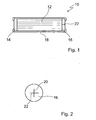
- FIG. 1 an inventively executed core assembly of a pencil ignition coil; and FIG. 2 a top view of a buffer of the Fig. 1 illustrated core assembly.
- FIG. 1 and 2 is a core assembly 10 of a pencil ignition coil of an ignition system designed as a gasoline engine internal combustion engine of a motor vehicle.
- the pencil ignition coil is used to supply a spark plug, not shown here, with high-voltage pulses, so that by means of the spark plug, an air / fuel mixture contained in a combustion chamber of the internal combustion engine can be ignited.
- the pencil ignition coil includes, in addition to the core assembly 10, a secondary winding body enclosing the core assembly, on which is disposed a secondary winding connected to a high voltage terminal leading to the spark plug.
- the secondary winding is in turn surrounded by a primary coil body, on which a primary winding sits, which is connected via a low-voltage connection to a DC electrical system of the motor vehicle.
- the core assembly 10 comprises a core 12 formed from stamped iron sheets, which is rod-shaped and is delimited at one end by a cover disk 14 formed from a permanent magnet and at its other end by a buffer of an elastic material, for example a foamed silicone material. At its periphery, the core 12 is surrounded by a casing 18 formed from a shrink tube, which rests on the front side on the one hand on the cover plate 14 and on the other hand on the buffer 16. The sheath of the core 12 formed from the sheath 18, the cover plate 14 and the buffer 16 can thus absorb temperature-induced changes in length of the core 12.
- the buffer 16 has two intersecting slots 20 and 22, which serve to vent the core assembly 10 during the evacuation of the vacuum chamber during the casting of the pencil ignition coil with an epoxy resin in a vacuum chamber and thus a rapid pressure equalization between the interior of the core assembly 10 and their environment.
- a core assembly of a pencil ignition coil may also be formed such that the cover disk is formed of a nonmagnetic material, for example of a hard silicone material, and a magnet is disposed between the buffer and the core. It is also conceivable to form the core assembly with two permanent magnets, one of which is formed by the cover and the other is arranged between the core and the buffer.
Landscapes
- Engineering & Computer Science (AREA)
- Power Engineering (AREA)
- Ignition Installations For Internal Combustion Engines (AREA)
Description
- Die Erfmdung geht von einer Stabzündspule einer Zündanlage einer Brennkraftmaschine, insbesondere einer Brennkraftmaschine eines Kraftfahrzeuges, gemäß der im Oberbegriff des Patentanspruches 1 näher definierten Art aus.
- Eine derartige Stabzündspule ist aus der Praxis bekannt und dient insbesondere zur Ansteuerung einer Zündkerze einer nach dem Otto-Prinzip arbeitenden Kraftfahrzeugbrennkraftmaschine. Die Stabzündspule bildet dabei einen Energiespeicher und Transformator, mittels dessen elektrische Energie einer vergleichsweise niedrigen Versorgungsspannung, die in der Regel durch ein Gleichspannungsbordnetz des betreffenden Kraftfahrzeuges bereitgestellt wird, in magnetische Energie umgewandelt wird, welche zu einem gewünschten Zeitpunkt, zu dem ein Zündimpuls an die zu einer Zündung eines Kraftstoffgemisches im Brennraum der Brennkraftmaschine dienenden Zündkerze abgegeben werden soll, in einen Hochspannungsimpuls umgesetzt wird.
- Die bekannte Stabzündspule umfasst eine auf einem Primärspulenkörper angeordnete Primärwicklung, die mit einem Niederspannungsanschluss verbunden ist, und eine konzentrisch zu der Primärwicklung angeordnete, auf einen Sekundärspulenkörper gewickelte Sekundärwicklung, die mit einem Hochspannungsanschluss verbunden ist, der zur Verbindung mit der Zündkerze dient. Die Spulenkörper umschließen eine Kernbaugruppe der Stabzündspule, die ein stabförmiges Paket aus ferromagnetischen Blechen, eine an einer Stirnseite des Lamellenpakets angeordnete Abdeckung, einen an der anderen Stirnseite des Lamellenpakets angeordneten Puffer und eine Umhüllung aus Kunststoff umfasst. Die Abdeckung, der Puffer und die Umhüllung der Kernbaugruppe dienen dazu, ein ausgehärtetes Vergussmaterial, das Hohlräume der Stabzündspule mit einem Vergussmaterial ausFüllt, vor den scharfkantigen Blechen des Lamellenpakets zu schützen und damit das Risiko einer Ausbildung von Rissen in dem Vergussmaterial zu mindern.
- Bei der Montage der Zündspule wird die Kernbaugruppe während einer Vormontage in einem Gehäuse der Zündspule angeordnet. Anschließend wird die vormontierte Zündspule in einer Vergusskammer nach einem so genannten VakuumvergussVerfahren mit einem aus Epoxidharz gebildeten Gießharz vergossen. Das Vergießen erfolgt im Vakuum, um alle Hohlräume der Zündspule mit dem Epoxidharz bzw. Gießharz zu befüllen und die Wicklungen imprägnieren zu können. Da das Blechpaket der Kernbaugruppe von der Kunststoffumhüllung, dem Puffer und der Abdeckung umschlossen ist, entsteht bei der Evakuierung der Gießkammer ein Druckgefälle zwischen dem Inneren der Kernbaugruppe und deren Umgebung. Das Druckgefälle wird aber nur sehr langsam abgebaut, so dass auch während des unter Vakuum erfolgenden Vergusses der Zündspule Luft aus der Kernbaugruppe austritt, was zu einer Blasenbildung in dem ausgehärteten Gießharz oder auch an der Oberfläche des ausgehärteten Gießharzes führen kann. Die Blasenbildung kann die Funktion der Stabzündspule über deren Lebensdauer beeinträchtigen.
- Die
Patentschrift DE 199 27 820 C1 zeigt eine Stabzündspule, bei der axial beiderseits eines weichmagnetischen Kerns Gummipuffer angeordnet sind. Einer der beiden Gummipuffer weist eine zentrale Bohrung auf. - Der Erfindung liegt die Aufgabe zugrunde, eine Stabzündspule der einleitend genannten Art zu schaffen, bei der sich beim Verguss mit einem Gießharz in einem Vakuum kein wesentliches Druckgefälle zwischen dem Inneren der Kernbaugruppe und deren Umgebung ausbilden kann.
- Die erfindungsgemäße Stabzündspule einer Zündanlage einer Brennkraftmaschine, insbesondere einer Brennkraftmaschine eines Kraftfahrzeuges, mit den Merkmalen nach dem Oberbegriff des Patentanspruches 1 und zumindest einem Luftdurchlass, der aus mindestens einem Schlitz gebildet ist, mit dem der Puffer ausgebildet ist, hat den Vorteil, dass sich beim Evakuieren einer zur Herstellung eines Gießharzvergusses der Stabzündspule dienenden Vergusskammer kein Druckgefälle zwischen dem Inneren der Kernbaugruppe und deren Umgebung aufbauen kann, da über den Luftdurchlass ein schneller Druckausgleich möglich ist. Etwaig in der Kernbaugruppe vorhandene Luft kann also beim Evakuieren der Vergusskammer über den Luftdurchlass des aus einem elastischen Material gebildeten Puffers entweichen. Bei einer erfindungsgemäß ausgebildeten Stabzündspule ist damit gewährleistet, dass das in der Regel aus Epoxidharz gebildete Vergussmaterial der Zündspule im ausgehärteten Zustand keine Blasen aufweist, die durch einen Luftaustritt aus der Kernbaugruppe resultieren.
- Über den Schlitz kann die Kernbaugruppe entlüftet werden. Jedoch kann über den Schlitz kein Gießharz in die Kernbaugruppe eindringen, da dieses in der Regel eine so hohe Viskosität aufweist, dass es nicht durch einen aus einem Schnitt gebildeten Schlitz eines elastischen Materials treten kann. Damit ist auch ausgeschlossen, dass durch das aus dem Gießharz gebildete Vergussmaterial die Funktion des Puffers, der eine Längenänderung des Blechpakets bei einer Temperaturänderung ausgleicht, eingeschränkt wird.
- Bei einer besonders wirksamen Ausführungsform der Stabzündspule nach der Erfmdung durchgreifen mindestens zwei sich kreuzende Schlitze den Puffer. Die so durch die Schlitze gebildeten Laschen des Puffers arbeiten dann nach Art von Entlüftungsklappen.
- Weitere Vorteile und vorteilhafte Ausgestaltungen des Gegenstandes nach der Erfmdung sind der Beschreibung, der Zeichnung und den Patentansprüchen entnehmbar.
- Ein Ausführungsbeispiel einer Stabzündspule nach der Erfindung ist in der Zeichnung schematisch vereinfacht dargestellt und wird in der nachfolgenden Beschreibung näher erläutert.
-
Figur 1 eine erfindungsgemäß ausgeführte Kernbaugruppe einer Stabzündspule; undFigur 2 eine Aufsicht auf einen Puffer der inFig. 1 dargestellten Kernbaugruppe. - In den
Figuren 1 und 2 ist eine Kernbaugruppe 10 einer Stabzündspule einer Zündanlage einer als Otto-Motor ausgelegten Brennkraftmaschine eines Kraftfahrzeuges dargestellt. Die Stabzündspule dient zur Versorgung einer hier nicht näher dargestellten Zündkerze mit Hochspannungsimpulsen, so dass mittels der Zündkerze ein in einem Brennraum der Brennkraftmaschine enthaltenes Luft/Kraftstoff-Gemisch entzündet werden kann. - Die Stabzündspule umfasst im zusammengebauten Zustand neben der Kernbaugruppe 10 einen die Kernbaugruppe umschließenden Sekundärwickelkörper, auf dem eine Sekundärwicklung angeordnet ist, die mit einem Hochspannungsanschluss verbunden ist, der zu der Zündkerze führt. Die Sekundärwicklung ist wiederum von einem Primärspulenkörper umgeben, auf dem eine Primärwicklung sitzt, die über einen Niederspannungsanschluss mit einem Gleichspannungsbordnetz des Kraftfahrzeuges verbunden ist.
- Die Kernbaugruppe 10 umfasst einen aus gestanzten Eisenblechen gebildeten Kern 12, der stabförmig ausgebildet ist und an einer Stirnseite von einer aus einem Permanentmagneten gebildeten Abdeckscheibe 14 und an seiner anderen Stirnseite von einem Puffer aus einem elastischen Material, beispielsweise aus einem geschäumten Silikonwerkstoff, begrenzt ist. An seinem Umfang ist der Kern 12 von einer aus einem Schrumpfschlauch gebildeten Umhüllung 18 umgeben, die stirnseitig einerseits auf der Abdeckscheibe 14 und andererseits auf dem Puffer 16 aufliegt. Die aus der Umhüllung 18, der Abdeckscheibe 14 und dem Puffer 16 gebildete Ummantelung des Kerns 12 kann damit temperaturbedingte Längenänderungen des Kerns 12 aufnehmen.
- Wie
Fig. 2 zu entnehmen ist, weist der Puffer 16 zwei sich kreuzende Schlitze 20 und 22 auf, die beim Vergießen der Stabzündspule mit einem Epoxidharz in einer Vakuumkammer während des Evakuierens der Vakuumkammer zum Entlüften der Kernbaugruppe 10 dienen und somit einen schnellen Druckausgleich zwischen dem Inneren der Kernbaugruppe 10 und deren Umgebung ermöglichen. - Alternativ kann eine Kernbaugruppe einer Stabzündspule auch so ausgebildet sein, dass die Abdeckscheibe aus einem nichtmagnetischen Material, beispielsweise aus einem harten Silikonwerkstoff, gebildet ist und ein Magnet zwischen dem Puffer und dem Kern angeordnet ist. Auch ist es denkbar, die Kernbaugruppe mit zwei Permanentmagneten auszubilden, von denen einer von der Abdeckscheibe gebildet ist und der andere zwischen dem Kern und dem Puffer angeordnet ist.
Claims (2)
- Stabzündspule einer Zündanlage einer Brennkraftmaschine, insbesondere einer Kraftfahrzeugbrennkraftmaschine, umfassend eine auf einem Primärspulenkörper angeordnete Primärwicklung, eine auf einem Sekundärspulenkörper angeordnete Sekundärwicklung sowie eine Kernbaugruppe (10), die ein stabförmiges Blechpaket (12) aus einem ferromagnetischen Material, eine an einer Stirnseite des Blechpakets (12) angeordnete Abdeckung (14), einen aus einem elastischen Material gebildeten, an der zweiten Stirnseite des Blechpakets (12) angeordneten Puffer (16) mit einem Luftdurchlass (20,22) und eine Umhüllung (18) aus Kunststoff umfasst, dadurch gekennzeichnet, dass der Luftdurchlass (20, 22) aus zumindest einem Schlitz gebildet ist.
- Stabzündspule nach Anspruch 1, dadurch gekennzeichnet, dass mindestens zwei sich kreuzende Schlitze (20, 22) den Puffer (16) durchgreifen.
Applications Claiming Priority (2)
| Application Number | Priority Date | Filing Date | Title |
|---|---|---|---|
| DE200410008986 DE102004008986A1 (de) | 2004-02-23 | 2004-02-23 | Stabzündspule |
| DE102004008986 | 2004-02-23 |
Publications (3)
| Publication Number | Publication Date |
|---|---|
| EP1566819A2 EP1566819A2 (de) | 2005-08-24 |
| EP1566819A3 EP1566819A3 (de) | 2007-10-03 |
| EP1566819B1 true EP1566819B1 (de) | 2011-05-18 |
Family
ID=34706905
Family Applications (1)
| Application Number | Title | Priority Date | Filing Date |
|---|---|---|---|
| EP20040106487 Ceased EP1566819B1 (de) | 2004-02-23 | 2004-12-10 | Stabzündspule |
Country Status (2)
| Country | Link |
|---|---|
| EP (1) | EP1566819B1 (de) |
| DE (1) | DE102004008986A1 (de) |
Families Citing this family (2)
| Publication number | Priority date | Publication date | Assignee | Title |
|---|---|---|---|---|
| DE102005039761B4 (de) * | 2005-08-23 | 2014-04-03 | Robert Bosch Gmbh | Kernbaugruppe, insbesondere für eine Zündspule einer Brennkraftmaschine |
| DE102008000827A1 (de) * | 2008-03-26 | 2009-10-01 | Robert Bosch Gmbh | Zündspule |
Family Cites Families (3)
| Publication number | Priority date | Publication date | Assignee | Title |
|---|---|---|---|---|
| JP3604917B2 (ja) * | 1998-09-07 | 2004-12-22 | 株式会社日立製作所 | 内燃機関用点火コイル |
| DE19927820C1 (de) * | 1998-10-27 | 2000-07-06 | Bremi Auto Elektrik Ernst Brem | Stabzündspule |
| JP4062951B2 (ja) * | 2001-05-08 | 2008-03-19 | 株式会社デンソー | 内燃機関用点火コイル |
-
2004
- 2004-02-23 DE DE200410008986 patent/DE102004008986A1/de not_active Withdrawn
- 2004-12-10 EP EP20040106487 patent/EP1566819B1/de not_active Ceased
Also Published As
| Publication number | Publication date |
|---|---|
| EP1566819A2 (de) | 2005-08-24 |
| EP1566819A3 (de) | 2007-10-03 |
| DE102004008986A1 (de) | 2005-09-08 |
Similar Documents
| Publication | Publication Date | Title |
|---|---|---|
| DE19957172A1 (de) | Brennstoffeinspritzventil | |
| DE102009002407A1 (de) | Zündspule für eine Brennkraftmaschine und Verfahren zu deren Herstellung | |
| DE102013211816A1 (de) | Elektromagnetische Schaltvorrichtung | |
| DE10055589A1 (de) | Zündspule mit außerhalb der Sekundärwicklung angeordneter Primärwicklung | |
| DE10108652C2 (de) | Zündspule mit mikroeingekapselten Magneten | |
| DE19537301C2 (de) | Zündspulenvorrichtung für einen Verbrennungsmotor und Verfahren zu deren Herstellung | |
| EP1566819A2 (de) | Stabzündspule | |
| DE19623399A1 (de) | Zündung für Brennkraftmaschinen | |
| DE102013208058A1 (de) | Magnetisch vorgespannte Drossel | |
| EP1694960B1 (de) | Zündspule | |
| WO1986001878A1 (fr) | Bougie-crayon de chauffage pour moteurs a combustion interne | |
| DE102005039761B4 (de) | Kernbaugruppe, insbesondere für eine Zündspule einer Brennkraftmaschine | |
| DE10231510B3 (de) | Abdichtung einer Zündspule | |
| DE2822442B1 (de) | Dosierkolbenpumpe | |
| EP1913607B1 (de) | Lampensockel für eine hochdruckentladungslampe und hochdruckentladungs- lampe | |
| EP3576972B1 (de) | Einfüllstutzen für einen betriebsflüssigkeitsbehälter für ein kraftfahrzeug mit verbessertem fehlbetankungsschutz | |
| DE10360338A1 (de) | Zündspule für einen Ottomotor und Verfahren zu deren Herstellung | |
| EP1440498B1 (de) | Stabspule für zündanlagen | |
| DE3412003A1 (de) | Elektrische spule, insbesondere fuer die zuendanlage einer brennkraftmaschine bestimmte zuendspule | |
| DE102007060214A1 (de) | Zündspulenanordnung für eine Brennkraftmaschine und Verfahren zur Ansteuerung einer derartigen Zündspulenanordnung | |
| WO2008046711A1 (de) | Zündspule, insbesondere für eine brennkraftmaschine eines kraftfahrzeuges | |
| DE102006058351B3 (de) | Verfahren zur Herstellung eines Spulenkörpers, Verfahren zur Herstellung eines Solenoids, Solenoid und Einspritzsystem mit einem solchen Solenoid | |
| DE102006060627A1 (de) | Zündspule für eine Brennkraftmaschine | |
| DE10257101B3 (de) | Stabzündspule | |
| DE102007048461A1 (de) | Elektromagnetisches Ventil, und Verfahren zu dessen Herstellung |
Legal Events
| Date | Code | Title | Description |
|---|---|---|---|
| PUAI | Public reference made under article 153(3) epc to a published international application that has entered the european phase |
Free format text: ORIGINAL CODE: 0009012 |
|
| AK | Designated contracting states |
Kind code of ref document: A2 Designated state(s): AT BE BG CH CY CZ DE DK EE ES FI FR GB GR HU IE IS IT LI LT LU MC NL PL PT RO SE SI SK TR |
|
| AX | Request for extension of the european patent |
Extension state: AL BA HR LV MK YU |
|
| PUAL | Search report despatched |
Free format text: ORIGINAL CODE: 0009013 |
|
| AK | Designated contracting states |
Kind code of ref document: A3 Designated state(s): AT BE BG CH CY CZ DE DK EE ES FI FR GB GR HU IE IS IT LI LT LU MC NL PL PT RO SE SI SK TR |
|
| AX | Request for extension of the european patent |
Extension state: AL BA HR LV MK YU |
|
| 17P | Request for examination filed |
Effective date: 20080403 |
|
| AKX | Designation fees paid |
Designated state(s): DE FR IT |
|
| 17Q | First examination report despatched |
Effective date: 20090408 |
|
| GRAP | Despatch of communication of intention to grant a patent |
Free format text: ORIGINAL CODE: EPIDOSNIGR1 |
|
| GRAS | Grant fee paid |
Free format text: ORIGINAL CODE: EPIDOSNIGR3 |
|
| GRAA | (expected) grant |
Free format text: ORIGINAL CODE: 0009210 |
|
| AK | Designated contracting states |
Kind code of ref document: B1 Designated state(s): DE FR IT |
|
| REG | Reference to a national code |
Ref country code: DE Ref legal event code: R096 Ref document number: 502004012520 Country of ref document: DE Effective date: 20110630 |
|
| PLBE | No opposition filed within time limit |
Free format text: ORIGINAL CODE: 0009261 |
|
| STAA | Information on the status of an ep patent application or granted ep patent |
Free format text: STATUS: NO OPPOSITION FILED WITHIN TIME LIMIT |
|
| 26N | No opposition filed |
Effective date: 20120221 |
|
| REG | Reference to a national code |
Ref country code: DE Ref legal event code: R097 Ref document number: 502004012520 Country of ref document: DE Effective date: 20120221 |
|
| REG | Reference to a national code |
Ref country code: FR Ref legal event code: PLFP Year of fee payment: 12 |
|
| REG | Reference to a national code |
Ref country code: FR Ref legal event code: PLFP Year of fee payment: 13 |
|
| REG | Reference to a national code |
Ref country code: FR Ref legal event code: PLFP Year of fee payment: 14 |
|
| PGFP | Annual fee paid to national office [announced via postgrant information from national office to epo] |
Ref country code: FR Payment date: 20171219 Year of fee payment: 14 |
|
| PGFP | Annual fee paid to national office [announced via postgrant information from national office to epo] |
Ref country code: IT Payment date: 20171218 Year of fee payment: 14 |
|
| PGFP | Annual fee paid to national office [announced via postgrant information from national office to epo] |
Ref country code: DE Payment date: 20180223 Year of fee payment: 14 |
|
| REG | Reference to a national code |
Ref country code: DE Ref legal event code: R119 Ref document number: 502004012520 Country of ref document: DE |
|
| PG25 | Lapsed in a contracting state [announced via postgrant information from national office to epo] |
Ref country code: IT Free format text: LAPSE BECAUSE OF NON-PAYMENT OF DUE FEES Effective date: 20181210 Ref country code: FR Free format text: LAPSE BECAUSE OF NON-PAYMENT OF DUE FEES Effective date: 20181231 Ref country code: DE Free format text: LAPSE BECAUSE OF NON-PAYMENT OF DUE FEES Effective date: 20190702 |