EP1565619B1 - Dispositif pour amarrer un bateau a un batiment maritime - Google Patents
Dispositif pour amarrer un bateau a un batiment maritime Download PDFInfo
- Publication number
- EP1565619B1 EP1565619B1 EP03789101A EP03789101A EP1565619B1 EP 1565619 B1 EP1565619 B1 EP 1565619B1 EP 03789101 A EP03789101 A EP 03789101A EP 03789101 A EP03789101 A EP 03789101A EP 1565619 B1 EP1565619 B1 EP 1565619B1
- Authority
- EP
- European Patent Office
- Prior art keywords
- water
- based structure
- tower
- landing
- landing station
- Prior art date
- Legal status (The legal status is an assumption and is not a legal conclusion. Google has not performed a legal analysis and makes no representation as to the accuracy of the status listed.)
- Expired - Lifetime
Links
Images

Classifications
-
- E—FIXED CONSTRUCTIONS
- E02—HYDRAULIC ENGINEERING; FOUNDATIONS; SOIL SHIFTING
- E02B—HYDRAULIC ENGINEERING
- E02B17/00—Artificial islands mounted on piles or like supports, e.g. platforms on raisable legs or offshore constructions; Construction methods therefor
- E02B17/0034—Maintenance, repair or inspection of offshore constructions
-
- B—PERFORMING OPERATIONS; TRANSPORTING
- B66—HOISTING; LIFTING; HAULING
- B66C—CRANES; LOAD-ENGAGING ELEMENTS OR DEVICES FOR CRANES, CAPSTANS, WINCHES, OR TACKLES
- B66C13/00—Other constructional features or details
- B66C13/02—Devices for facilitating retrieval of floating objects, e.g. for recovering crafts from water
-
- B—PERFORMING OPERATIONS; TRANSPORTING
- B66—HOISTING; LIFTING; HAULING
- B66F—HOISTING, LIFTING, HAULING OR PUSHING, NOT OTHERWISE PROVIDED FOR, e.g. DEVICES WHICH APPLY A LIFTING OR PUSHING FORCE DIRECTLY TO THE SURFACE OF A LOAD
- B66F7/00—Lifting frames, e.g. for lifting vehicles; Platform lifts
- B66F7/02—Lifting frames, e.g. for lifting vehicles; Platform lifts with platforms suspended from ropes, cables, or chains or screws and movable along pillars
-
- E—FIXED CONSTRUCTIONS
- E02—HYDRAULIC ENGINEERING; FOUNDATIONS; SOIL SHIFTING
- E02B—HYDRAULIC ENGINEERING
- E02B3/00—Engineering works in connection with control or use of streams, rivers, coasts, or other marine sites; Sealings or joints for engineering works in general
- E02B3/04—Structures or apparatus for, or methods of, protecting banks, coasts, or harbours
- E02B3/06—Moles; Piers; Quays; Quay walls; Groynes; Breakwaters ; Wave dissipating walls; Quay equipment
- E02B3/068—Landing stages for vessels
-
- E—FIXED CONSTRUCTIONS
- E02—HYDRAULIC ENGINEERING; FOUNDATIONS; SOIL SHIFTING
- E02B—HYDRAULIC ENGINEERING
- E02B17/00—Artificial islands mounted on piles or like supports, e.g. platforms on raisable legs or offshore constructions; Construction methods therefor
- E02B2017/0091—Offshore structures for wind turbines
Definitions
- the invention relates to a hydraulic structure with a tower-shaped section and a device for applying at least one watercraft to the tower-shaped section of a hydraulic structure, wherein the device has a platform-like docking station and the hydraulic structure is arranged a lifting device for moving the docking station, so that the docking station between a first position in the area of the water surface for the application of a watercraft and a second position above the water surface, in which the application of a watercraft is not possible, along the wall of the tower-shaped portion of the hydraulic structure movable and further at least in its first position about an axis of rotation which is approximately in Direction of movement of the docking station between the first and the second position extends, at least in a limited angular range along the wall of the tower-shaped portion of the hydraulic structure is freely pivotable.
- Mooring devices for tower-shaped hydraulic structures are already known. Usually, these are in the water surface, so that a person of z. B. can exceed a ship and then via a ladder that leads up to the tower-shaped hydraulic structure, a service platform or wind turbines and the nacelle reached. In the event that the applicator can not be reached for some reason, e.g. B. in too high waves, in addition, a platform can be additionally provided at an elevated point on the hydraulic structure, where people can be lowered from a helicopter by means of a winch. The use of helicopters for this purpose is very expensive, in addition, the lowering over a winch is dangerous.
- the US 4,590,634 A describes a common gangway or swing bridge for docking a ship on an offshore platform.
- the outer end of the swing bridge is secured to a rope of a crane.
- the inner end of the pivoting bridge is articulated on the offshore platform, by means of a pivot bearing arrangement, which allows both a pivoting in the vertical direction about a horizontally arranged hinge pin and a rotational movement in the horizontal direction about a vertically arranged pivot pin.
- the pivot bearing assembly is disposed at a fixed height on the offshore platform and fixes the inner end of the pivot bridge in height with respect to the offshore platform.
- the US 4,740,108 A shows a lifting bridge, which is suspended at their ends by means of cables to vertical supports and also on the supports enclosing tubular guides with the supports is in sliding engagement, whereby the lifting bridge is raised and lowered.
- a similar lift bridge is in the AU 425219 B disclosed, which differs from the previously described known lifting bridge in that instead of a cable suspension the lifting movement is effected by a hydraulic.
- the US 5,868,514 A describes a watercraft lift to selectively lift a small craft such as a jet ski out of the water and let it into the water.
- a platform is supported on a vertical pole and by means of a cable pulling device in the vertical direction along the pile between a lower position in which the platform is immersed in the water, and an upper position in which the platform above the water surface is located at the height of an adjacent bridge, can be raised and lowered.
- a hydraulic structure with a tower-shaped section and a device for applying at least one watercraft to the tower-shaped section of a hydraulic structure wherein the device has a platform-like docking station and a lifting device for moving the landing station is arranged on the hydraulic structure, so that the docking station between a first Position in the area of the water surface to create a vessel and one above the Water surface located second position in which the application of a watercraft is not possible, along the wall of the tower-shaped portion of the hydraulic structure movable and further at least in its first position about an axis of rotation which is approximately in the direction of movement of the landing station between the first and the second position runs, at least in a limited angular range along the wall of the tower-shaped portion of the hydraulic structure is freely pivotable, characterized in that the platform-like docking station surrounds the tower-shaped portion of the hydraulic structure, wherein the tower-shaped portion has a circular cross section and / or on the wall approximately in the direction of movement the landing station extending sliding elements are designed
- a landing device at the tower-shaped section of a hydraulic structure, a landing device can be realized, the landing station of which is protected by methods in the second position from the sea state.
- the application device is not exposed to permanent waves and salt water, whereby the material is spared and thus the lifetime of such a docking device can be considerably extended.
- a safe driving of the hydraulic structure and thus a safe transfer of a person from a ship to the hydraulic structure allows by the mooring station depending on water level and wave height to the first position or an overlying position accordingly can be adjusted.
- the docking station is therefore not articulated directly to the hydraulic structure via a joint, hinge or the like.
- the docking station relative to the corresponding wall of the tower-shaped portion of the hydraulic structure, at least in the horizontal direction freely movable.
- the free Verschenkbarkeit is realized only by the arrangement of the lifting device.
- the inventive suspension of the landing station, the surface roughness of the wall of the hydraulic structure is not affected in an undesirable manner, since neither the docking station nor the lifting device and other components are in the diving area.
- Another - and particularly important - advantage of the special arrangement of the landing station according to the present invention is that a resilient mounting of the landing station is provided in the horizontal direction, whereby at least a portion of the energy occurring in at Converted rotational energy and thus the hydraulic structure is not burdened by additional torsional moments.
- the docking station is arranged on the lifting device such that the landing station is freely strigkbar at least in a limited angular range along the wall of the tower-shaped portion of the hydraulic structure about a pivot or rotation axis, approximately in by the lifting movement between The first and second position defined direction of movement of the landing station runs without even forming a hinge or a joint. Because according to the teaching of the invention there is no direct pivotal connection between the landing station and the hydraulic structure. Rather, the free pivoting is realized only by the arrangement of the lifting device.
- the second position forms in particular a rest position in which the docking station is when it is not needed, but is out of order.
- the docking station hangs on the lifting device.
- the lifting device on a cable on which hangs the docking station.
- the lifting device usually has a deflection device to be provided on the hydraulic structure, which preferably has at least one Has deflection pulley, for deflecting the cable and a below the deflection within the hydraulic structure to be arranged drive means for winding and unwinding of the cable, wherein it is particularly advantageous for structural and static considerations, the drive means for placement in the bottom area, ie in the foot or on the Foundation to provide the hydraulic structure.
- the application device is in sliding engagement with a wall of the hydraulic structure and is supported on the wall, preferably by means of a sliding and / or roller bearing.
- the sliding elements may extend approximately in the direction of movement of the docking station.
- the sliding elements can expediently be rail-shaped.
- the sliding elements may be designed and arranged such that their sliding surfaces, with which the application station is in sliding engagement, are arranged substantially equidistant from one another over their entire length in the direction of movement of the application station.
- the sliding elements can serve as spacers to compensate for the change in the shape of the hydraulic structure accordingly; This is especially true in the case of a conical shape of the hydraulic structure to compensate for the smaller diameter accordingly.
- the landing station has a truss structure.
- the impact forces introduced punctually by a mooring ship are picked up and distributed by a truss structure. Since the impact forces at the individual nodes of the trusses divide and thereby act distributed at several points on the hydraulic structure, the individual loads for the hydraulic structure are substantially lower than at punctual impact.
- a truss structure has a spring effect. Because due to the elasticity of the truss structure formed by the truss structure and thereby relatively long deformation path, the hydraulic structure is also spared in the event of a shock. Finally, a truss structure has a relatively low weight and offers less attack surface in Seeschlag as a continuous plating.
- the truss structure has at least one rod which extends past the wall of the hydraulic structure, preferably tangentially to the latter.
- the at least one rod should extend approximately from the landing.
- Such an arrangement of bars is particularly advantageous for absorbing impact forces in order to derive them in a particularly gentle manner for the hydraulic structure.
- FIG. 1 the lower part of a tower 2 is shown, which is anchored on a foundation 4 on the seabed 6.
- the tower 2 may be, for example, the tower of an offshore wind power station.
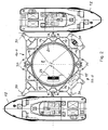
- a platform 10 is provided, which surrounds the tower 2 in the illustrated embodiment, in particular FIG. 2 lets recognize.
- the platform 10 may have different basic shapes. For example, it is conceivable to make the platform 10 circular or polygonal.
- FIG. 2 With regard to the basic form, two different embodiments are shown in each case in half, the according to FIG. 2 upper half represents a platform of rectangular basic shape and is denoted by the reference numeral "10-1" and the according to FIG.
- FIG. 1 is the platform 10 between a lower first position, the in FIG. 1 is denoted by “I”, and an upper second position which is in FIG. 1 is denoted by "II", mounted in the vertical direction along the tower 2 movable, with the aid of a lifting device described in more detail below.
- the lower first position I is the landing position in which at least one ship can dock on platform 10; in the figures, two ships 12 are shown by way of example, have moored diametrically opposite to the platform.
- the platform 10 has, in the illustrated embodiment, a welded pipe construction, which forms a framework, to suitcase occurring ramming abkoffern by mooring ships against the tower 2.
- FIG. 2 identifiable pairs of rods 14, 15, each of which is a rod 14 from a location adjacent to the center of the outside of the platform 10 tangent to one side of the wall 2a of the tower 2 and the other rod 15 from one adjacent to the center of the Outside of the platform 10 opposite location extends tangentially to the other side of the wall 2a of the tower 2, as FIG. 2 lets recognize.
- the platform 10 spans the tower 2 in several planes, which are designed in truss structure.
- the individual levels are interconnected by unspecified vertical pipe supports.
- additional pipe supports are additionally drawn diagonally from level to level.
- the top of the platform 10 is provided with unspecified carrier grates to make the platform 10 accessible. As a fall protection, the platform 10 is carried out to the sea side with a railing 16.
- each quadrant of the tower 2 is provided in the illustrated embodiment with two slide rails 18.
- the slide rails 18 form on its outer side sliding surfaces, wherein the slide rails 18 are arranged in the illustrated embodiment on the tower 2, that the sliding surfaces lie in a cylindrical plane to corresponding in an upper conical portion 2b of the tower 2 over the height of decreasing diameter compensate.
- each level of the platform 10 by a circumferential support ring 20 (see. FIG. 2 ) completed.
- This support ring is recessed only in the area of an emergency ladder, not shown on the tower 2 and serves as an abutment against the slide rails 18. Accordingly, the inner surface of the support rings 20 abuts against the slide rails 18 and thus is in sliding engagement with these.
- the carrier rings 20 are covered on their inner surfaces with appropriate suitable sliding material.
- the platform 10 is suspended in the illustrated embodiment on four tension cables 22, each via pulleys 24 in the interior of the tower. 2 be redirected.
- the pulleys 24 are arranged in the wall 2a of the tower 2 above the upper position II.
- non-illustrated inlet openings are formed there, through which the ropes 22 enter the interior of the tower 2.
- a traction cable 22 and an associated deflection roller 24 are provided on the tower 2 in each quadrant.
- the tower sleeve bushings are arranged for the four traction cables 22.
- the traction cables 22 are deflected to a drum winch 26, which is placed inside the tower 2, as in FIG. 2 is indicated.
- the winch 26 sits in the foot of the tower 2 above the foundation 4.
- the winch 26 is driven by a first electric motor, not shown.
- a second electric motor also not shown, is also provided in order to be able to drive the winch in the event of a fault in the first electric motor.
- the winch 26 should be designed so that in the event of power failure, the winch 26 can also be operated mechanically, eg by means of a hand crank.
- the winch 26 is further provided with a brake, not shown, in order to fix the platform 10 at any desired height between the lower position I and the upper position II.
- limit switches may be provided in the winch 26 to turn off the winch 26 when the platform 10 reaches one of the two positions I or II.
- the platform 10 is freely pivotable about the vertical longitudinal axis of the tower 2 over a limited angular range on both sides. Therefore, the traction cables 22 are rotatably mounted on the platform 10, so that even when pivoting the platform 10, caused by the application of a ship 12, the traction cables 22 do not rotate. For this purpose, as tension cables 22 also low-twist ropes are used.
- the winch 26 can be operated by means of a remote control from the ship 12 or from the platform 10. Furthermore, a third operating option can be provided on the tower 2.
- the tower 2 can also be arranged in the region of the lower position I stops not shown, on which the platform 10 comes to lie in its lower position I.
- the platform 10 In the upper position II, the platform 10 can be mechanically locked, by a locking device, not shown, whereby the traction cables 22 and the winch 26 are relieved.
- the platform 10 is equipped with a plurality of fenders 30 of different sizes.
- larger fenders are provided in the illustrated embodiments at the corners of the platform 10-1 and 10-2 than at intermediate points.
- the individual fenders 30 are cylindrical and rotatably mounted about vertical axes of rotation, so that when creating a ship 10, a part of the energy occurring by impact forces is converted into rotational energy and thus the tower 2 is not additionally burdened by torsional.
- the so-suggesting ship 12 turns off when driving in the right direction and minimizes the friction occurring during forward and backward movement of the ship 12.
- the fenders consist of a body of cell-closed plastic material whose hardness increases from outside to inside.
- the degree of hardness of Fenders 30 should be relatively soft, i. with a low Shore hardness, be designed to achieve the highest possible degree of compressibility. In this way, as much energy of the elastic shock should be absorbed in the fenders 30 in order to keep the load in the platform 10 and the tower 2 as low as possible.
- a vertical transfer ladder 32 (see. FIG. 1 ), which extends from the lower to the upper level of the platform 10 and is bounded laterally by vertical protective strips, not shown. Such a ladder 32 is intended to prevent trapping of persons when crossing the ship 12 to the platform 10.
- the carrier rings 20 are recessed in the region of an emergency conductor arranged on the tower 2, which is not shown in the figures.
- a ship picks up 12 service personnel at the port or from a larger work ship and relocates it to the job site.
- the platform 10 is moved from the upper position II, which usually forms the rest or stowed position, adjusted to one of the tides and the sea level adjusted height down.
- the skipper then maneuvers the vessel 12 from the optimal direction to the platform 10.
- the service personnel adjust a swell and climb the wave mountain on the ladder 32 on the platform 10 or directly on the platform 10, as in FIG. 1 is shown schematically.
- the platform 10 can of course be adjusted in height accordingly, the second position II forms the upper position.
- the tower 2 has an entrance door in the region of the upper position II in order to carry out further maintenance work there and also to be able to reach the interior of the tower 2.
- the platform 10 is in any case moved back to the upper position II, which, as already mentioned, also forms the rest or stowed position.
- the upper position II is located so far above the water surface, that the platform 10 of swell and Seeschlag can not be achieved.
Landscapes
- Engineering & Computer Science (AREA)
- General Engineering & Computer Science (AREA)
- Mechanical Engineering (AREA)
- Structural Engineering (AREA)
- Civil Engineering (AREA)
- Ocean & Marine Engineering (AREA)
- Geology (AREA)
- Environmental & Geological Engineering (AREA)
- Life Sciences & Earth Sciences (AREA)
- Prevention Of Electric Corrosion (AREA)
- Other Liquid Machine Or Engine Such As Wave Power Use (AREA)
- Jib Cranes (AREA)
- Control Of Metal Rolling (AREA)
- Devices For Checking Fares Or Tickets At Control Points (AREA)
- Wind Motors (AREA)
- Ship Loading And Unloading (AREA)
- Harvesting Machines For Specific Crops (AREA)
Claims (12)
- Bâtiment maritime avec une partie en forme de tour et un dispositif d'amarrage d'au moins un bateau (12) sur la partie en forme de tour du bâtiment maritime (2), le dispositif présentant un poste d'amarrage (10) en forme de plateforme et sur le bâtiment maritime (2) étant disposé un dispositif de levage (22, 24, 26) pour déplacer le poste d'amarrage (10), de sorte que le poste d'amarrage (10) puisse être déplacé entre une première position (I) dans la zone de la surface de l'eau pour amarrer un bateau (13) et une seconde position (II) se trouvant au-dessus de la surface de l'eau, dans laquelle l'amarrage d'un bateau (12) n'est pas possible, le long de la paroi de la partie en forme de tour du bâtiment maritime (2) et de plus puisse pivoter librement au moins dans une première position (I) autour d'un axe de rotation qui s'étend à peu près dans le sens du mouvement du poste d'amarrage (10) entre la première et la seconde position (I, II), au moins dans une zone angulaire limitée le long de la paroi de la partie en forme de tour du bâtiment maritime,
caractérisé en ce que le poste d'amarrage en forme de plateforme entoure la partie en forme de tour du bâtiment maritime, la partie en forme de tour présentant une section circulaire et/ou sur sa paroi (2a) étant réalisés et disposés des éléments glissants (18) s'étendant à peu près dans le sens de mouvement du poste d'amarrage (10) de telle sorte que leurs surfaces de glissement, avec lesquelles le poste d'amarrage (10) se trouve en prise de glissement, se trouvent dans un plan cylindrique et soient alignées de manière tangentielle à celui-ci. - Bâtiment maritime selon la revendication 1,
caractérisé en ce que la seconde position (II) forme une position de repos, dans laquelle le poste d'amarrage (10) est déplacé, lorsque celui-ci se trouve hors service. - Bâtiment maritime selon la revendication 1 ou 2,
caractérisé en ce que le poste d'amarrage (10) est accroché au dispositif de levage (22, 24, 26). - Bâtiment maritime selon la revendication 3,
caractérisé en ce que le dispositif de levage présente un câble Bowden (22), auquel est accroché le poste d'amarrage (10). - Bâtiment maritime selon la revendication 4,
caractérisé en ce que le dispositif de levage présente un dispositif de renvoi (24) disposé sur le bâtiment maritime (2), qui présente de préférence au moins une poulie de renvoi afin de renvoyer le câble Bowden (22) et un dispositif d'entraînement (26) disposé au-dessous du dispositif de renvoi (24) à l'intérieur du bâtiment maritime (2) pour enrouler et dérouler le câble Bowden (22). - Bâtiment maritime selon la revendication 5,
caractérisé en ce que le dispositif d'entraînement (26) est disposé dans la zone de fond du bâtiment maritime (2). - Bâtiment maritime selon au moins l'une quelconque des revendications précédentes,
caractérisé en ce qu'au cas où la partie en forme de tour présente une section circulaire, le poste d'amarrage (10) s'appuie au moyen d'un palier lisse et/ou d'un roulement à rouleaux contre la paroi (2a) du bâtiment maritime (2). - Bâtiment maritime selon au moins l'une quelconque des revendications précédentes,
caractérisé en ce que les éléments glissants (18) sont réalisés en forme de rail. - Bâtiment maritime selon au moins l'une quelconque des revendications précédentes,
caractérisé en ce que le poste d'amarrage (16) présente une construction en tréillis. - Bâtiment maritime selon la revendication 9,
caractérisé en ce que la construction en treillis présente au moins une barre (14, 15) qui s'étend devant la paroi (2a) du bâtiment maritime (2), de préférence de manière tangentielle à celui-ci. - Bâtiment maritime selon la revendication 10,
pour lequel le poste d'amarrage (10) présente au moins une zone d'amarrage, caractérisé en ce qu'au moins une barre (14, 15) s'étend à peu près depuis la zone d'amarrage. - Bâtiment maritime selon la revendication 11,
caractérisé par au moins une paire de barres (14, 15), dont l'une (14) s'étend depuis la zone d'amarrage vers un côté de la paroi (2a) et l'autre (15) depuis la zone d'amarrage vers l'autre côté de la paroi (2a) du bâtiment maritime (2).
Applications Claiming Priority (3)
| Application Number | Priority Date | Filing Date | Title |
|---|---|---|---|
| DE20218481 | 2002-11-29 | ||
| DE20218481U | 2002-11-29 | ||
| PCT/EP2003/013404 WO2004051002A2 (fr) | 2002-11-29 | 2003-11-28 | Dispositif pour amarrer un bateau à un bâtiment maritime |
Publications (2)
| Publication Number | Publication Date |
|---|---|
| EP1565619A2 EP1565619A2 (fr) | 2005-08-24 |
| EP1565619B1 true EP1565619B1 (fr) | 2008-07-30 |
Family
ID=32404480
Family Applications (1)
| Application Number | Title | Priority Date | Filing Date |
|---|---|---|---|
| EP03789101A Expired - Lifetime EP1565619B1 (fr) | 2002-11-29 | 2003-11-28 | Dispositif pour amarrer un bateau a un batiment maritime |
Country Status (6)
| Country | Link |
|---|---|
| EP (1) | EP1565619B1 (fr) |
| AT (1) | ATE403040T1 (fr) |
| AU (1) | AU2003293740A1 (fr) |
| DE (1) | DE50310262D1 (fr) |
| DK (1) | DK1565619T3 (fr) |
| WO (1) | WO2004051002A2 (fr) |
Families Citing this family (5)
| Publication number | Priority date | Publication date | Assignee | Title |
|---|---|---|---|---|
| DE102004049733B4 (de) * | 2004-10-08 | 2006-09-21 | Universität Rostock | Verfahren zur Minimierung des Einflusses von Sportbootanlegestellen und Sportbootübergängen an sandigen Außenküsten auf die Küstendynamik und die Umwelt, insbesondere auf die Lee-Erosion der Küste |
| AT506625B1 (de) | 2008-09-04 | 2009-10-15 | Palfinger Systems Gmbh | Instandhaltungsplattform |
| DE102008048609A1 (de) * | 2008-09-23 | 2010-04-08 | Stefan Leske | Anordnung zum sichern Übersetzen von Personal für Offshore-Windenergieanlagen |
| DE102012007699A1 (de) * | 2012-04-19 | 2013-10-24 | WeserWind GmbH Offshore Construction Georgsmarienhütte | Offshore-Bauwerk und Verfahren zum Übergang von einem Schiff zu einem Offshore-Bauwerk |
| CN108639256B (zh) * | 2018-05-30 | 2024-07-12 | 西伯瀚(上海)海洋装备科技有限公司 | 一种海洋平台登艇装置及海洋平台 |
Family Cites Families (6)
| Publication number | Priority date | Publication date | Assignee | Title |
|---|---|---|---|---|
| AU425219B2 (en) * | 1971-08-04 | 1972-06-19 | The Fish Board | Wharf structure |
| US4003473A (en) * | 1974-08-30 | 1977-01-18 | Ryan Ramp, Inc. | Combined marine ramp transfer and mooring system |
| JPS54157951A (en) * | 1978-05-31 | 1979-12-13 | Hitachi Ltd | Automatic crane apparatus |
| US4590634A (en) * | 1984-12-20 | 1986-05-27 | The Boeing Company | Marine transfer device |
| US4740108A (en) * | 1986-07-24 | 1988-04-26 | Leonard Edward Levee | Method and apparatus for selecting and maintaining the level of a pier deck |
| US5803003A (en) * | 1997-01-02 | 1998-09-08 | The Louis Berkman Company | Rotary boat lift |
-
2003
- 2003-11-28 DE DE50310262T patent/DE50310262D1/de not_active Expired - Lifetime
- 2003-11-28 AU AU2003293740A patent/AU2003293740A1/en not_active Abandoned
- 2003-11-28 EP EP03789101A patent/EP1565619B1/fr not_active Expired - Lifetime
- 2003-11-28 DK DK03789101T patent/DK1565619T3/da active
- 2003-11-28 AT AT03789101T patent/ATE403040T1/de not_active IP Right Cessation
- 2003-11-28 WO PCT/EP2003/013404 patent/WO2004051002A2/fr not_active Ceased
Also Published As
| Publication number | Publication date |
|---|---|
| ATE403040T1 (de) | 2008-08-15 |
| DK1565619T3 (da) | 2008-12-01 |
| EP1565619A2 (fr) | 2005-08-24 |
| AU2003293740A1 (en) | 2004-06-23 |
| DE50310262D1 (de) | 2008-09-11 |
| WO2004051002A3 (fr) | 2004-08-26 |
| WO2004051002A2 (fr) | 2004-06-17 |
Similar Documents
| Publication | Publication Date | Title |
|---|---|---|
| DE60126984T2 (de) | Verfahren und vorrichtung zur anordnung mindestens einer windturbine an offenem wasser | |
| DE2722747A1 (de) | Verfahren zur errichtung einer offshore-plattform sowie offshore-plattform | |
| DE2345274A1 (de) | Hebbare hochseeplattform | |
| DE102010020995B4 (de) | Gründungssystem für die Gründung einer Offshore-Windenergieanlage | |
| EP2539219B1 (fr) | Dispositif pour le transport et l'installation d'un agencement d'une éolienne offshore comprenant une embase et procédé pour le transport et l'installation d'un tel agencement muni d'une embase | |
| AT506625B1 (de) | Instandhaltungsplattform | |
| EP4127453B1 (fr) | Procédé de montage d'une éolienne comprenant une tour et deux flèches s'étendant à partir de la tour | |
| EP2591176B1 (fr) | Installation en mer, en particulier éolienne | |
| EP3428345A1 (fr) | Fondation pour une éolienne en mer | |
| DE2735619A1 (de) | Schwimmkoerper mit mindestens einer arbeitsplattform und verfahren zu seiner montage | |
| DE3312010A1 (de) | Vorrichtung und verfahren zum be- und entladen von leichtern auf oder von schiffen | |
| EP2623674A1 (fr) | Infrastructure pour une plateforme offshore et procédé d'installation d'une telle infrastructure | |
| EP2383219B1 (fr) | Procédé de préparation d'un dispositif de levage sur une plate-forme | |
| DE102005053782B4 (de) | Selbstkletternde Vorrichtung | |
| EP1321671B1 (fr) | Barge de transport pour éoliennes marines | |
| DE1276304B (de) | Portalkran mit abklappbarem Katzbahnausleger | |
| EP1565619A2 (fr) | Dispositif pour amarrer un bateau a un batiment maritime | |
| DE102018105545B4 (de) | Bootsfahrstuhl | |
| DE2646134C2 (de) | Offshore-Plattform | |
| DE202004021468U1 (de) | Vorrichtung zum Transport und Errichtung einer Windkraftanlage | |
| DE19833184C2 (de) | Containerbrücke mit höhenverstellbarem Brückenträger | |
| DE1807959A1 (de) | Schiffsanlegestelle | |
| EP1384883A1 (fr) | Barge de transport pour éoliennes marines | |
| DE3001735C2 (de) | Einrichtung zum automatischen Zusammensetzen und Zerlegen eines aus mehreren Behälterteilen bestehenden Pontons | |
| DE2643343C2 (de) | Verankerungsarm für eine schwimmende Plattform, Bohrinsel o.dgl. |
Legal Events
| Date | Code | Title | Description |
|---|---|---|---|
| PUAI | Public reference made under article 153(3) epc to a published international application that has entered the european phase |
Free format text: ORIGINAL CODE: 0009012 |
|
| 17P | Request for examination filed |
Effective date: 20050527 |
|
| AK | Designated contracting states |
Kind code of ref document: A2 Designated state(s): AT BE BG CH CY CZ DE DK EE ES FI FR GB GR HU IE IT LI LU MC NL PT RO SE SI SK TR |
|
| AX | Request for extension of the european patent |
Extension state: AL LT LV MK |
|
| DAX | Request for extension of the european patent (deleted) | ||
| 17Q | First examination report despatched |
Effective date: 20050912 |
|
| GRAP | Despatch of communication of intention to grant a patent |
Free format text: ORIGINAL CODE: EPIDOSNIGR1 |
|
| GRAS | Grant fee paid |
Free format text: ORIGINAL CODE: EPIDOSNIGR3 |
|
| GRAA | (expected) grant |
Free format text: ORIGINAL CODE: 0009210 |
|
| AK | Designated contracting states |
Kind code of ref document: B1 Designated state(s): AT BE BG CH CY CZ DE DK EE ES FI FR GB GR HU IE IT LI LU MC NL PT RO SE SI SK TR |
|
| REG | Reference to a national code |
Ref country code: GB Ref legal event code: FG4D Free format text: NOT ENGLISH |
|
| REG | Reference to a national code |
Ref country code: CH Ref legal event code: EP |
|
| REF | Corresponds to: |
Ref document number: 50310262 Country of ref document: DE Date of ref document: 20080911 Kind code of ref document: P |
|
| REG | Reference to a national code |
Ref country code: IE Ref legal event code: FG4D Free format text: LANGUAGE OF EP DOCUMENT: GERMAN |
|
| REG | Reference to a national code |
Ref country code: DK Ref legal event code: T3 |
|
| PG25 | Lapsed in a contracting state [announced via postgrant information from national office to epo] |
Ref country code: ES Free format text: LAPSE BECAUSE OF FAILURE TO SUBMIT A TRANSLATION OF THE DESCRIPTION OR TO PAY THE FEE WITHIN THE PRESCRIBED TIME-LIMIT Effective date: 20081110 Ref country code: NL Free format text: LAPSE BECAUSE OF FAILURE TO SUBMIT A TRANSLATION OF THE DESCRIPTION OR TO PAY THE FEE WITHIN THE PRESCRIBED TIME-LIMIT Effective date: 20080730 Ref country code: PT Free format text: LAPSE BECAUSE OF FAILURE TO SUBMIT A TRANSLATION OF THE DESCRIPTION OR TO PAY THE FEE WITHIN THE PRESCRIBED TIME-LIMIT Effective date: 20081230 |
|
| PG25 | Lapsed in a contracting state [announced via postgrant information from national office to epo] |
Ref country code: FI Free format text: LAPSE BECAUSE OF FAILURE TO SUBMIT A TRANSLATION OF THE DESCRIPTION OR TO PAY THE FEE WITHIN THE PRESCRIBED TIME-LIMIT Effective date: 20080730 Ref country code: BG Free format text: LAPSE BECAUSE OF FAILURE TO SUBMIT A TRANSLATION OF THE DESCRIPTION OR TO PAY THE FEE WITHIN THE PRESCRIBED TIME-LIMIT Effective date: 20081030 Ref country code: SI Free format text: LAPSE BECAUSE OF FAILURE TO SUBMIT A TRANSLATION OF THE DESCRIPTION OR TO PAY THE FEE WITHIN THE PRESCRIBED TIME-LIMIT Effective date: 20080730 |
|
| REG | Reference to a national code |
Ref country code: IE Ref legal event code: FD4D |
|
| PG25 | Lapsed in a contracting state [announced via postgrant information from national office to epo] |
Ref country code: IE Free format text: LAPSE BECAUSE OF FAILURE TO SUBMIT A TRANSLATION OF THE DESCRIPTION OR TO PAY THE FEE WITHIN THE PRESCRIBED TIME-LIMIT Effective date: 20080730 Ref country code: EE Free format text: LAPSE BECAUSE OF FAILURE TO SUBMIT A TRANSLATION OF THE DESCRIPTION OR TO PAY THE FEE WITHIN THE PRESCRIBED TIME-LIMIT Effective date: 20080730 |
|
| PG25 | Lapsed in a contracting state [announced via postgrant information from national office to epo] |
Ref country code: RO Free format text: LAPSE BECAUSE OF FAILURE TO SUBMIT A TRANSLATION OF THE DESCRIPTION OR TO PAY THE FEE WITHIN THE PRESCRIBED TIME-LIMIT Effective date: 20080730 Ref country code: SK Free format text: LAPSE BECAUSE OF FAILURE TO SUBMIT A TRANSLATION OF THE DESCRIPTION OR TO PAY THE FEE WITHIN THE PRESCRIBED TIME-LIMIT Effective date: 20080730 Ref country code: CZ Free format text: LAPSE BECAUSE OF FAILURE TO SUBMIT A TRANSLATION OF THE DESCRIPTION OR TO PAY THE FEE WITHIN THE PRESCRIBED TIME-LIMIT Effective date: 20080730 |
|
| BERE | Be: lapsed |
Owner name: FR. FASSMER G.M.B.H. & CO. KG Effective date: 20081130 |
|
| PLBE | No opposition filed within time limit |
Free format text: ORIGINAL CODE: 0009261 |
|
| STAA | Information on the status of an ep patent application or granted ep patent |
Free format text: STATUS: NO OPPOSITION FILED WITHIN TIME LIMIT |
|
| PG25 | Lapsed in a contracting state [announced via postgrant information from national office to epo] |
Ref country code: MC Free format text: LAPSE BECAUSE OF NON-PAYMENT OF DUE FEES Effective date: 20081130 |
|
| REG | Reference to a national code |
Ref country code: CH Ref legal event code: PL |
|
| REG | Reference to a national code |
Ref country code: DK Ref legal event code: EBP |
|
| 26N | No opposition filed |
Effective date: 20090506 |
|
| REG | Reference to a national code |
Ref country code: CH Ref legal event code: AEN Free format text: DAS PATENT IST AUFGRUND DES WEITERBEHANDLUNGSANTRAGS VOM 10.07.2009 REAKTIVIERT WORDEN. Ref country code: CH Ref legal event code: NV Representative=s name: RENTSCH & PARTNER |
|
| PG25 | Lapsed in a contracting state [announced via postgrant information from national office to epo] |
Ref country code: IT Free format text: LAPSE BECAUSE OF FAILURE TO SUBMIT A TRANSLATION OF THE DESCRIPTION OR TO PAY THE FEE WITHIN THE PRESCRIBED TIME-LIMIT Effective date: 20080730 |
|
| REG | Reference to a national code |
Ref country code: FR Ref legal event code: ST Effective date: 20090731 |
|
| PG25 | Lapsed in a contracting state [announced via postgrant information from national office to epo] |
Ref country code: BE Free format text: LAPSE BECAUSE OF NON-PAYMENT OF DUE FEES Effective date: 20081130 |
|
| PG25 | Lapsed in a contracting state [announced via postgrant information from national office to epo] |
Ref country code: LI Free format text: LAPSE BECAUSE OF NON-PAYMENT OF DUE FEES Effective date: 20081130 Ref country code: DK Free format text: LAPSE BECAUSE OF NON-PAYMENT OF DUE FEES Effective date: 20081130 Ref country code: DE Free format text: LAPSE BECAUSE OF NON-PAYMENT OF DUE FEES Effective date: 20090603 Ref country code: CH Free format text: LAPSE BECAUSE OF NON-PAYMENT OF DUE FEES Effective date: 20081130 |
|
| PGFP | Annual fee paid to national office [announced via postgrant information from national office to epo] |
Ref country code: CH Payment date: 20090729 Year of fee payment: 6 |
|
| REG | Reference to a national code |
Ref country code: FR Ref legal event code: RN |
|
| REG | Reference to a national code |
Ref country code: FR Ref legal event code: FC |
|
| PG25 | Lapsed in a contracting state [announced via postgrant information from national office to epo] |
Ref country code: AT Free format text: LAPSE BECAUSE OF NON-PAYMENT OF DUE FEES Effective date: 20081128 Ref country code: SE Free format text: LAPSE BECAUSE OF FAILURE TO SUBMIT A TRANSLATION OF THE DESCRIPTION OR TO PAY THE FEE WITHIN THE PRESCRIBED TIME-LIMIT Effective date: 20081030 |
|
| REG | Reference to a national code |
Ref country code: DK Ref legal event code: EGE |
|
| REG | Reference to a national code |
Ref country code: CH Ref legal event code: PL |
|
| PG25 | Lapsed in a contracting state [announced via postgrant information from national office to epo] |
Ref country code: HU Free format text: LAPSE BECAUSE OF FAILURE TO SUBMIT A TRANSLATION OF THE DESCRIPTION OR TO PAY THE FEE WITHIN THE PRESCRIBED TIME-LIMIT Effective date: 20090131 Ref country code: LU Free format text: LAPSE BECAUSE OF NON-PAYMENT OF DUE FEES Effective date: 20081128 Ref country code: CY Free format text: LAPSE BECAUSE OF FAILURE TO SUBMIT A TRANSLATION OF THE DESCRIPTION OR TO PAY THE FEE WITHIN THE PRESCRIBED TIME-LIMIT Effective date: 20080730 |
|
| PGRI | Patent reinstated in contracting state [announced from national office to epo] |
Ref country code: DE Effective date: 20100426 |
|
| PG25 | Lapsed in a contracting state [announced via postgrant information from national office to epo] |
Ref country code: CH Free format text: LAPSE BECAUSE OF NON-PAYMENT OF DUE FEES Effective date: 20091130 Ref country code: TR Free format text: LAPSE BECAUSE OF FAILURE TO SUBMIT A TRANSLATION OF THE DESCRIPTION OR TO PAY THE FEE WITHIN THE PRESCRIBED TIME-LIMIT Effective date: 20080730 Ref country code: LI Free format text: LAPSE BECAUSE OF NON-PAYMENT OF DUE FEES Effective date: 20091130 |
|
| PG25 | Lapsed in a contracting state [announced via postgrant information from national office to epo] |
Ref country code: GR Free format text: LAPSE BECAUSE OF FAILURE TO SUBMIT A TRANSLATION OF THE DESCRIPTION OR TO PAY THE FEE WITHIN THE PRESCRIBED TIME-LIMIT Effective date: 20081031 |
|
| REG | Reference to a national code |
Ref country code: FR Ref legal event code: PLFP Year of fee payment: 13 |
|
| PGFP | Annual fee paid to national office [announced via postgrant information from national office to epo] |
Ref country code: GB Payment date: 20151123 Year of fee payment: 13 Ref country code: DK Payment date: 20151124 Year of fee payment: 13 Ref country code: DE Payment date: 20151208 Year of fee payment: 13 |
|
| PGFP | Annual fee paid to national office [announced via postgrant information from national office to epo] |
Ref country code: FR Payment date: 20151124 Year of fee payment: 13 |
|
| REG | Reference to a national code |
Ref country code: DE Ref legal event code: R119 Ref document number: 50310262 Country of ref document: DE |
|
| REG | Reference to a national code |
Ref country code: DK Ref legal event code: EBP Effective date: 20161130 Ref country code: DK Ref legal event code: EBP Effective date: 20081130 |
|
| GBPC | Gb: european patent ceased through non-payment of renewal fee |
Effective date: 20161128 |
|
| REG | Reference to a national code |
Ref country code: FR Ref legal event code: ST Effective date: 20170731 |
|
| PG25 | Lapsed in a contracting state [announced via postgrant information from national office to epo] |
Ref country code: FR Free format text: LAPSE BECAUSE OF NON-PAYMENT OF DUE FEES Effective date: 20161130 |
|
| PG25 | Lapsed in a contracting state [announced via postgrant information from national office to epo] |
Ref country code: DE Free format text: LAPSE BECAUSE OF NON-PAYMENT OF DUE FEES Effective date: 20170601 Ref country code: GB Free format text: LAPSE BECAUSE OF NON-PAYMENT OF DUE FEES Effective date: 20161128 Ref country code: DK Free format text: LAPSE BECAUSE OF NON-PAYMENT OF DUE FEES Effective date: 20161130 |