EP1565619B1 - Device for landing a watercraft at a water-based structure - Google Patents
Device for landing a watercraft at a water-based structure Download PDFInfo
- Publication number
- EP1565619B1 EP1565619B1 EP03789101A EP03789101A EP1565619B1 EP 1565619 B1 EP1565619 B1 EP 1565619B1 EP 03789101 A EP03789101 A EP 03789101A EP 03789101 A EP03789101 A EP 03789101A EP 1565619 B1 EP1565619 B1 EP 1565619B1
- Authority
- EP
- European Patent Office
- Prior art keywords
- water
- based structure
- tower
- landing
- landing station
- Prior art date
- Legal status (The legal status is an assumption and is not a legal conclusion. Google has not performed a legal analysis and makes no representation as to the accuracy of the status listed.)
- Expired - Lifetime
Links
- XLYOFNOQVPJJNP-UHFFFAOYSA-N water Substances O XLYOFNOQVPJJNP-UHFFFAOYSA-N 0.000 title claims abstract description 45
- 238000010276 construction Methods 0.000 claims description 3
- 238000004804 winding Methods 0.000 claims description 2
- 238000003032 molecular docking Methods 0.000 description 21
- 238000012423 maintenance Methods 0.000 description 5
- 239000000463 material Substances 0.000 description 3
- 230000035939 shock Effects 0.000 description 2
- 230000003068 static effect Effects 0.000 description 2
- 239000000725 suspension Substances 0.000 description 2
- 241000630329 Scomberesox saurus saurus Species 0.000 description 1
- 230000002411 adverse Effects 0.000 description 1
- 239000004020 conductor Substances 0.000 description 1
- 230000003247 decreasing effect Effects 0.000 description 1
- 230000009189 diving Effects 0.000 description 1
- 230000000694 effects Effects 0.000 description 1
- 230000005484 gravity Effects 0.000 description 1
- 238000000034 method Methods 0.000 description 1
- 238000007747 plating Methods 0.000 description 1
- 230000001681 protective effect Effects 0.000 description 1
- 150000003839 salts Chemical class 0.000 description 1
- 125000006850 spacer group Chemical group 0.000 description 1
- 230000003746 surface roughness Effects 0.000 description 1
Images

Classifications
-
- E—FIXED CONSTRUCTIONS
- E02—HYDRAULIC ENGINEERING; FOUNDATIONS; SOIL SHIFTING
- E02B—HYDRAULIC ENGINEERING
- E02B17/00—Artificial islands mounted on piles or like supports, e.g. platforms on raisable legs or offshore constructions; Construction methods therefor
- E02B17/0034—Maintenance, repair or inspection of offshore constructions
-
- B—PERFORMING OPERATIONS; TRANSPORTING
- B66—HOISTING; LIFTING; HAULING
- B66C—CRANES; LOAD-ENGAGING ELEMENTS OR DEVICES FOR CRANES, CAPSTANS, WINCHES, OR TACKLES
- B66C13/00—Other constructional features or details
- B66C13/02—Devices for facilitating retrieval of floating objects, e.g. for recovering crafts from water
-
- B—PERFORMING OPERATIONS; TRANSPORTING
- B66—HOISTING; LIFTING; HAULING
- B66F—HOISTING, LIFTING, HAULING OR PUSHING, NOT OTHERWISE PROVIDED FOR, e.g. DEVICES WHICH APPLY A LIFTING OR PUSHING FORCE DIRECTLY TO THE SURFACE OF A LOAD
- B66F7/00—Lifting frames, e.g. for lifting vehicles; Platform lifts
- B66F7/02—Lifting frames, e.g. for lifting vehicles; Platform lifts with platforms suspended from ropes, cables, or chains or screws and movable along pillars
-
- E—FIXED CONSTRUCTIONS
- E02—HYDRAULIC ENGINEERING; FOUNDATIONS; SOIL SHIFTING
- E02B—HYDRAULIC ENGINEERING
- E02B3/00—Engineering works in connection with control or use of streams, rivers, coasts, or other marine sites; Sealings or joints for engineering works in general
- E02B3/04—Structures or apparatus for, or methods of, protecting banks, coasts, or harbours
- E02B3/06—Moles; Piers; Quays; Quay walls; Groynes; Breakwaters ; Wave dissipating walls; Quay equipment
- E02B3/068—Landing stages for vessels
-
- E—FIXED CONSTRUCTIONS
- E02—HYDRAULIC ENGINEERING; FOUNDATIONS; SOIL SHIFTING
- E02B—HYDRAULIC ENGINEERING
- E02B17/00—Artificial islands mounted on piles or like supports, e.g. platforms on raisable legs or offshore constructions; Construction methods therefor
- E02B2017/0091—Offshore structures for wind turbines
Definitions
- the invention relates to a hydraulic structure with a tower-shaped section and a device for applying at least one watercraft to the tower-shaped section of a hydraulic structure, wherein the device has a platform-like docking station and the hydraulic structure is arranged a lifting device for moving the docking station, so that the docking station between a first position in the area of the water surface for the application of a watercraft and a second position above the water surface, in which the application of a watercraft is not possible, along the wall of the tower-shaped portion of the hydraulic structure movable and further at least in its first position about an axis of rotation which is approximately in Direction of movement of the docking station between the first and the second position extends, at least in a limited angular range along the wall of the tower-shaped portion of the hydraulic structure is freely pivotable.
- Mooring devices for tower-shaped hydraulic structures are already known. Usually, these are in the water surface, so that a person of z. B. can exceed a ship and then via a ladder that leads up to the tower-shaped hydraulic structure, a service platform or wind turbines and the nacelle reached. In the event that the applicator can not be reached for some reason, e.g. B. in too high waves, in addition, a platform can be additionally provided at an elevated point on the hydraulic structure, where people can be lowered from a helicopter by means of a winch. The use of helicopters for this purpose is very expensive, in addition, the lowering over a winch is dangerous.
- the US 4,590,634 A describes a common gangway or swing bridge for docking a ship on an offshore platform.
- the outer end of the swing bridge is secured to a rope of a crane.
- the inner end of the pivoting bridge is articulated on the offshore platform, by means of a pivot bearing arrangement, which allows both a pivoting in the vertical direction about a horizontally arranged hinge pin and a rotational movement in the horizontal direction about a vertically arranged pivot pin.
- the pivot bearing assembly is disposed at a fixed height on the offshore platform and fixes the inner end of the pivot bridge in height with respect to the offshore platform.
- the US 4,740,108 A shows a lifting bridge, which is suspended at their ends by means of cables to vertical supports and also on the supports enclosing tubular guides with the supports is in sliding engagement, whereby the lifting bridge is raised and lowered.
- a similar lift bridge is in the AU 425219 B disclosed, which differs from the previously described known lifting bridge in that instead of a cable suspension the lifting movement is effected by a hydraulic.
- the US 5,868,514 A describes a watercraft lift to selectively lift a small craft such as a jet ski out of the water and let it into the water.
- a platform is supported on a vertical pole and by means of a cable pulling device in the vertical direction along the pile between a lower position in which the platform is immersed in the water, and an upper position in which the platform above the water surface is located at the height of an adjacent bridge, can be raised and lowered.
- a hydraulic structure with a tower-shaped section and a device for applying at least one watercraft to the tower-shaped section of a hydraulic structure wherein the device has a platform-like docking station and a lifting device for moving the landing station is arranged on the hydraulic structure, so that the docking station between a first Position in the area of the water surface to create a vessel and one above the Water surface located second position in which the application of a watercraft is not possible, along the wall of the tower-shaped portion of the hydraulic structure movable and further at least in its first position about an axis of rotation which is approximately in the direction of movement of the landing station between the first and the second position runs, at least in a limited angular range along the wall of the tower-shaped portion of the hydraulic structure is freely pivotable, characterized in that the platform-like docking station surrounds the tower-shaped portion of the hydraulic structure, wherein the tower-shaped portion has a circular cross section and / or on the wall approximately in the direction of movement the landing station extending sliding elements are designed
- a landing device at the tower-shaped section of a hydraulic structure, a landing device can be realized, the landing station of which is protected by methods in the second position from the sea state.
- the application device is not exposed to permanent waves and salt water, whereby the material is spared and thus the lifetime of such a docking device can be considerably extended.
- a safe driving of the hydraulic structure and thus a safe transfer of a person from a ship to the hydraulic structure allows by the mooring station depending on water level and wave height to the first position or an overlying position accordingly can be adjusted.
- the docking station is therefore not articulated directly to the hydraulic structure via a joint, hinge or the like.
- the docking station relative to the corresponding wall of the tower-shaped portion of the hydraulic structure, at least in the horizontal direction freely movable.
- the free Verschenkbarkeit is realized only by the arrangement of the lifting device.
- the inventive suspension of the landing station, the surface roughness of the wall of the hydraulic structure is not affected in an undesirable manner, since neither the docking station nor the lifting device and other components are in the diving area.
- Another - and particularly important - advantage of the special arrangement of the landing station according to the present invention is that a resilient mounting of the landing station is provided in the horizontal direction, whereby at least a portion of the energy occurring in at Converted rotational energy and thus the hydraulic structure is not burdened by additional torsional moments.
- the docking station is arranged on the lifting device such that the landing station is freely strigkbar at least in a limited angular range along the wall of the tower-shaped portion of the hydraulic structure about a pivot or rotation axis, approximately in by the lifting movement between The first and second position defined direction of movement of the landing station runs without even forming a hinge or a joint. Because according to the teaching of the invention there is no direct pivotal connection between the landing station and the hydraulic structure. Rather, the free pivoting is realized only by the arrangement of the lifting device.
- the second position forms in particular a rest position in which the docking station is when it is not needed, but is out of order.
- the docking station hangs on the lifting device.
- the lifting device on a cable on which hangs the docking station.
- the lifting device usually has a deflection device to be provided on the hydraulic structure, which preferably has at least one Has deflection pulley, for deflecting the cable and a below the deflection within the hydraulic structure to be arranged drive means for winding and unwinding of the cable, wherein it is particularly advantageous for structural and static considerations, the drive means for placement in the bottom area, ie in the foot or on the Foundation to provide the hydraulic structure.
- the application device is in sliding engagement with a wall of the hydraulic structure and is supported on the wall, preferably by means of a sliding and / or roller bearing.
- the sliding elements may extend approximately in the direction of movement of the docking station.
- the sliding elements can expediently be rail-shaped.
- the sliding elements may be designed and arranged such that their sliding surfaces, with which the application station is in sliding engagement, are arranged substantially equidistant from one another over their entire length in the direction of movement of the application station.
- the sliding elements can serve as spacers to compensate for the change in the shape of the hydraulic structure accordingly; This is especially true in the case of a conical shape of the hydraulic structure to compensate for the smaller diameter accordingly.
- the landing station has a truss structure.
- the impact forces introduced punctually by a mooring ship are picked up and distributed by a truss structure. Since the impact forces at the individual nodes of the trusses divide and thereby act distributed at several points on the hydraulic structure, the individual loads for the hydraulic structure are substantially lower than at punctual impact.
- a truss structure has a spring effect. Because due to the elasticity of the truss structure formed by the truss structure and thereby relatively long deformation path, the hydraulic structure is also spared in the event of a shock. Finally, a truss structure has a relatively low weight and offers less attack surface in Seeschlag as a continuous plating.
- the truss structure has at least one rod which extends past the wall of the hydraulic structure, preferably tangentially to the latter.
- the at least one rod should extend approximately from the landing.
- Such an arrangement of bars is particularly advantageous for absorbing impact forces in order to derive them in a particularly gentle manner for the hydraulic structure.
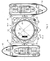
- FIG. 1 the lower part of a tower 2 is shown, which is anchored on a foundation 4 on the seabed 6.
- the tower 2 may be, for example, the tower of an offshore wind power station.
- a platform 10 is provided, which surrounds the tower 2 in the illustrated embodiment, in particular FIG. 2 lets recognize.
- the platform 10 may have different basic shapes. For example, it is conceivable to make the platform 10 circular or polygonal.
- FIG. 2 With regard to the basic form, two different embodiments are shown in each case in half, the according to FIG. 2 upper half represents a platform of rectangular basic shape and is denoted by the reference numeral "10-1" and the according to FIG.
- FIG. 1 is the platform 10 between a lower first position, the in FIG. 1 is denoted by “I”, and an upper second position which is in FIG. 1 is denoted by "II", mounted in the vertical direction along the tower 2 movable, with the aid of a lifting device described in more detail below.
- the lower first position I is the landing position in which at least one ship can dock on platform 10; in the figures, two ships 12 are shown by way of example, have moored diametrically opposite to the platform.
- the platform 10 has, in the illustrated embodiment, a welded pipe construction, which forms a framework, to suitcase occurring ramming abkoffern by mooring ships against the tower 2.
- FIG. 2 identifiable pairs of rods 14, 15, each of which is a rod 14 from a location adjacent to the center of the outside of the platform 10 tangent to one side of the wall 2a of the tower 2 and the other rod 15 from one adjacent to the center of the Outside of the platform 10 opposite location extends tangentially to the other side of the wall 2a of the tower 2, as FIG. 2 lets recognize.
- the platform 10 spans the tower 2 in several planes, which are designed in truss structure.
- the individual levels are interconnected by unspecified vertical pipe supports.
- additional pipe supports are additionally drawn diagonally from level to level.
- the top of the platform 10 is provided with unspecified carrier grates to make the platform 10 accessible. As a fall protection, the platform 10 is carried out to the sea side with a railing 16.
- each quadrant of the tower 2 is provided in the illustrated embodiment with two slide rails 18.
- the slide rails 18 form on its outer side sliding surfaces, wherein the slide rails 18 are arranged in the illustrated embodiment on the tower 2, that the sliding surfaces lie in a cylindrical plane to corresponding in an upper conical portion 2b of the tower 2 over the height of decreasing diameter compensate.
- each level of the platform 10 by a circumferential support ring 20 (see. FIG. 2 ) completed.
- This support ring is recessed only in the area of an emergency ladder, not shown on the tower 2 and serves as an abutment against the slide rails 18. Accordingly, the inner surface of the support rings 20 abuts against the slide rails 18 and thus is in sliding engagement with these.
- the carrier rings 20 are covered on their inner surfaces with appropriate suitable sliding material.
- the platform 10 is suspended in the illustrated embodiment on four tension cables 22, each via pulleys 24 in the interior of the tower. 2 be redirected.
- the pulleys 24 are arranged in the wall 2a of the tower 2 above the upper position II.
- non-illustrated inlet openings are formed there, through which the ropes 22 enter the interior of the tower 2.
- a traction cable 22 and an associated deflection roller 24 are provided on the tower 2 in each quadrant.
- the tower sleeve bushings are arranged for the four traction cables 22.
- the traction cables 22 are deflected to a drum winch 26, which is placed inside the tower 2, as in FIG. 2 is indicated.
- the winch 26 sits in the foot of the tower 2 above the foundation 4.
- the winch 26 is driven by a first electric motor, not shown.
- a second electric motor also not shown, is also provided in order to be able to drive the winch in the event of a fault in the first electric motor.
- the winch 26 should be designed so that in the event of power failure, the winch 26 can also be operated mechanically, eg by means of a hand crank.
- the winch 26 is further provided with a brake, not shown, in order to fix the platform 10 at any desired height between the lower position I and the upper position II.
- limit switches may be provided in the winch 26 to turn off the winch 26 when the platform 10 reaches one of the two positions I or II.
- the platform 10 is freely pivotable about the vertical longitudinal axis of the tower 2 over a limited angular range on both sides. Therefore, the traction cables 22 are rotatably mounted on the platform 10, so that even when pivoting the platform 10, caused by the application of a ship 12, the traction cables 22 do not rotate. For this purpose, as tension cables 22 also low-twist ropes are used.
- the winch 26 can be operated by means of a remote control from the ship 12 or from the platform 10. Furthermore, a third operating option can be provided on the tower 2.
- the tower 2 can also be arranged in the region of the lower position I stops not shown, on which the platform 10 comes to lie in its lower position I.
- the platform 10 In the upper position II, the platform 10 can be mechanically locked, by a locking device, not shown, whereby the traction cables 22 and the winch 26 are relieved.
- the platform 10 is equipped with a plurality of fenders 30 of different sizes.
- larger fenders are provided in the illustrated embodiments at the corners of the platform 10-1 and 10-2 than at intermediate points.
- the individual fenders 30 are cylindrical and rotatably mounted about vertical axes of rotation, so that when creating a ship 10, a part of the energy occurring by impact forces is converted into rotational energy and thus the tower 2 is not additionally burdened by torsional.
- the so-suggesting ship 12 turns off when driving in the right direction and minimizes the friction occurring during forward and backward movement of the ship 12.
- the fenders consist of a body of cell-closed plastic material whose hardness increases from outside to inside.
- the degree of hardness of Fenders 30 should be relatively soft, i. with a low Shore hardness, be designed to achieve the highest possible degree of compressibility. In this way, as much energy of the elastic shock should be absorbed in the fenders 30 in order to keep the load in the platform 10 and the tower 2 as low as possible.
- a vertical transfer ladder 32 (see. FIG. 1 ), which extends from the lower to the upper level of the platform 10 and is bounded laterally by vertical protective strips, not shown. Such a ladder 32 is intended to prevent trapping of persons when crossing the ship 12 to the platform 10.
- the carrier rings 20 are recessed in the region of an emergency conductor arranged on the tower 2, which is not shown in the figures.
- a ship picks up 12 service personnel at the port or from a larger work ship and relocates it to the job site.
- the platform 10 is moved from the upper position II, which usually forms the rest or stowed position, adjusted to one of the tides and the sea level adjusted height down.
- the skipper then maneuvers the vessel 12 from the optimal direction to the platform 10.
- the service personnel adjust a swell and climb the wave mountain on the ladder 32 on the platform 10 or directly on the platform 10, as in FIG. 1 is shown schematically.
- the platform 10 can of course be adjusted in height accordingly, the second position II forms the upper position.
- the tower 2 has an entrance door in the region of the upper position II in order to carry out further maintenance work there and also to be able to reach the interior of the tower 2.
- the platform 10 is in any case moved back to the upper position II, which, as already mentioned, also forms the rest or stowed position.
- the upper position II is located so far above the water surface, that the platform 10 of swell and Seeschlag can not be achieved.
Abstract
Description
Die Erfindung betrifft ein Wasserbauwerk mit einem turmförmigen Abschnitt und einer Vorrichtung zum Anlegen mindestens eines Wasserfahrzeuges am turmförmigen Abschnitt eines Wasserbauwerkes, wobei die Vorrichtung eine plattformartige Anlegestation aufweist und am Wasserbauwerk eine Hubeinrichtung zum Verfahren der Anlegestation angeordnet ist, so dass die Anlegestation zwischen einer ersten Position im Bereich der Wasseroberfläche zum Anlegen eines Wasserfahrzeuges und einer oberhalb der Wasseroberfläche befindlichen zweiten Position, in der das Anlegen eines Wasserfahrzeuges nicht möglich ist, entlang der Wandung des turmförmigen Abschnittes des Wasserbauwerkes verfahrbar und ferner zumindest in ihrer ersten Position um eine Drehachse, die etwa in Richtung der Bewegung der Anlegestation zwischen der ersten und der zweiten Position verläuft, zumindest in einem begrenzten Winkelbereich entlang der Wandung des turmförmigen Abschnittes des Wasserbauwerkes frei verschwenkbar ist.The invention relates to a hydraulic structure with a tower-shaped section and a device for applying at least one watercraft to the tower-shaped section of a hydraulic structure, wherein the device has a platform-like docking station and the hydraulic structure is arranged a lifting device for moving the docking station, so that the docking station between a first position in the area of the water surface for the application of a watercraft and a second position above the water surface, in which the application of a watercraft is not possible, along the wall of the tower-shaped portion of the hydraulic structure movable and further at least in its first position about an axis of rotation which is approximately in Direction of movement of the docking station between the first and the second position extends, at least in a limited angular range along the wall of the tower-shaped portion of the hydraulic structure is freely pivotable.
Anlegevorrichtungen für turmförmige Wasserbauwerke sind bereits bekannt. Üblicherweise befinden sich diese im Bereich der Wasseroberfläche, so dass eine Person von z. B. einem Schiff aus übersteigen kann und dann über eine Leiter, die an dem turmförmigen Wasserbauwerk nach oben führt, eine Serviceplattform oder bei Windkraftanlagen auch die Gondel erreicht. Für die Fälle, dass die Anlegevorrichtung aus irgendeinem Grund nicht erreicht werden kann, z. B. bei zu hohem Wellengang, kann zusätzlich eine Plattform an erhöhter Stelle am Wasserbauwerk zusätzlich vorgesehen sein, wo Personen von einem Helikopter aus mittels einer Seilwinde herabgelassen werden können. Der Einsatz von Helikoptern zu diesem Zweck ist aber sehr kostspielig, außerdem ist das Herablassen über eine Seilwinde gefährlich.Mooring devices for tower-shaped hydraulic structures are already known. Usually, these are in the water surface, so that a person of z. B. can exceed a ship and then via a ladder that leads up to the tower-shaped hydraulic structure, a service platform or wind turbines and the nacelle reached. In the event that the applicator can not be reached for some reason, e.g. B. in too high waves, in addition, a platform can be additionally provided at an elevated point on the hydraulic structure, where people can be lowered from a helicopter by means of a winch. The use of helicopters for this purpose is very expensive, in addition, the lowering over a winch is dangerous.
Aus der
Die
Eine ähnliche Schwenkbrückenanordnung ist in der
Die
Eine ähnliche Hubbrücke ist in der
Die
Vorgeschlagen wird nun erfindungsgemäß ein Wasserbauwerk mit einem turmförmigen Abschnitt und einer Vorrichtung zum Anlegen mindestens eines Wasserfahrzeuges am turmförmigen Abschnitt eines Wasserbauwerkes, wobei die Vorrichtung eine plattformartige Anlegestation aufweist und am Wasserbauwerk eine Hubeinrichtung zum Verfahren der Anlegestation angeordnet ist, so dass die Anlegestation zwischen einer ersten Position im Bereich der Wasseroberfläche zum Anlegen eines Wasserfahrzeuges und einer oberhalb der Wasseroberfläche befindlichen zweiten Position, in der das Anlegen eines Wasserfahrzeuges nicht möglich ist, entlang der Wandung des turmförmigen Abschnittes des Wasserbauwerkes verfahrbar und ferner zumindest in ihrer ersten Position um eine Drehachse, die etwa in Richtung der Bewegung der Anlegestation zwischen der ersten und der zweiten Position verläuft, zumindest in einem begrenzten Winkelbereich entlang der Wandung des turmförmigen Abschnittes des Wasserbauwerkes frei verschwenkbar ist, dadurch gekennzeichnet, dass die plattformartige Anlegestation den turmförmigen Abschnitt des Wasserbauwerks umschließt, wobei der turmförmige Abschnitt einen Kreisquerschnitt hat und/oder an dessen Wandung sich etwa in Bewegungsrichtung der Anlegestation erstreckende Gleitelemente so ausgebildet und angeordnet sind, dass deren Gleitflächen, mit denen sich die Anlegestation in Gleiteingriff befindet, im Wesentlichen in einer zylindrischen Ebene liegen oder tangential zu dieser ausgerichtet sind.According to the invention, a hydraulic structure with a tower-shaped section and a device for applying at least one watercraft to the tower-shaped section of a hydraulic structure is proposed, wherein the device has a platform-like docking station and a lifting device for moving the landing station is arranged on the hydraulic structure, so that the docking station between a first Position in the area of the water surface to create a vessel and one above the Water surface located second position in which the application of a watercraft is not possible, along the wall of the tower-shaped portion of the hydraulic structure movable and further at least in its first position about an axis of rotation which is approximately in the direction of movement of the landing station between the first and the second position runs, at least in a limited angular range along the wall of the tower-shaped portion of the hydraulic structure is freely pivotable, characterized in that the platform-like docking station surrounds the tower-shaped portion of the hydraulic structure, wherein the tower-shaped portion has a circular cross section and / or on the wall approximately in the direction of movement the landing station extending sliding elements are designed and arranged so that their sliding surfaces, with which the docking station is in sliding engagement, lie substantially in a cylindrical plane or aligned tangentially to this t are.
Demnach lässt sich mit Hilfe der Erfindung am turmförmigen Abschnitt eines Wasserbauwerkes eine Anlegevorrichtung realisieren, deren Anlegestation durch Verfahren in die zweite Position vor dem Seegang geschützt wird. Auf diese Weise ist die Anlegevorrichtung nicht permanentem Wellenschlag and Salzwasser ausgesetzt, wodurch das Material geschont und somit die Lebenszeit einer solchen Anlegevorrichtung erheblich verlängert werden kann. Außerdem wird aufgrund der verfahrbaren Anordnung der Anlegestation gemäß der Erfindung ein sicheres Ansteuern des Wasserbauwerks und somit ein gefahrloses Übersteigen einer Person von einem Schiff auf das Wasserbauwerk ermöglicht, indem die Anlegestation in Abhängigkeit von Wasserstand und Wellenhöhe auf die erste Position oder einer darüber liegenden Position entsprechend eingestellt werden kann.Accordingly, with the aid of the invention, at the tower-shaped section of a hydraulic structure, a landing device can be realized, the landing station of which is protected by methods in the second position from the sea state. In this way, the application device is not exposed to permanent waves and salt water, whereby the material is spared and thus the lifetime of such a docking device can be considerably extended. In addition, due to the movable arrangement of the landing station according to the invention, a safe driving of the hydraulic structure and thus a safe transfer of a person from a ship to the hydraulic structure allows by the mooring station depending on water level and wave height to the first position or an overlying position accordingly can be adjusted.
Ferner besteht keine direkte Schwenkverbindung zwischen der Anlegestation und dem Wasserbauwerk; die Anlegestation ist also am Wasserbauwerk nicht über ein Gelenk, Scharnier o. dgl. direkt angelenkt. Vielmehr ist nach der Lehre der Erfindung die Anlegestation gegenüber der entsprechenden Wandung des türmförmigen Abschnittes des Wasserbauwerkes zumindest in horizontaler Richtung frei bewegbar. Die freie Verschenkbarkeit wird ausschließlich durch die Anordnung an der Hubeinrichtung realisiert.Furthermore, there is no direct pivotal connection between the docking station and the hydraulic structure; the mooring station is therefore not articulated directly to the hydraulic structure via a joint, hinge or the like. Rather, according to the teachings of the invention, the docking station relative to the corresponding wall of the tower-shaped portion of the hydraulic structure, at least in the horizontal direction freely movable. The free Verschenkbarkeit is realized only by the arrangement of the lifting device.
Durch die erfindungsgemäße Aufhängung der Anlegestation wird die Oberflächenrauhigkeit der Wandung des Wasserbauwerkes nicht in unerwünschter Weise beeinflusst, da weder die Anlegestation noch die Hubeinrichtung sowie weitere Komponenten im Tauchbereich liegen.The inventive suspension of the landing station, the surface roughness of the wall of the hydraulic structure is not affected in an undesirable manner, since neither the docking station nor the lifting device and other components are in the diving area.
Anders als beispielsweise bei Schwenkbrücken wird auf das Wasserbauwerk kein Drehmoment in Schwerkraftrichtung ausgeübt, insbesondere wenn die Anlegestation zwischen der ersten und der zweiten Position verbracht wird. Dies wird erfindungsgemäß dadurch erreicht, dass die Anlegestation an einer Hubeinrichtung angeordnet ist, durch die die Anlegestation in ihrer Höhe zwischen der ersten und der zweiten Position entlang der Wandung des turmförmigen Abschnittes des Wasserbauwerkes verfahren wird. Bei dieser Bewegung handelt es sich also um eine im wesentlichen vertikale Hubbewegung. Eine Schwenkbewegung um eine horizontale Schwenkachse findet dagegen insoweit nicht statt; demnach ist auch kein entsprechendes Scharnier bzw. Gelenk am Wasserbauwerk vorgesehen und erforderlich, wodurch ansonsten die Statik des Wasserbauwerkes nachteilig beeinflusst würde.Unlike, for example, with swivel bridges, no torque is exerted on the hydraulic structure in the direction of gravity, in particular if the landing station is moved between the first and the second position. This is inventively achieved in that the application station is arranged on a lifting device by which the application station is moved in its height between the first and the second position along the wall of the tower-shaped portion of the hydraulic structure. This movement is therefore a substantially vertical lifting movement. A pivoting movement about a horizontal pivot axis, however, does not take place so far; Accordingly, no corresponding hinge or joint on the hydraulic structure is provided and required, which would otherwise adversely affect the statics of the hydraulic structure.
Ein weiterer - und besonders wichtiger - Vorteil durch die besondere Anordnung der Anlegestation gemäß der vorliegenden Erfindung besteht darin, dass eine nachgiebige Lagerung der Anlegestation in horizontaler Richtung geschaffen wird, wodurch bei insbesondere durch Anlegen eines Schiffes verursachten Stoßen mindestens ein Teil der dabei auftretenden Energie in Rotationsenergie umgewandelt und somit das Wasserbauwerk nicht durch zusätzliche Torsionsmomente belastet wird. Dies wird erfindungsgemäß dadurch erzielt, dass die Anlegestation an der Hubeinrichtung derart angeordnet wird, dass die Anlegestation zumindest in einem begrenzten Winkelbereich entlang der Wandung des turmförmigen Abschnittes des Wasserbauwerkes um eine Schwenk- bzw. Drehachse frei verschenkbar ist, die etwa in durch die Hubbewegung zwischen der ersten und der zweiten Position definierten Bewegungsrichtung der Anlegestation verläuft, ohne selbst ein Scharnier oder ein Gelenk zu bilden. Denn nach der Lehre der Erfindung besteht keine direkte Schwenkverbindung zwischen der Anlegestation und dem Wasserbauwerk. Vielmehr wird die freie Verschwenkbarkeit ausschließlich durch die Anordnung an der Hubeinrichtung realisiert.Another - and particularly important - advantage of the special arrangement of the landing station according to the present invention is that a resilient mounting of the landing station is provided in the horizontal direction, whereby at least a portion of the energy occurring in at Converted rotational energy and thus the hydraulic structure is not burdened by additional torsional moments. This is inventively achieved in that the docking station is arranged on the lifting device such that the landing station is freely verschenkbar at least in a limited angular range along the wall of the tower-shaped portion of the hydraulic structure about a pivot or rotation axis, approximately in by the lifting movement between The first and second position defined direction of movement of the landing station runs without even forming a hinge or a joint. Because according to the teaching of the invention there is no direct pivotal connection between the landing station and the hydraulic structure. Rather, the free pivoting is realized only by the arrangement of the lifting device.
Die zweite Position bildet insbesondere eine Ruheposition, in der sich die Anlegestation befindet, wenn sie nicht gebraucht wird, sondern außer Betrieb ist.The second position forms in particular a rest position in which the docking station is when it is not needed, but is out of order.
Vorzugsweise hängt die Anlegestation an der Hubeinrichtung. Gemäß einer bevorzugten Weiterbildung dieser Ausführung der Erfindung weist die Hubeinrichtung einen Seilzug auf, an dem die Anlegestation hängt. Hierzu weist gewöhnlich die Hubeinrichtung eine am Wasserbauwerk vorzusehende Umlenkeinrichtung, die vorzugsweise mindestens eine Umlenkrolle aufweist, zum Umlenken des Seilzuges und eine unterhalb der Umlenkeinrichtung innerhalb des Wasserbauwerkes anzuordnende Antriebseinrichtung zum Auf- und Abwickeln des Seilzuges auf, wobei es aus konstruktiven und statischen Erwägungen besonders vorteilhaft ist, die Antriebseinrichtung zur Anordnung im Bodenbereich, d.h. im Fuss oder auf dem Fundament, des Wasserbauwerkes vorzusehen.Preferably, the docking station hangs on the lifting device. According to a preferred embodiment of this embodiment of the invention, the lifting device on a cable on which hangs the docking station. For this purpose, the lifting device usually has a deflection device to be provided on the hydraulic structure, which preferably has at least one Has deflection pulley, for deflecting the cable and a below the deflection within the hydraulic structure to be arranged drive means for winding and unwinding of the cable, wherein it is particularly advantageous for structural and static considerations, the drive means for placement in the bottom area, ie in the foot or on the Foundation to provide the hydraulic structure.
Für den Fall, dass der turmförmige Abschnitt des Wasserbauwerkes einen Kreisquerschnitt hat, befindet sich gemäß einer weiteren bevorzugten Ausführungsform die Anlegevorrichtung in Gleiteingriff mit einer Wandung des Wasserbauwerkes und stützt sich, vorzugsweise mittels eines Gleit- und/oder Rollenlagers, an der Wandung ab.In the event that the tower-shaped section of the hydraulic structure has a circular cross section, according to a further preferred embodiment, the application device is in sliding engagement with a wall of the hydraulic structure and is supported on the wall, preferably by means of a sliding and / or roller bearing.
Vorzugsweise können sich die Gleitelemente etwa in Bewegungsrichtung der Anlegestation erstrecken. Hierzu können zweckmäßigerweise die Gleitelemente schienenförmige ausgebildet sein.Preferably, the sliding elements may extend approximately in the direction of movement of the docking station. For this purpose, the sliding elements can expediently be rail-shaped.
Gemäß einer weiteren bevorzugten Ausführungsform der Erfindung können die Gleitelemente so ausgebildet und angeordnet sein, dass deren Gleitflächen, mit denen sich die Anlegestation in Gleiteingriff befindet, im Wesentlichen über ihre gesamte Länge in Bewegungsrichtung der Anlegestation äquidistant zueinander angeordnet sind. Auf diese Weise können im Falle einer sich über die Höhe verändernden Form des Wasserbauwerkes die Gleitelemente als Abstandshalter dienen, um die Änderung der Form des Wasserbauwerkes entsprechend auszugleichen; dies gilt insbesondere für den Fall einer konischen Formgebung des Wasserbauwerkes, um den kleiner werdenden Durchmesser entsprechend auszugleichen.According to a further preferred embodiment of the invention, the sliding elements may be designed and arranged such that their sliding surfaces, with which the application station is in sliding engagement, are arranged substantially equidistant from one another over their entire length in the direction of movement of the application station. In this way, in the case of a height-varying shape of the hydraulic structure, the sliding elements can serve as spacers to compensate for the change in the shape of the hydraulic structure accordingly; This is especially true in the case of a conical shape of the hydraulic structure to compensate for the smaller diameter accordingly.
Gemäß einer weiteren besonders bevorzugten Ausführung weist die Anlegestation eine Fachwerkkonstruktion auf. Die durch ein anlegendes Schiff punktuell eingebrachten Stoßkräfte werden von einer Fachwerkkonstruktion aufgenommen und verteilt. Da sich die Stoßkräfte an den einzelnen Knotenpunkten der Fachwerkstäbe aufteilen und dadurch an mehreren Stellen verteilt auf das Wasserbauwerk einwirken, sind die Einzellasten für das Wasserbauwerk wesentlichen geringer als bei punktuellem Auftreffen. Ferner besitzt eine Fachwerkkonstruktion eine federnde Wirkung. Denn aufgrund der Elastizität der von der Fachwerkkonstruktion gebildeten Gitterkonstruktion und des dadurch relativ langen Verformungsweges wird das Wasserbauwerk im Falle eines Stoßes ebenfalls geschont. Schließlich besitzt eine Fachwerkkonstruktion ein relativ geringes Gewicht und bietet bei Seeschlag weniger Angriffsfläche als eine durchgehende Beplattung.According to a further particularly preferred embodiment, the landing station has a truss structure. The impact forces introduced punctually by a mooring ship are picked up and distributed by a truss structure. Since the impact forces at the individual nodes of the trusses divide and thereby act distributed at several points on the hydraulic structure, the individual loads for the hydraulic structure are substantially lower than at punctual impact. Furthermore, a truss structure has a spring effect. Because due to the elasticity of the truss structure formed by the truss structure and thereby relatively long deformation path, the hydraulic structure is also spared in the event of a shock. Finally, a truss structure has a relatively low weight and offers less attack surface in Seeschlag as a continuous plating.
Gemäß einer vorteilhaften Weiterbildung der zuvor erörterten Ausführung weist die Fachwerkkonstruktion mindestens einen Stab auf, der sich an der Wandung des Wasserbauwerkes vorbei, vorzugsweise tangential zu dieser, erstreckt. Dabei sollte sich der mindestens eine Stab etwa von der Anlegestelle aus erstrecken. Schließlich sollte zweckmäßigerweise mindestens ein Paar von Stäben vorgesehen sein, von denen sich der eine Stab von der Anlegestelle zur einen Seite der Wandung und der andere Stab von der Anlegestelle zur anderen Seite der Wandung des Wasserbauwerkes erstreckt. Eine solche Anordnung von Stäben ist besonders vorteilhaft zur Aufnahme von Stoßkräften, um diese dann in für das Wasserbauwerk besonders schonender Weise abzuleiten.According to an advantageous development of the previously discussed embodiment, the truss structure has at least one rod which extends past the wall of the hydraulic structure, preferably tangentially to the latter. In this case, the at least one rod should extend approximately from the landing. Finally, it is expedient to provide at least one pair of rods, of which one rod extends from the landing to one side of the wall and the other rod from the landing to the other side of the wall of the hydraulic structure. Such an arrangement of bars is particularly advantageous for absorbing impact forces in order to derive them in a particularly gentle manner for the hydraulic structure.
Nachfolgend werden bevorzugte Ausführungsbeispiele der Erfindung anhand der beiliegenden Zeichnungen näher erläutert. Es zeigen:
Figur 1- in Seitenansicht der untere Teil eines auf dem Meeresboden stehenden Turmes mit einer höhenverstellbaren Plattform, die in ihrer unteren Position vollständig und in ihrer oberen Position ausschnittsweise dargestellt ist, sowie mit zwei daran angelegten Schiffen; und
Figur 2- eine Draufsicht auf die Anordnung von
Figur 1
- FIG. 1
- in side view of the lower part of a standing on the seabed tower with a height-adjustable platform, which is shown in its lower position completely and in its upper position in sections, and with two ships attached to it; and
- FIG. 2
- a plan view of the arrangement of
FIG. 1 , wherein the tower is shown in sectional view.
In
Für Wartungsarbeiten am Turm 2 ist es notwendig, eine Anlegevorrichtung zu schaffen, die bei unterschiedlichen Wasserständen sowie in Abhängigkeit vom Wind, Wellen und Strömungen ein sicheres Anlegen eines Schiffes ermöglicht, um Wartungspersonal für Arbeiten am und im Turm 2 sicher übersetzen zu können. Hierzu ist eine Plattform 10 vorgesehen, die im dargestellten Ausführungsbeispiel den Turm 2 umschließt, wie insbesondere
wobei die gemäß
the according to
Die Plattform 10 weist im dargestellten Ausführungsbeispiel eine geschweißte Rohrkonstruktion auf, die ein Fachwerk bildet, um auftretende Rammstöße durch anlegende Schiffe gegenüber dem Turm 2 abzukoffern. In diesem Zusammenhang sei insbesondere auf die in
Im dargestellten Ausführungsbeispiel umspannt die Plattform 10 den Turm 2 in mehreren Ebenen, die in Fachwerkkonstruktion ausgeführt sind. Die einzelnen Ebenen sind untereinander durch nicht näher bezeichnete vertikale Rohrstützen verbunden. Um die Fachwerkkonstruktion der Plattform 10 verwindungssteifer zu machen, sind zusätzlich diagonal von Ebene zu Ebene weitere Rohrstützen eingezogen.In the illustrated embodiment, the
Die Oberseite der Plattform 10 ist mit nicht näher bezeichneten Trägerrosten versehen, um die Plattform 10 begehbar zu machen. Als Absturzsicherung ist die Plattform 10 zur Seeseite hin mit einem Geländer 16 ausgeführt.The top of the
Entlang des Turmes 2 sind mehrere Führungs- bzw. Gleitschienen 18 angebracht, die sich in vertikaler Richtung erstrecken, wie
Nach innen zum Turm 2 ist jede Ebene der Plattform 10 durch einen umlaufenden Trägerring 20 (vgl.
Um die Plattform 10 in der bereits erwähnten Weise in vertikaler Richtung zwischen der unteren Position I und der oberen Position II verfahrbar zu lagern, ist die Plattform 10 im dargestellten Ausführungsbeispiel an vier Zugseilen 22 aufgehängt, die jeweils über Umlenkrollen 24 in das Innere des Turmes 2 umgelenkt werden. Wie
Die Plattform 10 ist um die vertikale Längsachse des Turmes 2 über einen begrenzten Winkelbereich zu beiden Seiten hin frei verschwenkbar. Deshalb sind die Zugseile 22 an der Plattform 10 drehbar gelagert, so dass auch bei Verschwenken der Plattform 10, hervorgerufen durch Anlegen eines Schiffes 12, die Zugseile 22 sich nicht verdrehen. Hierzu sollten als Zugseile 22 ferner verdreharme Seile eingesetzt werden.The
Die Winde 26 kann mit Hilfe einer Fernbedienung vom Schiff 12 oder von der Plattform 10 aus bedient werden. Ferner kann eine dritte Bedienmöglichkeit am Turm 2 vorgesehen sein.The
Am Turm 2 können ferner im Bereich der unteren Position I nicht dargestellte Anschläge angeordnet sein, auf denen die Plattform 10 in ihrer unteren Position I zu liegen kommt. In der oberen Position II kann die Plattform 10 mechanisch verriegelt werden, und zwar durch eine nicht dargestellte Verriegelungseinrichtung, wodurch die Zugseile 22 und die Winde 26 entlastet werden.The
Zum sicheren Anlegen ist die Plattform 10 mit mehreren Fendern 30 unterschiedlicher Größe ausgerüstet. Dabei sind in den dargestellten Ausführungsbeispielen an den Ecken der Plattform 10-1 bzw. 10-2 größere Fender als an dazwischenliegenden Stellen vorgesehen. Die einzelnen Fender 30 sind zylindrisch ausgeführt und um vertikale Drehachsen drehbar gelagert, so dass beim Anlegen eines Schiffes 10 ein Teil der dabei durch Stoßkräfte auftretenden Energie in Rotationsenergie umgewandelt wird und somit der Turm 2 nicht zusätzlich durch Torsionsmomente belastet wird. Außerdem dreht das so anlegende Schiff 12 beim Weiterfahren in die richtige Richtung ab und wird die beim Vor- und Zurücksetzen des Schiffes 12 auftretende Reibung minimiert.For secure application, the
Vorzugsweise bestehen die Fender aus einem Körper aus zellgeschlossenem Kunststoffmaterial, dessen Härte von außen nach innen zunimmt. Generell sollte der Härtegrad der Fender 30 relativ weich, d.h. mit einer geringen Shorehärte, ausgebildet sein, um einen möglichst hohen Grad an Kompressibilität zu erzielen. Auf diese Weise soll möglichst viel Energie des elastischen Stoßes in den Fendern 30 aufgenommen werden, um die Belastung in der Plattform 10 und am Turm 2 so gering wie möglich zu halten.Preferably, the fenders consist of a body of cell-closed plastic material whose hardness increases from outside to inside. Generally, the degree of hardness of
An den vier Andockseiten der Plattform 10 ist jeweils mittig zwischen den Fendern 30 eine vertikale Übersteigleiter 32 (vgl.
Abschließend sei noch angemerkt, dass die Trägerringe 20 (vgl.
Für eine beabsichtigte Wartung des Turmes 2 nimmt ein Schiff 12 Servicepersonal im Hafen oder von einem größeren Arbeitsschiff auf und versetzt es zum Einsatzort. Vor Ort am Turm 2 wird die Plattform 10 von der oberen Position II, die im Regelfall auch die Ruhe- bzw. Stauposition bildet, auf eine der Tide und dem Seegang angepasste Höhe nach unten verfahren. Dann manövriert der Schiffsführer das Schiff 12 aus optimaler Richtung an die Plattform 10 heran. Danach passt das Servicepersonal einen Wellengang ab und steigt beim Wellenberg über auf die Leiter 32 an der Plattform 10 oder direkt auf die Plattform 10, wie in
Claims (12)
- Water-based structure with a tower-shaped portion and a device for landing at least one watercraft (12) at the tower-shaped portion of the water-based structure (2), wherein the device has a platform-like landing station (10) and a lifting mechanism (22, 24, 26) for displacing the landing station (10) is arranged at the water-based structure (2), so that the landing station (10) can be moved along the wall of the tower-shaped portion of the water-based structure (2) between a first position (I) in the region of the water surface to land a watercraft (13) and a second position (II) located above the water surface, in which it is not possible to land a watercraft (12), and furthermore, at least in its first position (I), can be freely pivoted about an axis of rotation, which extends approximately in the direction of the movement of the landing station (10) between the first and second position (I, II), at least in a limited angle range, along the wall of the tower-shaped portion of the water-based structure, characterised in that the platform-like landing station surrounds the tower-shaped portion of the water-based structure, wherein the tower-shaped portion has a circular cross section and/or, at the wall (2a) thereof, sliding elements (18) extending in the movement direction of the landing station (10) are configured and arranged in such a way that their sliding faces, with which the landing station (10) is in sliding engagement, are located in a cylindrical plane or are oriented tangentially with respect thereto.
- Water-based structure according to claim 1, characterised in that the second position (II) forms a rest position into which the landing station (10) is displaced when it is out of operation.
- Water-based structure according to claim 1 or 2, characterised in that the landing station (10) is suspended on the lifting mechanism (22, 24, 26).
- Water-based structure according to claim 3, characterised in that the lifting mechanism has a cable pull (22), on which the landing station (10) is suspended.
- Water-based structure according to claim 4, characterised in that the lifting mechanism has a deflection mechanism (24) arranged on the water-based structure (2), which preferably has at least one deflection roller to deflect the cable pull (22) and a drive mechanism (26) arranged below the deflection mechanism (24) inside the water-based structure (2) for winding and unwinding the cable pull (22).
- Water-based structure according to claim 5, characterised in that the drive mechanism (26) is arranged in the base region of the water-based structure (2).
- Water-based structure according to at least any one of the preceding claims, characterised in that if the tower-shaped portion has a circular cross section, the landing station (10) is supported by means of a sliding and/or roller bearing on the wall (2a) of the water-based structure (2).
- Water-based structure according to at least any ane of the preceding claims, characterised in that the sliding elements (18) are rail-shaped.
- water-based structure according to at least any one of the preceding claims, characterised in that the landing station (16) has a framework construction.
- water-based structure according to claim 9, characterised in that the framework construction has at least one bar (14, 15), which extends past the wall (2a) of the water-based structure (2), preferably tangentially with respect thereto.
- water-based structure according to claim 10, in which the landing station (10) has at least one landing location, characterised, in that the at least one bar (14, 15) extends approximately from the landing location.
- Water-based structure according to claim 11,
characterised by at least one pair of bars (14, 15), of which one bar (14) extends from the landing location to one side of the wall (2a) and the other bar (15) extends from the landing location to the other side of the wall (2a) of the water-based structure (2).
Applications Claiming Priority (3)
| Application Number | Priority Date | Filing Date | Title |
|---|---|---|---|
| DE20218481 | 2002-11-29 | ||
| DE20218481U | 2002-11-29 | ||
| PCT/EP2003/013404 WO2004051002A2 (en) | 2002-11-29 | 2003-11-28 | Device for landing a watercraft at a water-based structure |
Publications (2)
| Publication Number | Publication Date |
|---|---|
| EP1565619A2 EP1565619A2 (en) | 2005-08-24 |
| EP1565619B1 true EP1565619B1 (en) | 2008-07-30 |
Family
ID=32404480
Family Applications (1)
| Application Number | Title | Priority Date | Filing Date |
|---|---|---|---|
| EP03789101A Expired - Lifetime EP1565619B1 (en) | 2002-11-29 | 2003-11-28 | Device for landing a watercraft at a water-based structure |
Country Status (6)
| Country | Link |
|---|---|
| EP (1) | EP1565619B1 (en) |
| AT (1) | ATE403040T1 (en) |
| AU (1) | AU2003293740A1 (en) |
| DE (1) | DE50310262D1 (en) |
| DK (1) | DK1565619T3 (en) |
| WO (1) | WO2004051002A2 (en) |
Families Citing this family (5)
| Publication number | Priority date | Publication date | Assignee | Title |
|---|---|---|---|---|
| DE102004049733B4 (en) * | 2004-10-08 | 2006-09-21 | Universität Rostock | Procedures for minimizing the impact of recreational craft moorings and recreational boat crossings on sandy shores on coastal dynamics and the environment, in particular on lee erosion of the coast |
| AT506625B1 (en) | 2008-09-04 | 2009-10-15 | Palfinger Systems Gmbh | MAINTENANCE PLATFORM |
| DE102008048609A1 (en) * | 2008-09-23 | 2010-04-08 | Stefan Leske | Method for safe transfer of persons from ship to e.g. offshore-wind turbine, involves moving transfer element together with coupling to object and relative to another object based on relative movement of objects for vertical movement |
| DE102012007699A1 (en) * | 2012-04-19 | 2013-10-24 | WeserWind GmbH Offshore Construction Georgsmarienhütte | Method for transferring transfer ship to off-shore platform in transformer station integrated off-shore wind farm, involves utilizing floating transfer platform assigned to off-shore building, and adjusting height of transfer platform |
| CN108639256A (en) * | 2018-05-30 | 2018-10-12 | 西伯瀚(上海)海洋装备科技有限公司 | A kind of ocean platform steps on boat and box handling gear and ocean platform |
Family Cites Families (6)
| Publication number | Priority date | Publication date | Assignee | Title |
|---|---|---|---|---|
| AU425219B2 (en) * | 1971-08-04 | 1972-06-19 | The Fish Board | Wharf structure |
| US4003473A (en) * | 1974-08-30 | 1977-01-18 | Ryan Ramp, Inc. | Combined marine ramp transfer and mooring system |
| JPS54157951A (en) * | 1978-05-31 | 1979-12-13 | Hitachi Ltd | Automatic crane apparatus |
| US4590634A (en) * | 1984-12-20 | 1986-05-27 | The Boeing Company | Marine transfer device |
| US4740108A (en) * | 1986-07-24 | 1988-04-26 | Leonard Edward Levee | Method and apparatus for selecting and maintaining the level of a pier deck |
| US5803003A (en) * | 1997-01-02 | 1998-09-08 | The Louis Berkman Company | Rotary boat lift |
-
2003
- 2003-11-28 EP EP03789101A patent/EP1565619B1/en not_active Expired - Lifetime
- 2003-11-28 DE DE50310262T patent/DE50310262D1/en not_active Expired - Lifetime
- 2003-11-28 DK DK03789101T patent/DK1565619T3/en active
- 2003-11-28 WO PCT/EP2003/013404 patent/WO2004051002A2/en active IP Right Grant
- 2003-11-28 AT AT03789101T patent/ATE403040T1/en not_active IP Right Cessation
- 2003-11-28 AU AU2003293740A patent/AU2003293740A1/en not_active Abandoned
Also Published As
| Publication number | Publication date |
|---|---|
| WO2004051002A3 (en) | 2004-08-26 |
| EP1565619A2 (en) | 2005-08-24 |
| DE50310262D1 (en) | 2008-09-11 |
| AU2003293740A1 (en) | 2004-06-23 |
| ATE403040T1 (en) | 2008-08-15 |
| WO2004051002A2 (en) | 2004-06-17 |
| DK1565619T3 (en) | 2008-12-01 |
Similar Documents
| Publication | Publication Date | Title |
|---|---|---|
| DE60126984T2 (en) | METHOD AND DEVICE FOR ARRANGING AT LEAST ONE WIND TURBINE ON OPEN WATER | |
| DE2722747A1 (en) | PROCEDURE FOR ESTABLISHING AN OFFSHORE PLATFORM AND OFFSHORE PLATFORM | |
| DE2345274A1 (en) | LIFTING SEA PLATFORM | |
| EP2539219B1 (en) | Device for transporting and installing an arrangement of an offshore wind turbine comprising a raft foundation and method for transporting and installing such an arrangement having a raft foundation | |
| EP2591176B1 (en) | Offshore facility, in particular wind turbine | |
| DE102010020995B4 (en) | Foundation system for the foundation of an offshore wind energy plant | |
| DE2735619A1 (en) | FLOATING BODY WITH AT LEAST ONE WORK PLATFORM AND PROCEDURE FOR ITS ASSEMBLY | |
| EP3428345A1 (en) | Foundation for an offshore wind motor | |
| EP2623674A1 (en) | Substructure for an offshore platform and method for installing same | |
| DE102005053782B4 (en) | Self-climbing device | |
| EP1565619B1 (en) | Device for landing a watercraft at a water-based structure | |
| EP2383219B1 (en) | Method for producing a lifting device on a platform | |
| DE3312010A1 (en) | DEVICE AND METHOD FOR LOADING AND UNLOADING LIGHTERS ON OR FROM SHIPS | |
| EP1321671B1 (en) | Barge for the transport of offshore wind turbines | |
| DE1276304B (en) | Portal crane with foldable trolley jib | |
| EP1634998A1 (en) | Transport and foundation of functional units, in particular offshore wind turbines. | |
| EP4127453A1 (en) | Device and method for erecting a wind turbine with a tower and two booms extending from the tower | |
| WO2019170831A1 (en) | Boat lift | |
| DE2646134C2 (en) | Offshore platform | |
| DE1807959A1 (en) | Ship landing stage | |
| EP1384883A1 (en) | Lifting barge for transporting offshore wind turbines | |
| DE3001735C2 (en) | Device for the automatic assembly and disassembly of a pontoon consisting of several container parts | |
| DE19833184C2 (en) | Container bridge with height-adjustable bridge girder | |
| DE2725651C2 (en) | Device for supporting climbing poles interacting with so-called climbing winches | |
| DE102016109004A1 (en) | float |
Legal Events
| Date | Code | Title | Description |
|---|---|---|---|
| PUAI | Public reference made under article 153(3) epc to a published international application that has entered the european phase |
Free format text: ORIGINAL CODE: 0009012 |
|
| 17P | Request for examination filed |
Effective date: 20050527 |
|
| AK | Designated contracting states |
Kind code of ref document: A2 Designated state(s): AT BE BG CH CY CZ DE DK EE ES FI FR GB GR HU IE IT LI LU MC NL PT RO SE SI SK TR |
|
| AX | Request for extension of the european patent |
Extension state: AL LT LV MK |
|
| DAX | Request for extension of the european patent (deleted) | ||
| 17Q | First examination report despatched |
Effective date: 20050912 |
|
| GRAP | Despatch of communication of intention to grant a patent |
Free format text: ORIGINAL CODE: EPIDOSNIGR1 |
|
| GRAS | Grant fee paid |
Free format text: ORIGINAL CODE: EPIDOSNIGR3 |
|
| GRAA | (expected) grant |
Free format text: ORIGINAL CODE: 0009210 |
|
| AK | Designated contracting states |
Kind code of ref document: B1 Designated state(s): AT BE BG CH CY CZ DE DK EE ES FI FR GB GR HU IE IT LI LU MC NL PT RO SE SI SK TR |
|
| REG | Reference to a national code |
Ref country code: GB Ref legal event code: FG4D Free format text: NOT ENGLISH |
|
| REG | Reference to a national code |
Ref country code: CH Ref legal event code: EP |
|
| REF | Corresponds to: |
Ref document number: 50310262 Country of ref document: DE Date of ref document: 20080911 Kind code of ref document: P |
|
| REG | Reference to a national code |
Ref country code: IE Ref legal event code: FG4D Free format text: LANGUAGE OF EP DOCUMENT: GERMAN |
|
| REG | Reference to a national code |
Ref country code: DK Ref legal event code: T3 |
|
| PG25 | Lapsed in a contracting state [announced via postgrant information from national office to epo] |
Ref country code: ES Free format text: LAPSE BECAUSE OF FAILURE TO SUBMIT A TRANSLATION OF THE DESCRIPTION OR TO PAY THE FEE WITHIN THE PRESCRIBED TIME-LIMIT Effective date: 20081110 Ref country code: NL Free format text: LAPSE BECAUSE OF FAILURE TO SUBMIT A TRANSLATION OF THE DESCRIPTION OR TO PAY THE FEE WITHIN THE PRESCRIBED TIME-LIMIT Effective date: 20080730 Ref country code: PT Free format text: LAPSE BECAUSE OF FAILURE TO SUBMIT A TRANSLATION OF THE DESCRIPTION OR TO PAY THE FEE WITHIN THE PRESCRIBED TIME-LIMIT Effective date: 20081230 |
|
| PG25 | Lapsed in a contracting state [announced via postgrant information from national office to epo] |
Ref country code: FI Free format text: LAPSE BECAUSE OF FAILURE TO SUBMIT A TRANSLATION OF THE DESCRIPTION OR TO PAY THE FEE WITHIN THE PRESCRIBED TIME-LIMIT Effective date: 20080730 Ref country code: BG Free format text: LAPSE BECAUSE OF FAILURE TO SUBMIT A TRANSLATION OF THE DESCRIPTION OR TO PAY THE FEE WITHIN THE PRESCRIBED TIME-LIMIT Effective date: 20081030 Ref country code: SI Free format text: LAPSE BECAUSE OF FAILURE TO SUBMIT A TRANSLATION OF THE DESCRIPTION OR TO PAY THE FEE WITHIN THE PRESCRIBED TIME-LIMIT Effective date: 20080730 |
|
| REG | Reference to a national code |
Ref country code: IE Ref legal event code: FD4D |
|
| PG25 | Lapsed in a contracting state [announced via postgrant information from national office to epo] |
Ref country code: IE Free format text: LAPSE BECAUSE OF FAILURE TO SUBMIT A TRANSLATION OF THE DESCRIPTION OR TO PAY THE FEE WITHIN THE PRESCRIBED TIME-LIMIT Effective date: 20080730 Ref country code: EE Free format text: LAPSE BECAUSE OF FAILURE TO SUBMIT A TRANSLATION OF THE DESCRIPTION OR TO PAY THE FEE WITHIN THE PRESCRIBED TIME-LIMIT Effective date: 20080730 |
|
| PG25 | Lapsed in a contracting state [announced via postgrant information from national office to epo] |
Ref country code: RO Free format text: LAPSE BECAUSE OF FAILURE TO SUBMIT A TRANSLATION OF THE DESCRIPTION OR TO PAY THE FEE WITHIN THE PRESCRIBED TIME-LIMIT Effective date: 20080730 Ref country code: SK Free format text: LAPSE BECAUSE OF FAILURE TO SUBMIT A TRANSLATION OF THE DESCRIPTION OR TO PAY THE FEE WITHIN THE PRESCRIBED TIME-LIMIT Effective date: 20080730 Ref country code: CZ Free format text: LAPSE BECAUSE OF FAILURE TO SUBMIT A TRANSLATION OF THE DESCRIPTION OR TO PAY THE FEE WITHIN THE PRESCRIBED TIME-LIMIT Effective date: 20080730 |
|
| BERE | Be: lapsed |
Owner name: FR. FASSMER G.M.B.H. & CO. KG Effective date: 20081130 |
|
| PLBE | No opposition filed within time limit |
Free format text: ORIGINAL CODE: 0009261 |
|
| STAA | Information on the status of an ep patent application or granted ep patent |
Free format text: STATUS: NO OPPOSITION FILED WITHIN TIME LIMIT |
|
| PG25 | Lapsed in a contracting state [announced via postgrant information from national office to epo] |
Ref country code: MC Free format text: LAPSE BECAUSE OF NON-PAYMENT OF DUE FEES Effective date: 20081130 |
|
| REG | Reference to a national code |
Ref country code: CH Ref legal event code: PL |
|
| REG | Reference to a national code |
Ref country code: DK Ref legal event code: EBP |
|
| 26N | No opposition filed |
Effective date: 20090506 |
|
| REG | Reference to a national code |
Ref country code: CH Ref legal event code: AEN Free format text: DAS PATENT IST AUFGRUND DES WEITERBEHANDLUNGSANTRAGS VOM 10.07.2009 REAKTIVIERT WORDEN. Ref country code: CH Ref legal event code: NV Representative=s name: RENTSCH & PARTNER |
|
| PG25 | Lapsed in a contracting state [announced via postgrant information from national office to epo] |
Ref country code: IT Free format text: LAPSE BECAUSE OF FAILURE TO SUBMIT A TRANSLATION OF THE DESCRIPTION OR TO PAY THE FEE WITHIN THE PRESCRIBED TIME-LIMIT Effective date: 20080730 |
|
| REG | Reference to a national code |
Ref country code: FR Ref legal event code: ST Effective date: 20090731 |
|
| PG25 | Lapsed in a contracting state [announced via postgrant information from national office to epo] |
Ref country code: BE Free format text: LAPSE BECAUSE OF NON-PAYMENT OF DUE FEES Effective date: 20081130 |
|
| PG25 | Lapsed in a contracting state [announced via postgrant information from national office to epo] |
Ref country code: LI Free format text: LAPSE BECAUSE OF NON-PAYMENT OF DUE FEES Effective date: 20081130 Ref country code: DK Free format text: LAPSE BECAUSE OF NON-PAYMENT OF DUE FEES Effective date: 20081130 Ref country code: DE Free format text: LAPSE BECAUSE OF NON-PAYMENT OF DUE FEES Effective date: 20090603 Ref country code: CH Free format text: LAPSE BECAUSE OF NON-PAYMENT OF DUE FEES Effective date: 20081130 |
|
| PGFP | Annual fee paid to national office [announced via postgrant information from national office to epo] |
Ref country code: CH Payment date: 20090729 Year of fee payment: 6 |
|
| REG | Reference to a national code |
Ref country code: FR Ref legal event code: RN |
|
| REG | Reference to a national code |
Ref country code: FR Ref legal event code: FC |
|
| PG25 | Lapsed in a contracting state [announced via postgrant information from national office to epo] |
Ref country code: AT Free format text: LAPSE BECAUSE OF NON-PAYMENT OF DUE FEES Effective date: 20081128 Ref country code: SE Free format text: LAPSE BECAUSE OF FAILURE TO SUBMIT A TRANSLATION OF THE DESCRIPTION OR TO PAY THE FEE WITHIN THE PRESCRIBED TIME-LIMIT Effective date: 20081030 |
|
| REG | Reference to a national code |
Ref country code: DK Ref legal event code: EGE |
|
| REG | Reference to a national code |
Ref country code: CH Ref legal event code: PL |
|
| PG25 | Lapsed in a contracting state [announced via postgrant information from national office to epo] |
Ref country code: HU Free format text: LAPSE BECAUSE OF FAILURE TO SUBMIT A TRANSLATION OF THE DESCRIPTION OR TO PAY THE FEE WITHIN THE PRESCRIBED TIME-LIMIT Effective date: 20090131 Ref country code: LU Free format text: LAPSE BECAUSE OF NON-PAYMENT OF DUE FEES Effective date: 20081128 Ref country code: CY Free format text: LAPSE BECAUSE OF FAILURE TO SUBMIT A TRANSLATION OF THE DESCRIPTION OR TO PAY THE FEE WITHIN THE PRESCRIBED TIME-LIMIT Effective date: 20080730 |
|
| PGRI | Patent reinstated in contracting state [announced from national office to epo] |
Ref country code: DE Effective date: 20100426 |
|
| PG25 | Lapsed in a contracting state [announced via postgrant information from national office to epo] |
Ref country code: CH Free format text: LAPSE BECAUSE OF NON-PAYMENT OF DUE FEES Effective date: 20091130 Ref country code: TR Free format text: LAPSE BECAUSE OF FAILURE TO SUBMIT A TRANSLATION OF THE DESCRIPTION OR TO PAY THE FEE WITHIN THE PRESCRIBED TIME-LIMIT Effective date: 20080730 Ref country code: LI Free format text: LAPSE BECAUSE OF NON-PAYMENT OF DUE FEES Effective date: 20091130 |
|
| PG25 | Lapsed in a contracting state [announced via postgrant information from national office to epo] |
Ref country code: GR Free format text: LAPSE BECAUSE OF FAILURE TO SUBMIT A TRANSLATION OF THE DESCRIPTION OR TO PAY THE FEE WITHIN THE PRESCRIBED TIME-LIMIT Effective date: 20081031 |
|
| REG | Reference to a national code |
Ref country code: FR Ref legal event code: PLFP Year of fee payment: 13 |
|
| PGFP | Annual fee paid to national office [announced via postgrant information from national office to epo] |
Ref country code: GB Payment date: 20151123 Year of fee payment: 13 Ref country code: DK Payment date: 20151124 Year of fee payment: 13 Ref country code: DE Payment date: 20151208 Year of fee payment: 13 |
|
| PGFP | Annual fee paid to national office [announced via postgrant information from national office to epo] |
Ref country code: FR Payment date: 20151124 Year of fee payment: 13 |
|
| REG | Reference to a national code |
Ref country code: DE Ref legal event code: R119 Ref document number: 50310262 Country of ref document: DE |
|
| REG | Reference to a national code |
Ref country code: DK Ref legal event code: EBP Effective date: 20161130 Ref country code: DK Ref legal event code: EBP Effective date: 20081130 |
|
| GBPC | Gb: european patent ceased through non-payment of renewal fee |
Effective date: 20161128 |
|
| REG | Reference to a national code |
Ref country code: FR Ref legal event code: ST Effective date: 20170731 |
|
| PG25 | Lapsed in a contracting state [announced via postgrant information from national office to epo] |
Ref country code: FR Free format text: LAPSE BECAUSE OF NON-PAYMENT OF DUE FEES Effective date: 20161130 |
|
| PG25 | Lapsed in a contracting state [announced via postgrant information from national office to epo] |
Ref country code: DE Free format text: LAPSE BECAUSE OF NON-PAYMENT OF DUE FEES Effective date: 20170601 Ref country code: GB Free format text: LAPSE BECAUSE OF NON-PAYMENT OF DUE FEES Effective date: 20161128 Ref country code: DK Free format text: LAPSE BECAUSE OF NON-PAYMENT OF DUE FEES Effective date: 20161130 |