EP1564857B1 - Metallgehäuse, insbesondere für elektrische Geräte - Google Patents
Metallgehäuse, insbesondere für elektrische Geräte Download PDFInfo
- Publication number
- EP1564857B1 EP1564857B1 EP05100691A EP05100691A EP1564857B1 EP 1564857 B1 EP1564857 B1 EP 1564857B1 EP 05100691 A EP05100691 A EP 05100691A EP 05100691 A EP05100691 A EP 05100691A EP 1564857 B1 EP1564857 B1 EP 1564857B1
- Authority
- EP
- European Patent Office
- Prior art keywords
- corner
- box according
- lid
- land
- fixing screw
- Prior art date
- Legal status (The legal status is an assumption and is not a legal conclusion. Google has not performed a legal analysis and makes no representation as to the accuracy of the status listed.)
- Expired - Lifetime
Links
- 239000002184 metal Substances 0.000 title claims description 10
- 230000007704 transition Effects 0.000 claims description 13
- 230000000295 complement effect Effects 0.000 claims description 3
- 238000007789 sealing Methods 0.000 claims description 3
- 238000003780 insertion Methods 0.000 claims description 2
- 230000037431 insertion Effects 0.000 claims description 2
- 230000000149 penetrating effect Effects 0.000 claims description 2
- 230000000694 effects Effects 0.000 claims 1
- 208000031968 Cadaver Diseases 0.000 description 8
- 210000000056 organ Anatomy 0.000 description 3
- 238000004519 manufacturing process Methods 0.000 description 2
- 238000003466 welding Methods 0.000 description 2
- 241001644893 Entandrophragma utile Species 0.000 description 1
- 230000006978 adaptation Effects 0.000 description 1
- 238000004026 adhesive bonding Methods 0.000 description 1
- 238000012423 maintenance Methods 0.000 description 1
- 239000000463 material Substances 0.000 description 1
- 238000000034 method Methods 0.000 description 1
Images



Classifications
-
- H—ELECTRICITY
- H02—GENERATION; CONVERSION OR DISTRIBUTION OF ELECTRIC POWER
- H02G—INSTALLATION OF ELECTRIC CABLES OR LINES, OR OF COMBINED OPTICAL AND ELECTRIC CABLES OR LINES
- H02G3/00—Installations of electric cables or lines or protective tubing therefor in or on buildings, equivalent structures or vehicles
- H02G3/02—Details
- H02G3/08—Distribution boxes; Connection or junction boxes
- H02G3/14—Fastening of cover or lid to box
-
- H—ELECTRICITY
- H02—GENERATION; CONVERSION OR DISTRIBUTION OF ELECTRIC POWER
- H02G—INSTALLATION OF ELECTRIC CABLES OR LINES, OR OF COMBINED OPTICAL AND ELECTRIC CABLES OR LINES
- H02G3/00—Installations of electric cables or lines or protective tubing therefor in or on buildings, equivalent structures or vehicles
- H02G3/02—Details
- H02G3/08—Distribution boxes; Connection or junction boxes
- H02G3/081—Bases, casings or covers
-
- H—ELECTRICITY
- H02—GENERATION; CONVERSION OR DISTRIBUTION OF ELECTRIC POWER
- H02G—INSTALLATION OF ELECTRIC CABLES OR LINES, OR OF COMBINED OPTICAL AND ELECTRIC CABLES OR LINES
- H02G3/00—Installations of electric cables or lines or protective tubing therefor in or on buildings, equivalent structures or vehicles
- H02G3/02—Details
- H02G3/08—Distribution boxes; Connection or junction boxes
- H02G3/088—Dustproof, splashproof, drip-proof, waterproof, or flameproof casings or inlets
-
- H—ELECTRICITY
- H05—ELECTRIC TECHNIQUES NOT OTHERWISE PROVIDED FOR
- H05K—PRINTED CIRCUITS; CASINGS OR CONSTRUCTIONAL DETAILS OF ELECTRIC APPARATUS; MANUFACTURE OF ASSEMBLAGES OF ELECTRICAL COMPONENTS
- H05K5/00—Casings, cabinets or drawers for electric apparatus
- H05K5/10—Casings, cabinets or drawers for electric apparatus comprising several parts forming a closed casing
- H05K5/13—Casings, cabinets or drawers for electric apparatus comprising several parts forming a closed casing assembled by screws
Definitions
- the present invention relates to a metal box for housing electrical members, the box comprising a substantially parallelepiped body to be closed by a cover by means of screws or hinge parts placed at the corners.
- cover will mean both a door and a lid itself.
- Some known boxes for housing electrical organs have a lid which is provided at the corners of hinge parts or parts to be screwed or fixed by quarter turn rotation. These parts are engaged in holes provided at the respective corners of the lid.
- the manufacturer of the box must provide a large number of covers depending on the various types or sizes of screws desired by the user.
- the purpose of the invention is to simplify the production of a metal cover to be sealed to the body of a box for electrical components, and which allows a simple and inexpensive way to visually differentiate the cover and easy adaptation to different types of fixing screws.
- the receiving member which cooperates with the screw and houses a portion does not protrude into the body or forms a negligible projection under the triangular angle range.
- the volume located inside the body under the angle range is therefore completely or almost completely usable for housing elements in the box.
- the opinion fixing the cover can be threaded or quarter-turn type and the receiving element is adapted to lock this screw in the closed position.
- At least one corner of the body is provided for the oblique transition edge and the associated angle range to be stamped with the rest of the body.
- the oblique transition edge and the associated angle range are folded from a side wall of the body and are welded to the adjacent wall and the return and erect edge of the adjacent wall. body.
- the oblique transition edge and the associated angle range are provided on an angle piece, of generally triangular shape, attached and sealingly attached to the return and erect edges of the walls forming the respective corner.
- the angle range may have a through passage that communicates with the interior of the body, and the receiving element is then a blind insert having a flange fixed to the angle range and a blind tube penetrating the internal space of the body on a low height below the range, the insert being provided with internal shapes for tightening the screw by threading or quarter turn.
- the angle range may be devoid of through passage.
- the receiving element can then be a blind hole stamped in the angle range and provided with an internal screw thread for the fixing screw. It can also be constituted by a nut-shaped part, this nut piece having a flat shape in particular an inverted U-shape, provided with a threaded-hole core adapted to cooperate with the fastening screw and fastening lugs. the outer face of the corner range.
- the illustrated box on Figures 1 and 2 is a metal box intended to contain electrical control, control or connection components. It consists of a body 10 of generally parallelepipedal, or quadrangular, shape and a cover 20 intended to be laid and sealingly attached to the body 10.
- the body 10 has a horizontal bottom and four side walls 13.
- the bottom 12 is provided with elements not shown for fixing the box to a support and the body of the box defines the opposite of the bottom an opening 14 on the edge of which the lid 20 must be applied.
- Each side wall 13 is folded along a horizontal edge 13d to form a horizontal return of small width 13e ( figure 7 ). At the 13th return is connected a rectilinear edge 15 erected vertically.
- the terms "horizontal” and “vertical” are used herein for simplicity and are understood by reference to the figures.
- the body 10 has a horizontal angle area 16 adjacent to an edge 17 erected substantially vertically.
- the range 16 is substantially triangular and interconnects the returns 13e adjacent walls, while the edge 17 interconnects the erected edges 15 of the walls 13a, 13b, thus forming between these edges an oblique transition, for example 45 ° .
- the succession of edges 15 and 17 constitutes an octagonal contour which defines the opening 14 and whose upper edge forms a support for a seal (26, figure 6 ) of the cover 20.
- the cover 20 is composed for its part a thin rectangular metal plate 22 and four corner pieces 30, these parts being of any suitable material.
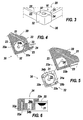
- the plate 22 is extended on its periphery by folded edges 23 and, at the four corners, it has through openings 24 ( figure 5 ) cut in order to receive the corner pieces 30.
- the edges 23 have, on the inner side and at the opening 24, corner areas 23a ( Figures 5 and 6 ) ensuring the maintenance of the corner piece 30; the zones 23a can for this purpose be provided with assembly forms 23b for example recessed.
- the corner piece 30 serves to cover the corner area of the edges 23.
- the part 30 has an upper wall 31 which forms a support bracket 31a ( figure 5 ) on a corresponding area 22a of the upper face of the plate 22.
- the corner piece 30 also has a side wall 32, of a shape adapted to that of the edges 23.
- the wall 32 is as a dihedron with two faces 32a orthogonal to each other and to the upper wall 31.
- the corner piece 30 has a wall 32 of left shape adapted to this curved shape.
- the faces 32a of the dihedron have forms 32b of complementary assembly of the shapes 23b.
- the corner piece 30 also has a cylindrical stud 33 ( Figures 4 and 5 ) ensuring the interlocking in the opening 24 and having a housing 34 for a screw 41 for fixing the cover 20 on the body 10 of the box.
- Fixing the corner piece 30 may alternatively be made by pinching on the cover 20, by means of a suitable clevis.
- the pinch yoke can be combined with the assembly forms 32b.
- the fixing screw 41 ( figure 10 ) has a head 41a housed in a portion 34a of the housing 34 and a rod 41b threaded or hook-shaped, guided in the passage 34b.
- the screw 41 has an axis perpendicular to the plane of the plate 22 and is introduced along this axis in the corner piece 30.
- the corner piece 30 is fixed on the bearing surface 22a of the plate 22 and against the edges 23 by clipping, gluing, riveting or other similar method of attachment.
- the added corner pieces can easily be differentiated to vary the appearance of the lid, while allowing to add to the same metal plate 22 clamping elements - screws or quarter-turn elements - with various imprints, the studs 33 having a shape and a housing 34 adapted to these various clamping elements.
- the realization of the angle range and the corresponding transition edge can be effected in different ways.
- the range 16 and the transition edge 17 do not mark any discontinuity with the returns 13e and the edges 15, because the body portion located towards the lid is obtained in one piece by stamping.
- Part 10a is assembled in Part 10b (see line of seal figure 2 ) by any appropriate means.
- a specific angle piece 18, for example stamped, comprising the triangular beach 16 and the upright edge 17, is attached in a corresponding cut-out corner of the body 10.
- the corner piece 18 is for example welded on the one hand to the 13th returns, in particular along horizontal lines 18a parallel to the walls 13 (and to the horizontal edges 13d), and secondly to the edges 15 along vertical lines 18b.
- the angle piece 18 may also have wings inserted under the returns 13e, these wings may optionally be supported on the inner faces of the walls 13a, 13b.
- one of the walls for example the wall 13b, determining a wedge, provides a flap 19 which has just cut and extends its return 13e to form the angle range 16.
- the flap 19 can be folded to produce the edge oblique 17, or otherwise it may be provided as an extension of the erect edge 15 of the adjacent wall 13a.
- the application of the flap 19 is sealed for example by welding its side 19a at the end of the horizontal edge 13d, and its front edge 19b (perpendicular to the side 19a) to the return 13e of the wall 13a.
- the edge 17, as a folded extension of the edge 15 of the wall 13a is welded on the one hand to the edge 15 of the wall 13b and on the other hand to the horizontal surface of the beach 16.
- the sealing of the lid 20 to the body 10 is effected by means of devices 40 for screw fixing associated with the angle ranges 16 and does not alter the internal space of the box.
- the screws 41 associated with the cover 20 may be, as the case may be, quarter-turn fasteners or threaded screws.
- the axes of rotation of the screws are indicated in phantom in the figures.
- the arrangement adopted according to the invention makes it easy to change the screws 41, depending on the desired impression profile for their head: cruciform, double bar, square, triangle, etc.
- a passage opening 16a is provided in the angle range 16 and a blind insert 42 is inserted into this orifice.
- the blind insert 42 has a blind sleeve 42c having a hole 42a for example threaded with which the screw cooperates, and a flange 42b for sealingly fastening, for example by welding, to the angle range 16.
- a stamping operation performed on the tracks 16 creates a blind form 44 similar to an insert 42, this shape being shallow and threaded at 44a to receive the screw 41.
- no passage opening is provided in the angle range 16.
- a clamping piece 43 in particular a nut function, is placed on the track 16, this piece having a generally flat shape, for example U-shaped overturned .
- the piece 43 has a horizontal core 43a provided with a threaded hole 43b, wings 43c and tabs 43d attachment to the upper face of the angle range 16.
- the height of the wings 43c is such that the screw 41 associated with the cover 20 can perform its clamping stroke.
Landscapes
- Engineering & Computer Science (AREA)
- Architecture (AREA)
- Civil Engineering (AREA)
- Structural Engineering (AREA)
- Microelectronics & Electronic Packaging (AREA)
- Casings For Electric Apparatus (AREA)
Claims (17)
- Metallisches Gehäuse, insbesondere für elektrische Organe, das einen im Wesentlichen parallelepipedischen Körper (10) aufweist, der von einem Deckel, einer Tür oder einem analogen metallischen Organ (20) mit Hilfe von Befestigungsschrauben (41) verschließbar ist, die an den Ecken angeordnet sind, wobei der Körper (10) vier ebene Seitenwände (13) und eine stirnseitige Öffnung aufweist, wobei Aufnahmen (34) für die Befestigungsschrauben (41) an den Ecken des Deckels (20) vorgesehen sind,
dadurch gekennzeichnet, dass- der Deckel (20) eine dünne Platte (22) mit Umbördelungen (23) aufweist, wobei die Platte an den Ecken mit ausgeschnittenen Durchgangsöffnungen (24) versehen ist, die größer sind als die Aufnahmen der Köpfe der Befestigungsschrauben,- der Deckel (20) Eckbeschläge (30) aufweist, die über der Platte (22) aufgesetzt sind, um die Durchgangsöffnungen zu bedecken, indem sie von einer Leiste (31) auf die Oberseite (22a) der Platte aufgelegt werden,- jeder Eckbeschlag (30) eine Aufnahme (34) aufweist, die für eine Einführung der jeweiligen Befestigungsschraube (41) gemäß ihrer Achse geeignet ist. - Gehäuse nach Anspruch 1, dadurch gekennzeichnet, dass die Durchgangsöffnung (24) der dünnen Platte (22) von Winkelzonen (23a) der Umbördelungen (23) begrenzt wird.
- Gehäuse nach Anspruch 1, dadurch gekennzeichnet, dass der Eckbeschlag (30) eine Seitenwand (32) aufweist, die die Winkelzonen (23a) der Umbördelungen (23) des Deckels (20) bedeckt.
- Gehäuse nach Anspruch 3, dadurch gekennzeichnet, dass die Seitenwand (32) nach innen Montageformen (32b) aufweist, die mit komplementären Formen (23b) zusammenwirken, die in den Winkelzonen (23a) der Umbördelungen (23) vorgesehen sind.
- Gehäuse nach Anspruch 3, dadurch gekennzeichnet, dass die Seitenwand (32) ein Dieder (31) bildet.
- Gehäuse nach Anspruch 1, dadurch gekennzeichnet, dass der Eckbeschlag (30) eine Aufnahme (34) aufweist, die an den Typ der Befestigungsschraube (41) angepasst ist.
- Gehäuse nach Anspruch 6, dadurch gekennzeichnet, dass der Eckbeschlag (30) eine Seitenwand (32) aufweist, die die Winkelzonen (23a) der Umbördelungen (23) des Deckels (20) bedeckt, und dass die an den Typ der Befestigungsschraube angepasste Aufnahme (34) in einem Block (33) derart ausgebildet ist, dass die Winkelzonen (23a) der Umbördelungen (23) des Deckels zwischen den Block (33) und die Seitenwand (32) eingefügt oder eingepasst werden.
- Gehäuse nach einem der Ansprüche 1 bis 7, dadurch gekennzeichnet, dass,- die stirnseitige Öffnung seines Körpers (10) von einem durchgehenden Rahmen begrenzt wird, der von Rücksprüngen (13e) seiner Seitenwände (13) gebildet wird, wobei jeder Rücksprung sich durch einen geradlinigen Rand (15) verlängert, der im Wesentlichen parallel zur Wand hochsteht,- die Enden der hochstehenden Ränder (15), die sich an den Ecken des Körpers (10) befinden, miteinander durch Übergangsränder (17) verbunden sind, die so ausgerichtet sind, dass an den Ecken des Körpers im Wesentlichen dreieckige Winkelbereiche (16) ausgebildet werden,- auf der Seite des Winkelbereichs (16), die sich zum Deckel hin befindet, ein Aufnahmeelement (42, 43, 44) vorgesehen ist, das dicht gegenüber dem Innenraum des Körpers angeordnet ist und ebenfalls dicht gegenüber dem Innenbereich und praktisch ohne das Nutzvolumen dieses Raums unter dem Winkelbereich zu verringern mit der Befestigungsschraube (41) des Deckels zusammenwirkt.
- Gehäuse nach Anspruch 8, dadurch gekennzeichnet, dass in mindestens einer Ecke des Körpers der schräge Übergangsrand (17) und der zugeordnete Winkelbereich (16) durch Tiefziehen mit dem Rest des Körpers hergestellt werden.
- Gehäuse nach Anspruch 8, dadurch gekennzeichnet, dass in mindestens einer Ecke des Körpers der schräge Übergangsrand (17) und der zugeordnete Winkelbereich (16) durch Falten ausgehend von einer Seitenwand (13b) des Körpers hergestellt und an die benachbarte Wand (13a) und an den Rücksprung und an den aufgerichteten Rand (15) der benachbarten Wand (13a) geschweißt werden.
- Gehäuse nach Anspruch 8, dadurch gekennzeichnet, dass in mindestens einer Ecke des Körpers der schräge Übergangsrand (17) und der zugeordnete Winkelbereich (16) auf einem Winkelprofilteil (18) von allgemein dreieckiger Form vorgesehen sind, das aufgesetzt und dicht an den Rücksprüngen (13e) und hochstehenden Rändern (15) der Wände (13a, 13b) befestigt ist, die die jeweilige Ecke bilden.
- Gehäuse nach Anspruch 11, dadurch gekennzeichnet, dass das Winkelprofilteil (18) Flügel hat, die unter die Rücksprünge (13e) der Seitenwände (13) eingefügt sind.
- Gehäuse nach Anspruch 8, dadurch gekennzeichnet, dass der Winkelbereich (16) einen Durchgang (16a) aufweist, der mit dem Inneren des Körpers in Verbindung steht, und das Schraubenaufnahmeelement ein Blindeinsatz (42) ist, der einen Kragen (42b), der am Winkelbereich befestigt ist, und ein Blindrohr (42c) aufweist, das in den Innenraum des Körpers über eine geringe Höhe unterhalb des Bereichs eindringt, wobei der Einsatz mit Innenformen (42a) für das Anziehen der Befestigungsschraube (41) durch Gewinde oder Vierteldrehungswirkung versehen ist.
- Gehäuse nach Anspruch 8, dadurch gekennzeichnet, dass der Winkelbereich (16) keinen Durchgang aufweist, wobei das Aufnahmeelement ein Sackloch (44) ist, das in dem Winkelbereich (16) tiefgezogen und mit einem Innengewinde (44a) zum Anziehen der Befestigungsschraube (41) versehen ist.
- Gehäuse nach Anspruch 8, dadurch gekennzeichnet, dass der Winkelbereich (16) keinen Durchgang aufweist, und das Aufnahmeelement ein Bauteil (43) mit der Funktion einer Mutter ist, wobei dieses Mutter-Bauteil eine flache Form insbesondere eines umgekehrten U aufweist, die mit einem Steg (43a) mit Gewindeloch, das vorgesehen ist, um mit der Befestigungsschraube (41) zusammenzuwirken, und mit Laschen (43d) zur Befestigung an der Außenseite des Winkelbereichs (16) versehen ist.
- Gehäuse nach Anspruch 8, dadurch gekennzeichnet, dass die Befestigungsschraube (41) des Deckels vom Vierteldrehungstyp ist und das Aufnahmeelement (42, 43) geeignet ist, um diese Schraube in der Schließstellung zu blockieren.
- Gehäuse nach Anspruch 8, dadurch gekennzeichnet, dass jeder Rücksprung, der sich durch einen geradlinigen Rand (15) verlängert, der im Wesentlichen parallel zur Wand hochsteht, einen durchgehenden Umriss für das Auflegen einer Dichtung (26) bildet, die die Dichtheit des Deckels (20) gewährleistet.
Applications Claiming Priority (4)
| Application Number | Priority Date | Filing Date | Title |
|---|---|---|---|
| FR0401315A FR2866193B1 (fr) | 2004-02-10 | 2004-02-10 | Boite a coins etanches |
| FR0401315 | 2004-02-10 | ||
| FR0401317 | 2004-02-10 | ||
| FR0401317A FR2866194B1 (fr) | 2004-02-10 | 2004-02-10 | Couvercle de boite |
Publications (2)
| Publication Number | Publication Date |
|---|---|
| EP1564857A1 EP1564857A1 (de) | 2005-08-17 |
| EP1564857B1 true EP1564857B1 (de) | 2008-06-11 |
Family
ID=34702484
Family Applications (1)
| Application Number | Title | Priority Date | Filing Date |
|---|---|---|---|
| EP05100691A Expired - Lifetime EP1564857B1 (de) | 2004-02-10 | 2005-02-01 | Metallgehäuse, insbesondere für elektrische Geräte |
Country Status (4)
| Country | Link |
|---|---|
| EP (1) | EP1564857B1 (de) |
| AT (1) | ATE398352T1 (de) |
| DE (1) | DE602005007394D1 (de) |
| ES (1) | ES2304662T3 (de) |
Cited By (1)
| Publication number | Priority date | Publication date | Assignee | Title |
|---|---|---|---|---|
| DE102008060654B4 (de) | 2008-12-08 | 2018-03-22 | Hartmut Grunau | Endlagerbehäter und Verfahren zur Einbringung eines Gegenstands in denselben |
Families Citing this family (3)
| Publication number | Priority date | Publication date | Assignee | Title |
|---|---|---|---|---|
| US20160073517A1 (en) * | 2013-08-13 | 2016-03-10 | Mitsubishi Electric Corporation | Electronic apparatus |
| WO2016190824A1 (en) * | 2015-05-28 | 2016-12-01 | Em Elektri̇k Malzemeleri̇ Yükleni̇m Sanayi̇ Ti̇caret Anoni̇m Şi̇rketi̇ | Heavy-duty and water-proof link boxes for cross bonding of extra high voltage cable systems |
| ITUA20162150A1 (it) * | 2016-03-31 | 2017-10-01 | Irinox S P A | Cassetta elettrica igienizzabile in lamiera di acciaio inox |
Family Cites Families (5)
| Publication number | Priority date | Publication date | Assignee | Title |
|---|---|---|---|---|
| GB2187228B (en) * | 1985-11-09 | 1988-10-26 | H & L Appleby Limited | Housing having a lid hinged to a base |
| DE4033109C2 (de) * | 1990-10-18 | 1994-06-16 | Rose Elektrotech Gmbh | Gehäuse mit Deckel-Schnellverschluß und Verfahren und Formwerkzeug zur Herstellung von Verschlußteilen im Gehäuse |
| DE4037063A1 (de) * | 1990-11-22 | 1992-05-27 | Bopla Gehaeuse Systeme Gmbh | Gehaeuse, insbesondere zur aufnahme von elektrischen oder elektronischen bauelementen |
| DE9110236U1 (de) * | 1991-08-19 | 1991-12-19 | Hans-Joachim Bernstein Compact-Gehäuse GmbH, 4955 Hille | Klemmengehäuse |
| DE29811893U1 (de) * | 1998-07-03 | 1998-10-01 | Rose-Elektrotechnik Gmbh & Co Kg Elektrotechnische Fabrik, 32457 Porta Westfalica | Gehäuse für elektrotechnische Bauteile |
-
2005
- 2005-02-01 EP EP05100691A patent/EP1564857B1/de not_active Expired - Lifetime
- 2005-02-01 AT AT05100691T patent/ATE398352T1/de not_active IP Right Cessation
- 2005-02-01 ES ES05100691T patent/ES2304662T3/es not_active Expired - Lifetime
- 2005-02-01 DE DE602005007394T patent/DE602005007394D1/de not_active Expired - Lifetime
Cited By (1)
| Publication number | Priority date | Publication date | Assignee | Title |
|---|---|---|---|---|
| DE102008060654B4 (de) | 2008-12-08 | 2018-03-22 | Hartmut Grunau | Endlagerbehäter und Verfahren zur Einbringung eines Gegenstands in denselben |
Also Published As
| Publication number | Publication date |
|---|---|
| ES2304662T3 (es) | 2008-10-16 |
| EP1564857A1 (de) | 2005-08-17 |
| DE602005007394D1 (de) | 2008-07-24 |
| ATE398352T1 (de) | 2008-07-15 |
Similar Documents
| Publication | Publication Date | Title |
|---|---|---|
| EP0483335B1 (de) | Metallrahmen für einen schrank | |
| FR3035428A3 (fr) | Systeme pour porte de douche, et porte de douche | |
| EP0935324B1 (de) | Eckpfosten für Schaltschrank und damit ausgerüsteter Schaltschrank | |
| FR2726730A1 (fr) | Armoire de distribution comportant un chassis-cadre, des elements de paroi et au moins une porte | |
| FR2866194A1 (fr) | Couvercle de boite | |
| EP1564857A1 (de) | Metallgehäuse, insbesondere für elektrische Geräte | |
| EP1601074B9 (de) | Schaltschrank mit Rahmenprofilen | |
| FR2781992A1 (fr) | Sac, rabat pour sac et son procede de montage | |
| FR2866193A1 (fr) | Boite a coins etanches | |
| FR2938286A1 (fr) | Gond reglable en position | |
| FR2639411A1 (fr) | Dispositif d'assemblage de deux elements et vis d'assemblage specialement concue pour ledit dispositif | |
| FR2745322A1 (fr) | Serrure a points multiples reversible | |
| FR2794787A1 (fr) | Dispositif de renvoi de fouillot | |
| EP0886354A1 (de) | Metallschrank für elektrische Geräte | |
| FR3027940A1 (fr) | Ouvrage de construction et ensemble comprenant un tel ouvrage de construction et menuiserie | |
| FR2952958A1 (fr) | Dispositif de maintien d'un organe flexible de transmission | |
| FR2704271A1 (fr) | Porte à serrure bandeau, comportant des moyens perfectionnés de montage de la serrure sur la porte. | |
| EP0895328B1 (de) | Industrielle dose fur elektrische Bauelemente | |
| EP0665524A1 (de) | Gegenstand, z.B. Vitrine der einen aus Profilelementen gebildeten Polygonrahmen enthält | |
| EP0869245B1 (de) | Beschlag für Schiebetür, Schiebefenster oder ähnliches | |
| FR2826995A1 (fr) | Ferrure de verrouillage d'ouvrant coulissant a boitier technique et parement distincts et fixes sur l'ouvrant | |
| EP2201861A1 (de) | Möbelstück | |
| EP1150404A1 (de) | Gehäuse für elektrische Geräte mit Kabeldurchführung | |
| FR3032212A1 (fr) | Ensemble de trappe de visite | |
| FR2777733A1 (fr) | Armoire electrique dont les montants du cadre sont realises par repliage de ses parois en formant un logement interieur |
Legal Events
| Date | Code | Title | Description |
|---|---|---|---|
| PUAI | Public reference made under article 153(3) epc to a published international application that has entered the european phase |
Free format text: ORIGINAL CODE: 0009012 |
|
| AK | Designated contracting states |
Kind code of ref document: A1 Designated state(s): AT BE BG CH CY CZ DE DK EE ES FI FR GB GR HU IE IS IT LI LT LU MC NL PL PT RO SE SI SK TR |
|
| AX | Request for extension of the european patent |
Extension state: AL BA HR LV MK YU |
|
| 17P | Request for examination filed |
Effective date: 20050926 |
|
| AKX | Designation fees paid |
Designated state(s): AT BE BG CH CY CZ DE DK EE ES FI FR GB GR HU IE IS IT LI LT LU MC NL PL PT RO SE SI SK TR |
|
| GRAC | Information related to communication of intention to grant a patent modified |
Free format text: ORIGINAL CODE: EPIDOSCIGR1 |
|
| GRAP | Despatch of communication of intention to grant a patent |
Free format text: ORIGINAL CODE: EPIDOSNIGR1 |
|
| GRAS | Grant fee paid |
Free format text: ORIGINAL CODE: EPIDOSNIGR3 |
|
| GRAA | (expected) grant |
Free format text: ORIGINAL CODE: 0009210 |
|
| AK | Designated contracting states |
Kind code of ref document: B1 Designated state(s): AT BE BG CH CY CZ DE DK EE ES FI FR GB GR HU IE IS IT LI LT LU MC NL PL PT RO SE SI SK TR |
|
| REG | Reference to a national code |
Ref country code: GB Ref legal event code: FG4D Free format text: NOT ENGLISH |
|
| REG | Reference to a national code |
Ref country code: CH Ref legal event code: EP |
|
| REF | Corresponds to: |
Ref document number: 602005007394 Country of ref document: DE Date of ref document: 20080724 Kind code of ref document: P |
|
| REG | Reference to a national code |
Ref country code: IE Ref legal event code: FG4D Free format text: LANGUAGE OF EP DOCUMENT: FRENCH |
|
| REG | Reference to a national code |
Ref country code: SE Ref legal event code: TRGR |
|
| REG | Reference to a national code |
Ref country code: ES Ref legal event code: FG2A Ref document number: 2304662 Country of ref document: ES Kind code of ref document: T3 |
|
| PG25 | Lapsed in a contracting state [announced via postgrant information from national office to epo] |
Ref country code: FI Free format text: LAPSE BECAUSE OF FAILURE TO SUBMIT A TRANSLATION OF THE DESCRIPTION OR TO PAY THE FEE WITHIN THE PRESCRIBED TIME-LIMIT Effective date: 20080611 Ref country code: SI Free format text: LAPSE BECAUSE OF FAILURE TO SUBMIT A TRANSLATION OF THE DESCRIPTION OR TO PAY THE FEE WITHIN THE PRESCRIBED TIME-LIMIT Effective date: 20080611 |
|
| PG25 | Lapsed in a contracting state [announced via postgrant information from national office to epo] |
Ref country code: AT Free format text: LAPSE BECAUSE OF FAILURE TO SUBMIT A TRANSLATION OF THE DESCRIPTION OR TO PAY THE FEE WITHIN THE PRESCRIBED TIME-LIMIT Effective date: 20080611 Ref country code: NL Free format text: LAPSE BECAUSE OF FAILURE TO SUBMIT A TRANSLATION OF THE DESCRIPTION OR TO PAY THE FEE WITHIN THE PRESCRIBED TIME-LIMIT Effective date: 20080611 Ref country code: PL Free format text: LAPSE BECAUSE OF FAILURE TO SUBMIT A TRANSLATION OF THE DESCRIPTION OR TO PAY THE FEE WITHIN THE PRESCRIBED TIME-LIMIT Effective date: 20080611 |
|
| NLV1 | Nl: lapsed or annulled due to failure to fulfill the requirements of art. 29p and 29m of the patents act | ||
| PG25 | Lapsed in a contracting state [announced via postgrant information from national office to epo] |
Ref country code: CZ Free format text: LAPSE BECAUSE OF FAILURE TO SUBMIT A TRANSLATION OF THE DESCRIPTION OR TO PAY THE FEE WITHIN THE PRESCRIBED TIME-LIMIT Effective date: 20080611 Ref country code: LT Free format text: LAPSE BECAUSE OF FAILURE TO SUBMIT A TRANSLATION OF THE DESCRIPTION OR TO PAY THE FEE WITHIN THE PRESCRIBED TIME-LIMIT Effective date: 20080611 Ref country code: IS Free format text: LAPSE BECAUSE OF FAILURE TO SUBMIT A TRANSLATION OF THE DESCRIPTION OR TO PAY THE FEE WITHIN THE PRESCRIBED TIME-LIMIT Effective date: 20081011 |
|
| REG | Reference to a national code |
Ref country code: IE Ref legal event code: FD4D |
|
| PG25 | Lapsed in a contracting state [announced via postgrant information from national office to epo] |
Ref country code: RO Free format text: LAPSE BECAUSE OF FAILURE TO SUBMIT A TRANSLATION OF THE DESCRIPTION OR TO PAY THE FEE WITHIN THE PRESCRIBED TIME-LIMIT Effective date: 20080611 Ref country code: PT Free format text: LAPSE BECAUSE OF FAILURE TO SUBMIT A TRANSLATION OF THE DESCRIPTION OR TO PAY THE FEE WITHIN THE PRESCRIBED TIME-LIMIT Effective date: 20081111 Ref country code: SK Free format text: LAPSE BECAUSE OF FAILURE TO SUBMIT A TRANSLATION OF THE DESCRIPTION OR TO PAY THE FEE WITHIN THE PRESCRIBED TIME-LIMIT Effective date: 20080611 |
|
| PLBE | No opposition filed within time limit |
Free format text: ORIGINAL CODE: 0009261 |
|
| STAA | Information on the status of an ep patent application or granted ep patent |
Free format text: STATUS: NO OPPOSITION FILED WITHIN TIME LIMIT |
|
| PG25 | Lapsed in a contracting state [announced via postgrant information from national office to epo] |
Ref country code: BG Free format text: LAPSE BECAUSE OF FAILURE TO SUBMIT A TRANSLATION OF THE DESCRIPTION OR TO PAY THE FEE WITHIN THE PRESCRIBED TIME-LIMIT Effective date: 20080911 Ref country code: IE Free format text: LAPSE BECAUSE OF FAILURE TO SUBMIT A TRANSLATION OF THE DESCRIPTION OR TO PAY THE FEE WITHIN THE PRESCRIBED TIME-LIMIT Effective date: 20080611 Ref country code: EE Free format text: LAPSE BECAUSE OF FAILURE TO SUBMIT A TRANSLATION OF THE DESCRIPTION OR TO PAY THE FEE WITHIN THE PRESCRIBED TIME-LIMIT Effective date: 20080611 Ref country code: DK Free format text: LAPSE BECAUSE OF FAILURE TO SUBMIT A TRANSLATION OF THE DESCRIPTION OR TO PAY THE FEE WITHIN THE PRESCRIBED TIME-LIMIT Effective date: 20080611 |
|
| 26N | No opposition filed |
Effective date: 20090312 |
|
| BERE | Be: lapsed |
Owner name: SCHNEIDER ELECTRIC INDUSTRIES SAS Effective date: 20090228 |
|
| PG25 | Lapsed in a contracting state [announced via postgrant information from national office to epo] |
Ref country code: MC Free format text: LAPSE BECAUSE OF NON-PAYMENT OF DUE FEES Effective date: 20090228 |
|
| REG | Reference to a national code |
Ref country code: CH Ref legal event code: PL |
|
| PG25 | Lapsed in a contracting state [announced via postgrant information from national office to epo] |
Ref country code: CH Free format text: LAPSE BECAUSE OF NON-PAYMENT OF DUE FEES Effective date: 20090228 Ref country code: LI Free format text: LAPSE BECAUSE OF NON-PAYMENT OF DUE FEES Effective date: 20090228 |
|
| PG25 | Lapsed in a contracting state [announced via postgrant information from national office to epo] |
Ref country code: BE Free format text: LAPSE BECAUSE OF NON-PAYMENT OF DUE FEES Effective date: 20090228 |
|
| PG25 | Lapsed in a contracting state [announced via postgrant information from national office to epo] |
Ref country code: GR Free format text: LAPSE BECAUSE OF FAILURE TO SUBMIT A TRANSLATION OF THE DESCRIPTION OR TO PAY THE FEE WITHIN THE PRESCRIBED TIME-LIMIT Effective date: 20080912 |
|
| PG25 | Lapsed in a contracting state [announced via postgrant information from national office to epo] |
Ref country code: LU Free format text: LAPSE BECAUSE OF NON-PAYMENT OF DUE FEES Effective date: 20090201 |
|
| PG25 | Lapsed in a contracting state [announced via postgrant information from national office to epo] |
Ref country code: HU Free format text: LAPSE BECAUSE OF FAILURE TO SUBMIT A TRANSLATION OF THE DESCRIPTION OR TO PAY THE FEE WITHIN THE PRESCRIBED TIME-LIMIT Effective date: 20081212 |
|
| PG25 | Lapsed in a contracting state [announced via postgrant information from national office to epo] |
Ref country code: TR Free format text: LAPSE BECAUSE OF FAILURE TO SUBMIT A TRANSLATION OF THE DESCRIPTION OR TO PAY THE FEE WITHIN THE PRESCRIBED TIME-LIMIT Effective date: 20080611 |
|
| PG25 | Lapsed in a contracting state [announced via postgrant information from national office to epo] |
Ref country code: CY Free format text: LAPSE BECAUSE OF FAILURE TO SUBMIT A TRANSLATION OF THE DESCRIPTION OR TO PAY THE FEE WITHIN THE PRESCRIBED TIME-LIMIT Effective date: 20080611 |
|
| REG | Reference to a national code |
Ref country code: FR Ref legal event code: PLFP Year of fee payment: 12 |
|
| REG | Reference to a national code |
Ref country code: FR Ref legal event code: PLFP Year of fee payment: 13 |
|
| REG | Reference to a national code |
Ref country code: FR Ref legal event code: PLFP Year of fee payment: 14 |
|
| PGFP | Annual fee paid to national office [announced via postgrant information from national office to epo] |
Ref country code: ES Payment date: 20240307 Year of fee payment: 20 |
|
| PGFP | Annual fee paid to national office [announced via postgrant information from national office to epo] |
Ref country code: DE Payment date: 20240228 Year of fee payment: 20 Ref country code: GB Payment date: 20240220 Year of fee payment: 20 |
|
| PGFP | Annual fee paid to national office [announced via postgrant information from national office to epo] |
Ref country code: SE Payment date: 20240226 Year of fee payment: 20 Ref country code: IT Payment date: 20240222 Year of fee payment: 20 Ref country code: FR Payment date: 20240226 Year of fee payment: 20 |
|
| REG | Reference to a national code |
Ref country code: DE Ref legal event code: R071 Ref document number: 602005007394 Country of ref document: DE |
|
| REG | Reference to a national code |
Ref country code: GB Ref legal event code: PE20 Expiry date: 20250131 Ref country code: ES Ref legal event code: FD2A Effective date: 20250226 |
|
| REG | Reference to a national code |
Ref country code: SE Ref legal event code: EUG |
|
| PG25 | Lapsed in a contracting state [announced via postgrant information from national office to epo] |
Ref country code: ES Free format text: LAPSE BECAUSE OF EXPIRATION OF PROTECTION Effective date: 20250202 |
|
| PG25 | Lapsed in a contracting state [announced via postgrant information from national office to epo] |
Ref country code: GB Free format text: LAPSE BECAUSE OF EXPIRATION OF PROTECTION Effective date: 20250131 |