EP1601074B9 - Schaltschrank mit Rahmenprofilen - Google Patents
Schaltschrank mit Rahmenprofilen Download PDFInfo
- Publication number
- EP1601074B9 EP1601074B9 EP05103996A EP05103996A EP1601074B9 EP 1601074 B9 EP1601074 B9 EP 1601074B9 EP 05103996 A EP05103996 A EP 05103996A EP 05103996 A EP05103996 A EP 05103996A EP 1601074 B9 EP1601074 B9 EP 1601074B9
- Authority
- EP
- European Patent Office
- Prior art keywords
- cabinet
- core
- cabinet according
- section
- main core
- Prior art date
- Legal status (The legal status is an assumption and is not a legal conclusion. Google has not performed a legal analysis and makes no representation as to the accuracy of the status listed.)
- Active
Links
- 239000003351 stiffener Substances 0.000 abstract description 3
- 230000008878 coupling Effects 0.000 description 4
- 238000010168 coupling process Methods 0.000 description 4
- 238000005859 coupling reaction Methods 0.000 description 4
- 235000009967 Erodium cicutarium Nutrition 0.000 description 2
- 206010040954 Skin wrinkling Diseases 0.000 description 2
- 239000002184 metal Substances 0.000 description 2
- 241000826860 Trapezium Species 0.000 description 1
- 238000005452 bending Methods 0.000 description 1
- 230000007797 corrosion Effects 0.000 description 1
- 238000005260 corrosion Methods 0.000 description 1
- 238000005553 drilling Methods 0.000 description 1
- 238000001125 extrusion Methods 0.000 description 1
- 230000004807 localization Effects 0.000 description 1
Images


Classifications
-
- H—ELECTRICITY
- H02—GENERATION; CONVERSION OR DISTRIBUTION OF ELECTRIC POWER
- H02B—BOARDS, SUBSTATIONS OR SWITCHING ARRANGEMENTS FOR THE SUPPLY OR DISTRIBUTION OF ELECTRIC POWER
- H02B1/00—Frameworks, boards, panels, desks, casings; Details of substations or switching arrangements
- H02B1/01—Frameworks
-
- H—ELECTRICITY
- H02—GENERATION; CONVERSION OR DISTRIBUTION OF ELECTRIC POWER
- H02B—BOARDS, SUBSTATIONS OR SWITCHING ARRANGEMENTS FOR THE SUPPLY OR DISTRIBUTION OF ELECTRIC POWER
- H02B1/00—Frameworks, boards, panels, desks, casings; Details of substations or switching arrangements
- H02B1/26—Casings; Parts thereof or accessories therefor
- H02B1/30—Cabinet-type casings; Parts thereof or accessories therefor
- H02B1/308—Mounting of cabinets together
-
- H—ELECTRICITY
- H02—GENERATION; CONVERSION OR DISTRIBUTION OF ELECTRIC POWER
- H02B—BOARDS, SUBSTATIONS OR SWITCHING ARRANGEMENTS FOR THE SUPPLY OR DISTRIBUTION OF ELECTRIC POWER
- H02B1/00—Frameworks, boards, panels, desks, casings; Details of substations or switching arrangements
- H02B1/01—Frameworks
- H02B1/013—Profiles for cabinet frames
Definitions
- the present invention relates to a cabinet for electrical appliances, comprising a frame formed by assembling profiles, and fixed or opening walls attached to this frame.
- the frames of electrical cabinets consist of metal profiles of good rigidity, usually obtained from sheet metal strips, folded and perforated to secure the walls and mounting accessories.
- Cabinet profiles are described in the document US 6,231,142 .
- the shape of these profiles is designed to prevent the drilling of its main core on its side towards the outside of the cabinet, this in order to improve the tightness of the cabinet.
- the profile has tabs extending outwardly of the cabinet and having holes for fixing different elements. These legs are made by superimposing two walls of the profile.
- a profile is formed of a single wall folded to form a closed main core of square section and three branches connecting to the main core. Two of these branches extend two adjacent sides of the main core and one central branch extends one of the other two sides. The free ends of the two lateral branches are folded inward parallel to the adjacent side of the main core and form fixing lugs.
- the documents EP 402,276 and DE 41 32 803 thus describe profiles that are assembled to form frames of electrical cabinets, these profiles having a generally triangular shape.
- the previous sections have the advantage of having a shape that is simple and requires little bending of the sheet blank. They have however a rigidity too weak.
- the profiles of the uprights have too little resistance to twisting (such kinking occurs for example when the doors are closed).
- the design simplicity of known profiles has as a counterpart insufficient rigidity of the frame.
- the assembly of two adjacent cabinets (cells) is not satisfactory because the intermediate seals provided between the adjacent sections of the two cabinets may be crushed during the coupling, and the assembly of doors on two Neighboring sides of the cabinet is problematic.
- the object of the invention is to overcome these drawbacks by favoring the stiffness, in particular the twisting, of a profile for an electrical cabinet frame, both in the application to an insulated cabinet and in the application to twin cabinets. , and allowing simple and very varied mounting of walls and accessories.
- the moments of inertia of the frame section are generally greater than those of known profiles, and that the resistance of the profile to kinking is greatly increased.
- the profile has a plane of symmetry in which is located the central branch of the crowbar.
- the presence of the plane of symmetry also makes it possible to mount an identical and easily a door following any face of the cabinet.
- the main core has a substantially square section whose diagonal is located in the plane of symmetry.
- the centrifugal localization of the stiffening outer core and the alignment of the inner and outer cores according to the aforementioned plane, oriented substantially from the center towards the outside of the cabinet, provides excellent resistance to kinking of the profile.
- the stiffening outer core may have a substantially square section and smaller than that of the main core.
- the central branch may advantageously comprise two wings that are contiguous (the stiffening outer core is then closed), while the lateral branches may have wings separated from one another so as to define outwardly a facet of application for a fixed or opening wall of the cabinet.
- the stiffening outer core may be advanced outwardly with respect to the facets, the advance being greater than the thickness of the wall. The coupling of cabinets is then made more reliable, in particular as regards the tightness to be achieved between the coupled sections.
- the stiffening outer core advantageously defines between itself and the opposite face of each lateral branch of the crow's foot a substantially trapezoidal housing and open by its base towards the outside, the housing being arranged to receive fixing accessories of fixed or opening walls and edges of these walls.
- the profile is symmetrical, this allows in particular to mount doors on two adjacent faces of the cabinet.
- the wall can offer for example a 90 ° folded edge, or even a 180 ° folded edge in combination with embedded screws, which fits into the substantially trapezoidal housing.
- the illustrated cabinet A figure 1 comprises a frame B, and fixed roof, bottom or side walls C and at least one opening wall such as a door D.
- the frame B consists of vertical uprights E assembled at the top and bottom frames specific or horizontal profiles E identical.
- each profile E has a cross-section in the form of crow's feet 10 comprising a main core 11, side branches 12, 13 and a central branch 14.
- the main core 11 is square in shape, comprising sides internal (that is to say towards the interior of the cabinet) 11 a, 11 b and external sides 11 c, 11 d (towards the outside of the cabinet).
- the profile is symmetrical with respect to a diagonal plane P of the core 11 and the central branch 14 is located in this plane.
- the lateral branches 12, 13 make an angle greater than 90 ° between them (see Figures 5 and 6 ) or equal to 90 ° ( figure 7 ).
- the three branches 12, 13, 14 of the crowbar 10 are connected to three vertices of the square main core 11.
- the central branch 14 expands towards the outside of the cabinet by a stiffening outer core 20, as it were. in the centrifugal position, this core having a smaller section than the main core 11.
- the outer core stiffener 20 is hollow and its section therefore defines an internal space over the entire length of the profile.
- the stiffening outer core 20, in the centrifugal position along P relative to the core 11, has for example a square shape having on the outer side flat faces 20a, 20b parallel to the sides 11a, 11b of the main core 11 and the inner side of the faces. planes 20c, 20d; the outer faces 20a, 20b of the external core stiffener remain apparent when the cabinet is mounted and closed, and serve as support when the juxtaposition of two cabinets, as will be explained below.
- the stiffening outer core 20 may also be rounded outward.
- the stiffening outer core 20 is closed, and the wings 14a, 14b advantageously contiguous, to disengage two trapezoidal housings 21, in particular pentagonal, of large dimensions, in order to accommodate folded edges of walls and / or accessories of fixation.
- the profile E can be obtained by extrusion; preferably, it is made by folding a blank sheet to generate the main core 11, the lateral branches 12,13, the wings 14a, 14b of the central branch 14 and the outer stiffening core 20.
- An interruption corresponding to the joining the edges of the folded blank is provided for example in the wing 14a.
- the lateral branches 12, 13 can be slightly open as can be seen in Figures 5 and 6 to improve the resistance to corrosion, or stay crushed as seen figure 7 .
- they form substantially parallel separate wings 12a, 12b, respectively 13a, 13b, interconnected by a narrow facet 12c, respectively 13c, suitable for the application of a continuous seal (see for example the seal 38 figure 11 ).
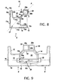
- the crow flap 10 may be such that the stiffening outer core 20 protrudes from the square outline defined by the main core 11 and the lateral branches 12, 13 (see FIG. figure 8 ). This allows in particular to improve the assembly of cabinets or neighboring cells, as illustrated figure 9 .
- the profiles E of neighboring cells are brought closer together until their abutment faces 20b ( figure 9 ). There remains then between the branches 13 of the two juxtaposed profiles a space for making or place an intermediate seal 30 without risk of crushing.
- a double seal is made vis-à-vis the outside, firstly by the abutment of the outer cores 20 and then by the interposition of the seal 30 between the branches 13, and inside the profiles are created.
- the assembly of the profiles E is completed by coupling parts 31 in the general U-shaped adapted to that of the housing 21.
- the parts 31 follow the shape of the outer sides 11c of the cores 11, the wings 14b of the central branches of the crow flaps and the inner sides 20c of the outer cores 20.
- the coupling parts 31 are tightened by bolts 32 inserted into threaded holes 17 of the sides 11c and accessible to tools through the orifices 16 formed in the opposite sides 11a.
- the trapezoidal housings 21 can serve to accommodate hinges 33 when it is desired to bring two doors D on adjacent sides of the square main core 11.
- the hinge 33 is housed in the rectangular portion of the rectangle trapezoid of the housing 21, via fixed screws in the holes 17, and the edge 34 of the door D, here folded at right angles, is housed in the triangular portion of the trapezium.
- the edge 35 of the wall is folded back to 180 ° to occupy most of the pentagonal space 21; the panel of the wall is connected to the return edge 35 by an oblique face in return 36 and the wall is assembled by means of drilled screws 37 and fixed in the tapped holes.
- the outer surface of the wall C may advantageously outcrop the side 20a (or 20b) of the outer core 20.
- the stiffening outer core 20 remains in the square outline, or below the square outline, defined by the main core 11 and the lateral branches 12,13 which extend the sides of this core.
- a fixed wall C or opening D can then cover by its panel a side 20a (or 20b) of the core 20 and a folded edge such as the edge 34 the other side 20b (or 20a) of the core.
Landscapes
- Engineering & Computer Science (AREA)
- Power Engineering (AREA)
- Casings For Electric Apparatus (AREA)
- Special Wing (AREA)
- Assembled Shelves (AREA)
- Blow-Moulding Or Thermoforming Of Plastics Or The Like (AREA)
- Iron Core Of Rotating Electric Machines (AREA)
- Organic Insulating Materials (AREA)
- Macromonomer-Based Addition Polymer (AREA)
- Furniture Connections (AREA)
- Hinges (AREA)
- Patch Boards (AREA)
Claims (10)
- Schrank für Elektrogeräte mit einem Gerüst, das durch Zusammenbau von Profilteilen geformt wird, wobei der Querschnitt zumindest bestimmter der Profilteile die Form eines Dreiecksverbands (10) hat, der einen inneren polygonalen Hauptkern (11) und drei Schenkel (12, 13, 14) aufweist, die an den Hauptkern anschließen,- die Schenkel des Dreiecksverbands (10) zur Außenseite des Schranks gerichtet sind,- die zwei Seitenschenkel (12, 13) im Wesentlichen lotrecht zueinander sind,- der Mittelschenkel (14) sich nach außen durch einen äußeren Versteifungskern (20) erweitert, dadurch gekennzeichnet, dass er geschlossen und hohl ist.
- Schrank nach Anspruch 1, dadurch gekennzeichnet, dass das Profilteil eine Symmetrieebene (P) aufweist, in der sich der Mittelschenkel (14) des Dreiecksverbands (10) befindet.
- Schrank nach Anspruch 2, dadurch gekennzeichnet, dass der Hauptkern (11) und der äußere Versteifungskern (20) gemäß der Symmetrieebene (P) fluchtend ausgerichtet sind.
- Schrank nach Anspruch 2 oder 3, dadurch gekennzeichnet, dass der Hauptkern (11) einen im Wesentlichen quadratischen Querschnitt hat, dessen Diagonale sich in der Symmetrieebene befindet.
- Schrank nach Anspruch 1, dadurch gekennzeichnet, dass der äußere Versteifungskern (20) einen im Wesentlichen quadratischen und kleineren Querschnitt hat als derjenige des Hauptkerns (11).
- Schrank nach Anspruch 1, dadurch gekennzeichnet, dass der Mittelschenkel (14) zwei Flügel (14a, 14b) aufweist, die aneinander grenzen.
- Schrank nach Anspruch 1, dadurch gekennzeichnet, dass die Seitenschenkel (12, 13) Flügel (12a, 12b, 13a, 13b) aufweisen, die voneinander getrennt sind, um nach außen ein Auflageflächenelement (12c, 13c) für eine feste oder sich öffnende Wand des Schranks zu bilden, und der äußere Versteifungskern (20) bezüglich der Flächenelemente nach außen auskragt, wobei die Auskragung (h) größer ist als die Dicke (e) der Wand.
- Schrank nach Anspruch 1, dadurch gekennzeichnet, dass der äußere Versteifungskern (20) zwischen sich und der gegenüberliegenden Seite (12b, 13b) jedes Seitenschenkels (12, 13) des Dreiecksverbands (10) einen im Wesentlichen trapezförmigen und über seine Basis nach außen offenen Sitz (21) bildet, wobei der Sitz ausgelegt ist, um Befestigungszubehörteile für feste oder sich öffnende Wände und der Ränder dieser Wände aufzunehmen.
- Schrank nach Anspruch 8, dadurch gekennzeichnet, dass die Wand einen um 180° umgeschlagenen Rand (35) aufweist, der sich in den im Wesentlichen trapezförmigen Sitz (23) einfügt.
- Schrank nach Anspruch 1, dadurch gekennzeichnet, dass die Seitenschenkel (12, 13) des Dreiecksverbands (10) leicht schräg und mit den jeweiligen Ecken des Hauptkerns (11) über einen Steifheitsabsatz (15) verbunden sind.
Applications Claiming Priority (2)
| Application Number | Priority Date | Filing Date | Title |
|---|---|---|---|
| FR0405771A FR2870995B1 (fr) | 2004-05-28 | 2004-05-28 | Armoire electrique a profiles d'ossature |
| FR0405771 | 2004-05-28 |
Publications (3)
| Publication Number | Publication Date |
|---|---|
| EP1601074A1 EP1601074A1 (de) | 2005-11-30 |
| EP1601074B1 EP1601074B1 (de) | 2007-04-11 |
| EP1601074B9 true EP1601074B9 (de) | 2008-07-23 |
Family
ID=34939817
Family Applications (1)
| Application Number | Title | Priority Date | Filing Date |
|---|---|---|---|
| EP05103996A Active EP1601074B9 (de) | 2004-05-28 | 2005-05-12 | Schaltschrank mit Rahmenprofilen |
Country Status (8)
| Country | Link |
|---|---|
| EP (1) | EP1601074B9 (de) |
| CN (1) | CN100578879C (de) |
| AT (1) | ATE359613T1 (de) |
| DE (1) | DE602005000850T2 (de) |
| DK (1) | DK1601074T3 (de) |
| ES (1) | ES2284126T3 (de) |
| FR (1) | FR2870995B1 (de) |
| PT (1) | PT1601074E (de) |
Families Citing this family (12)
| Publication number | Priority date | Publication date | Assignee | Title |
|---|---|---|---|---|
| DE102014100417B3 (de) * | 2014-01-15 | 2015-04-02 | Rittal Gmbh & Co. Kg | Rahmenprofil für ein Rahmengestell eines Schaltschranks sowie Befestigungsclip für das Rahmenprofil |
| DE102014101401A1 (de) | 2014-02-05 | 2015-08-06 | Rittal Gmbh & Co. Kg | Anreih-Schaltschranksystem |
| DE102014101402B4 (de) | 2014-02-05 | 2024-10-17 | Rittal Gmbh & Co. Kg | Rahmenprofil für ein Rahmengestell eines Schaltschrankes |
| DE102014102465B4 (de) | 2014-02-25 | 2022-08-18 | Rittal Gmbh & Co. Kg | Schaltschrank |
| TWI565395B (zh) * | 2015-01-16 | 2017-01-01 | 佳世達科技股份有限公司 | 框架組合 |
| DE102016124078B3 (de) * | 2016-12-12 | 2018-05-09 | Rittal Gmbh & Co. Kg | Verbindungsanordnung für die Verbindung von zwei Schaltschrankrahmengestellen |
| CN107454793A (zh) * | 2017-06-15 | 2017-12-08 | 上海复珊精密制造有限公司 | 一种多功能箱体框架型材 |
| DE202018100613U1 (de) | 2018-02-05 | 2018-02-14 | Rittal Gmbh & Co. Kg | Anordnung mit zwei über einen Anreihverbinder miteinander verbundenen Schaltschrankrahmengestellen |
| CN109168278A (zh) * | 2018-09-25 | 2019-01-08 | 北京华夏蓝图科技有限公司 | 一种型材及机柜 |
| FR3097714B1 (fr) * | 2019-06-24 | 2023-02-10 | Schneider Electric Ind Sas | Armature pour une armoire électrique, armoire électrique comportant une telle armature |
| CN110649468B (zh) * | 2019-09-02 | 2023-07-25 | 东华大学 | 一种有两个支撑边的机柜型材及相应的机架 |
| CN113346354A (zh) * | 2021-06-08 | 2021-09-03 | 天津瑞能电气有限公司 | 一种电控柜型材、其制作方法及使用该型材的电控柜 |
Family Cites Families (6)
| Publication number | Priority date | Publication date | Assignee | Title |
|---|---|---|---|---|
| DE1753038U (de) * | 1954-07-14 | 1957-09-26 | Hans Georg Dr Fassbender | Fernsteuerung fuer objekttischbewegung bei mikroprojektoren. |
| DE1753038A1 (de) * | 1968-03-06 | 1971-07-15 | Elek Gmbh | Unter Verwendung von Kunststoffrahmenprofilen hergestelltes Schrankgehaeuse,insbesondere Schalt- oder Verteilerschrank |
| DE8107658U1 (de) * | 1981-03-17 | 1981-08-20 | Hans Knürr KG Mechanik für die Elektronik, 8000 München | Gehäuse, insbesondere für elektrische und/oder elektronische Schaltungen |
| ATE90999T1 (de) * | 1989-10-13 | 1993-07-15 | Chih Ching Liuo | Eckverbindungsstruktur fuer zerlegbare schraenke. |
| DE19853611C1 (de) * | 1998-11-20 | 2000-04-06 | Skeppner Hans | Schaltschrank |
| BR0202231A (pt) * | 2002-06-06 | 2004-04-27 | Melquisedec Francisquini | Aperfeiçoamento em perfil metálico para composição de estruturas para montagem de quadros elétricos |
-
2004
- 2004-05-28 FR FR0405771A patent/FR2870995B1/fr not_active Expired - Fee Related
-
2005
- 2005-05-12 EP EP05103996A patent/EP1601074B9/de active Active
- 2005-05-12 DK DK05103996T patent/DK1601074T3/da active
- 2005-05-12 ES ES05103996T patent/ES2284126T3/es active Active
- 2005-05-12 AT AT05103996T patent/ATE359613T1/de active
- 2005-05-12 PT PT05103996T patent/PT1601074E/pt unknown
- 2005-05-12 DE DE602005000850T patent/DE602005000850T2/de active Active
- 2005-05-25 CN CN200510073868A patent/CN100578879C/zh active Active
Also Published As
| Publication number | Publication date |
|---|---|
| ATE359613T1 (de) | 2007-05-15 |
| ES2284126T3 (es) | 2007-11-01 |
| DK1601074T3 (da) | 2007-08-20 |
| PT1601074E (pt) | 2007-06-28 |
| DE602005000850T2 (de) | 2007-12-20 |
| FR2870995A1 (fr) | 2005-12-02 |
| DE602005000850D1 (de) | 2007-05-24 |
| CN100578879C (zh) | 2010-01-06 |
| CN1702930A (zh) | 2005-11-30 |
| FR2870995B1 (fr) | 2006-09-01 |
| EP1601074B1 (de) | 2007-04-11 |
| EP1601074A1 (de) | 2005-11-30 |
Similar Documents
| Publication | Publication Date | Title |
|---|---|---|
| EP1601074B9 (de) | Schaltschrank mit Rahmenprofilen | |
| EP0649205B1 (de) | Schrank mit Eckverbindung und ein Schaltschrank mit solchen Verbindungen | |
| FR2683956A1 (fr) | Chassis-cadre pour une armoire electrique. | |
| FR2800779A1 (fr) | Poteau support pour cloture | |
| FR3032003A1 (fr) | Poteau pour la realisation de fermeture tel que cloture, portail, porte ou similaire, ensemble et fermeture comprenant un tel poteau | |
| WO2017097433A1 (fr) | Élément de verrière démontable et procédé de montage | |
| EP0828053A2 (de) | Wärmedämmender Trennprofilkörper zum Einsetzen zwischen Aluminiumprofilen zur Verwendung bei der Herstellung von Türen und Fenster | |
| FR3037094A1 (fr) | Chassis de dormant et/ou d'ouvrant | |
| EP0014123A2 (de) | Verfahren und Vorrichtung zum miteinander Verbinden von Kanalteilstücken mit Fluidumzug | |
| FR3003290A1 (fr) | Encadrement destine a fixer sur un mur, le dormant d'un ouvrant, tel qu'une fenetre, une porte, une porte-fenetre. | |
| EP0651122A1 (de) | Verbesserung an Scharnieren zur gelenkigen Verbindung eines Flügels an einem Rahmen | |
| EP3299565A1 (de) | Verglasungsstruktur mit einem eckverbinder | |
| EP1050637B1 (de) | Trennwand, insbesondere Bürotrennwand | |
| FR3075245A1 (fr) | Agencement d'une porte a panneau, coupe-feu, avec inserts de fixation et de centrage | |
| FR2896632A1 (fr) | Armature d'armoire pour appareils electriques comportant des traverses et des montants relies par un profile d'emboitement | |
| EP1201869A1 (de) | Kunststoffflügel, sowie sein Herstellungsverfahren und zweiflügelige Öffnung, z.B. für ein Fenster | |
| FR2967442A1 (fr) | Huisserie pour porte ou fenetre composee de deux plaques de platre | |
| EP2049351A1 (de) | Kraftfahrzeugtürblatt mit einem versteifungselement und mit einem solchen türblatt ausgestattetes fahrzeug | |
| FR2898628A1 (fr) | Ensemble de fixation pour vantail comprenant au moins une patte d'articulation et une patte de fixation independantes l'une de l'autre | |
| FR3013376A1 (fr) | Dispositif de fixation d'un element de serrure | |
| FR2792026A1 (fr) | Elements d'assemblage de profiles pour panneaux | |
| EP3771799A1 (de) | Rahmen im kostengünstigen set für festen, drehbaren oder schiebe-öffnungsflügel eines tors | |
| FR2981679A1 (fr) | Huisserie metallique a caractere universel | |
| FR2789112A1 (fr) | Huisserie metallique realisee par assemblage par fente et languette de deux montants et un linteau | |
| FR2648497A1 (fr) | Element de panneau modulaire pour la construction, par assemblage, de locaux prefabriques, notamment pour installations sanitaires |
Legal Events
| Date | Code | Title | Description |
|---|---|---|---|
| PUAI | Public reference made under article 153(3) epc to a published international application that has entered the european phase |
Free format text: ORIGINAL CODE: 0009012 |
|
| AK | Designated contracting states |
Kind code of ref document: A1 Designated state(s): AT BE BG CH CY CZ DE DK EE ES FI FR GB GR HU IE IS IT LI LT LU MC NL PL PT RO SE SI SK TR |
|
| AX | Request for extension of the european patent |
Extension state: AL BA HR LV MK YU |
|
| 17P | Request for examination filed |
Effective date: 20051214 |
|
| AKX | Designation fees paid |
Designated state(s): AT BE BG CH CY CZ DE DK EE ES FI FR GB GR HU IE IS IT LI LT LU MC NL PL PT RO SE SI SK TR |
|
| GRAP | Despatch of communication of intention to grant a patent |
Free format text: ORIGINAL CODE: EPIDOSNIGR1 |
|
| GRAS | Grant fee paid |
Free format text: ORIGINAL CODE: EPIDOSNIGR3 |
|
| GRAA | (expected) grant |
Free format text: ORIGINAL CODE: 0009210 |
|
| AK | Designated contracting states |
Kind code of ref document: B1 Designated state(s): AT BE BG CH CY CZ DE DK EE ES FI FR GB GR HU IE IS IT LI LT LU MC NL PL PT RO SE SI SK TR |
|
| PG25 | Lapsed in a contracting state [announced via postgrant information from national office to epo] |
Ref country code: FI Free format text: LAPSE BECAUSE OF FAILURE TO SUBMIT A TRANSLATION OF THE DESCRIPTION OR TO PAY THE FEE WITHIN THE PRESCRIBED TIME-LIMIT Effective date: 20070411 Ref country code: SI Free format text: LAPSE BECAUSE OF FAILURE TO SUBMIT A TRANSLATION OF THE DESCRIPTION OR TO PAY THE FEE WITHIN THE PRESCRIBED TIME-LIMIT Effective date: 20070411 |
|
| REG | Reference to a national code |
Ref country code: GB Ref legal event code: FG4D Free format text: NOT ENGLISH |
|
| REG | Reference to a national code |
Ref country code: CH Ref legal event code: EP |
|
| REG | Reference to a national code |
Ref country code: IE Ref legal event code: FG4D Free format text: LANGUAGE OF EP DOCUMENT: FRENCH |
|
| REF | Corresponds to: |
Ref document number: 602005000850 Country of ref document: DE Date of ref document: 20070524 Kind code of ref document: P |
|
| REG | Reference to a national code |
Ref country code: PT Ref legal event code: SC4A Free format text: AVAILABILITY OF NATIONAL TRANSLATION Effective date: 20070619 |
|
| REG | Reference to a national code |
Ref country code: SE Ref legal event code: TRGR |
|
| GBT | Gb: translation of ep patent filed (gb section 77(6)(a)/1977) |
Effective date: 20070712 |
|
| PG25 | Lapsed in a contracting state [announced via postgrant information from national office to epo] |
Ref country code: IS Free format text: LAPSE BECAUSE OF FAILURE TO SUBMIT A TRANSLATION OF THE DESCRIPTION OR TO PAY THE FEE WITHIN THE PRESCRIBED TIME-LIMIT Effective date: 20070811 |
|
| REG | Reference to a national code |
Ref country code: DK Ref legal event code: T3 |
|
| REG | Reference to a national code |
Ref country code: ES Ref legal event code: FG2A Ref document number: 2284126 Country of ref document: ES Kind code of ref document: T3 |
|
| PG25 | Lapsed in a contracting state [announced via postgrant information from national office to epo] |
Ref country code: PL Free format text: LAPSE BECAUSE OF FAILURE TO SUBMIT A TRANSLATION OF THE DESCRIPTION OR TO PAY THE FEE WITHIN THE PRESCRIBED TIME-LIMIT Effective date: 20070411 |
|
| REG | Reference to a national code |
Ref country code: IE Ref legal event code: FD4D |
|
| PG25 | Lapsed in a contracting state [announced via postgrant information from national office to epo] |
Ref country code: CZ Free format text: LAPSE BECAUSE OF FAILURE TO SUBMIT A TRANSLATION OF THE DESCRIPTION OR TO PAY THE FEE WITHIN THE PRESCRIBED TIME-LIMIT Effective date: 20070411 Ref country code: IE Free format text: LAPSE BECAUSE OF FAILURE TO SUBMIT A TRANSLATION OF THE DESCRIPTION OR TO PAY THE FEE WITHIN THE PRESCRIBED TIME-LIMIT Effective date: 20070411 Ref country code: MC Free format text: LAPSE BECAUSE OF NON-PAYMENT OF DUE FEES Effective date: 20070531 Ref country code: BG Free format text: LAPSE BECAUSE OF FAILURE TO SUBMIT A TRANSLATION OF THE DESCRIPTION OR TO PAY THE FEE WITHIN THE PRESCRIBED TIME-LIMIT Effective date: 20070711 |
|
| PLBE | No opposition filed within time limit |
Free format text: ORIGINAL CODE: 0009261 |
|
| STAA | Information on the status of an ep patent application or granted ep patent |
Free format text: STATUS: NO OPPOSITION FILED WITHIN TIME LIMIT |
|
| PG25 | Lapsed in a contracting state [announced via postgrant information from national office to epo] |
Ref country code: SK Free format text: LAPSE BECAUSE OF FAILURE TO SUBMIT A TRANSLATION OF THE DESCRIPTION OR TO PAY THE FEE WITHIN THE PRESCRIBED TIME-LIMIT Effective date: 20070411 Ref country code: LT Free format text: LAPSE BECAUSE OF FAILURE TO SUBMIT A TRANSLATION OF THE DESCRIPTION OR TO PAY THE FEE WITHIN THE PRESCRIBED TIME-LIMIT Effective date: 20070411 |
|
| 26N | No opposition filed |
Effective date: 20080114 |
|
| PG25 | Lapsed in a contracting state [announced via postgrant information from national office to epo] |
Ref country code: GR Free format text: LAPSE BECAUSE OF FAILURE TO SUBMIT A TRANSLATION OF THE DESCRIPTION OR TO PAY THE FEE WITHIN THE PRESCRIBED TIME-LIMIT Effective date: 20070712 |
|
| PG25 | Lapsed in a contracting state [announced via postgrant information from national office to epo] |
Ref country code: RO Free format text: LAPSE BECAUSE OF FAILURE TO SUBMIT A TRANSLATION OF THE DESCRIPTION OR TO PAY THE FEE WITHIN THE PRESCRIBED TIME-LIMIT Effective date: 20070411 |
|
| PG25 | Lapsed in a contracting state [announced via postgrant information from national office to epo] |
Ref country code: EE Free format text: LAPSE BECAUSE OF FAILURE TO SUBMIT A TRANSLATION OF THE DESCRIPTION OR TO PAY THE FEE WITHIN THE PRESCRIBED TIME-LIMIT Effective date: 20070411 |
|
| PG25 | Lapsed in a contracting state [announced via postgrant information from national office to epo] |
Ref country code: CY Free format text: LAPSE BECAUSE OF FAILURE TO SUBMIT A TRANSLATION OF THE DESCRIPTION OR TO PAY THE FEE WITHIN THE PRESCRIBED TIME-LIMIT Effective date: 20070411 |
|
| PG25 | Lapsed in a contracting state [announced via postgrant information from national office to epo] |
Ref country code: LU Free format text: LAPSE BECAUSE OF NON-PAYMENT OF DUE FEES Effective date: 20070512 |
|
| PG25 | Lapsed in a contracting state [announced via postgrant information from national office to epo] |
Ref country code: TR Free format text: LAPSE BECAUSE OF FAILURE TO SUBMIT A TRANSLATION OF THE DESCRIPTION OR TO PAY THE FEE WITHIN THE PRESCRIBED TIME-LIMIT Effective date: 20070411 Ref country code: HU Free format text: LAPSE BECAUSE OF FAILURE TO SUBMIT A TRANSLATION OF THE DESCRIPTION OR TO PAY THE FEE WITHIN THE PRESCRIBED TIME-LIMIT Effective date: 20071012 |
|
| REG | Reference to a national code |
Ref country code: CH Ref legal event code: PL |
|
| PG25 | Lapsed in a contracting state [announced via postgrant information from national office to epo] |
Ref country code: LI Free format text: LAPSE BECAUSE OF NON-PAYMENT OF DUE FEES Effective date: 20090531 Ref country code: CH Free format text: LAPSE BECAUSE OF NON-PAYMENT OF DUE FEES Effective date: 20090531 |
|
| REG | Reference to a national code |
Ref country code: DE Ref legal event code: R082 Ref document number: 602005000850 Country of ref document: DE Representative=s name: MANITZ, FINSTERWALD & PARTNER GBR, DE |
|
| REG | Reference to a national code |
Ref country code: DE Ref legal event code: R082 Ref document number: 602005000850 Country of ref document: DE Representative=s name: MANITZ FINSTERWALD PATENTANWAELTE PARTMBB, DE Effective date: 20141209 Ref country code: DE Ref legal event code: R081 Ref document number: 602005000850 Country of ref document: DE Owner name: SCHNEIDER ELECTRIC INDUSTRIES SAS, FR Free format text: FORMER OWNER: SCHNEIDER ELECTRIC ESPANA, S.A., BARCELONA, ES Effective date: 20141209 Ref country code: DE Ref legal event code: R081 Ref document number: 602005000850 Country of ref document: DE Owner name: SCHNEIDER ELECTRIC INDUSTRIES SAS, FR Free format text: FORMER OWNER: HISPANO MECANO ELECTRICA S.A., CAPELLADES, (BARCELONA), ES Effective date: 20141209 Ref country code: DE Ref legal event code: R082 Ref document number: 602005000850 Country of ref document: DE Representative=s name: MANITZ, FINSTERWALD & PARTNER GBR, DE Effective date: 20141209 |
|
| REG | Reference to a national code |
Ref country code: ES Ref legal event code: PC2A Owner name: SCHNEIDER ELECTRIC INDUSTRIES SAS Effective date: 20150122 Ref country code: GB Ref legal event code: 732E Free format text: REGISTERED BETWEEN 20150105 AND 20150107 |
|
| REG | Reference to a national code |
Ref country code: FR Ref legal event code: TP Owner name: SCHNEIDER ELECTRIC INDUSTRIES SAS, FR Effective date: 20150108 |
|
| REG | Reference to a national code |
Ref country code: FR Ref legal event code: PLFP Year of fee payment: 12 |
|
| REG | Reference to a national code |
Ref country code: FR Ref legal event code: PLFP Year of fee payment: 13 |
|
| REG | Reference to a national code |
Ref country code: FR Ref legal event code: PLFP Year of fee payment: 14 |
|
| PGFP | Annual fee paid to national office [announced via postgrant information from national office to epo] |
Ref country code: NL Payment date: 20240527 Year of fee payment: 20 |
|
| PGFP | Annual fee paid to national office [announced via postgrant information from national office to epo] |
Ref country code: GB Payment date: 20240521 Year of fee payment: 20 |
|
| PGFP | Annual fee paid to national office [announced via postgrant information from national office to epo] |
Ref country code: DE Payment date: 20240529 Year of fee payment: 20 |
|
| PGFP | Annual fee paid to national office [announced via postgrant information from national office to epo] |
Ref country code: DK Payment date: 20240527 Year of fee payment: 20 |
|
| PGFP | Annual fee paid to national office [announced via postgrant information from national office to epo] |
Ref country code: ES Payment date: 20240610 Year of fee payment: 20 |
|
| PGFP | Annual fee paid to national office [announced via postgrant information from national office to epo] |
Ref country code: AT Payment date: 20240521 Year of fee payment: 20 |
|
| PGFP | Annual fee paid to national office [announced via postgrant information from national office to epo] |
Ref country code: FR Payment date: 20240527 Year of fee payment: 20 |
|
| PGFP | Annual fee paid to national office [announced via postgrant information from national office to epo] |
Ref country code: PT Payment date: 20240429 Year of fee payment: 20 |
|
| PGFP | Annual fee paid to national office [announced via postgrant information from national office to epo] |
Ref country code: SE Payment date: 20240527 Year of fee payment: 20 Ref country code: BE Payment date: 20240527 Year of fee payment: 20 |
|
| PGFP | Annual fee paid to national office [announced via postgrant information from national office to epo] |
Ref country code: IT Payment date: 20240524 Year of fee payment: 20 |