EP1564786B1 - Beleuchtungsvorrichtung - Google Patents
Beleuchtungsvorrichtung Download PDFInfo
- Publication number
- EP1564786B1 EP1564786B1 EP05001257A EP05001257A EP1564786B1 EP 1564786 B1 EP1564786 B1 EP 1564786B1 EP 05001257 A EP05001257 A EP 05001257A EP 05001257 A EP05001257 A EP 05001257A EP 1564786 B1 EP1564786 B1 EP 1564786B1
- Authority
- EP
- European Patent Office
- Prior art keywords
- discharge
- illumination device
- electrical
- lamp
- red
- Prior art date
- Legal status (The legal status is an assumption and is not a legal conclusion. Google has not performed a legal analysis and makes no representation as to the accuracy of the status listed.)
- Expired - Lifetime
Links
- 239000003086 colorant Substances 0.000 claims abstract description 6
- 229910052724 xenon Inorganic materials 0.000 claims abstract description 6
- FHNFHKCVQCLJFQ-UHFFFAOYSA-N xenon atom Chemical compound [Xe] FHNFHKCVQCLJFQ-UHFFFAOYSA-N 0.000 claims abstract description 6
- 238000000576 coating method Methods 0.000 claims description 36
- OAICVXFJPJFONN-UHFFFAOYSA-N Phosphorus Chemical compound [P] OAICVXFJPJFONN-UHFFFAOYSA-N 0.000 claims description 35
- 238000005286 illumination Methods 0.000 claims description 35
- 239000011248 coating agent Substances 0.000 claims description 34
- 230000005855 radiation Effects 0.000 claims description 14
- QSHDDOUJBYECFT-UHFFFAOYSA-N mercury Chemical compound [Hg] QSHDDOUJBYECFT-UHFFFAOYSA-N 0.000 claims description 8
- 229910052753 mercury Inorganic materials 0.000 claims description 8
- 229920006395 saturated elastomer Polymers 0.000 claims description 8
- 238000001228 spectrum Methods 0.000 claims description 6
- 229910052754 neon Inorganic materials 0.000 claims description 5
- GKAOGPIIYCISHV-UHFFFAOYSA-N neon atom Chemical compound [Ne] GKAOGPIIYCISHV-UHFFFAOYSA-N 0.000 claims description 5
- 230000004888 barrier function Effects 0.000 claims 4
- 239000007858 starting material Substances 0.000 abstract 1
- DXNVUKXMTZHOTP-UHFFFAOYSA-N dialuminum;dimagnesium;barium(2+);oxygen(2-) Chemical compound [O-2].[O-2].[O-2].[O-2].[O-2].[O-2].[O-2].[Mg+2].[Mg+2].[Al+3].[Al+3].[Ba+2].[Ba+2] DXNVUKXMTZHOTP-UHFFFAOYSA-N 0.000 description 3
- 229910052736 halogen Inorganic materials 0.000 description 3
- 150000002367 halogens Chemical class 0.000 description 3
- 239000000203 mixture Substances 0.000 description 2
- 230000003595 spectral effect Effects 0.000 description 2
- 229910052684 Cerium Inorganic materials 0.000 description 1
- 229910052771 Terbium Inorganic materials 0.000 description 1
- 235000019642 color hue Nutrition 0.000 description 1
- 230000007423 decrease Effects 0.000 description 1
- 230000001419 dependent effect Effects 0.000 description 1
- LQFNMFDUAPEJRY-UHFFFAOYSA-K lanthanum(3+);phosphate Chemical compound [La+3].[O-]P([O-])([O-])=O LQFNMFDUAPEJRY-UHFFFAOYSA-K 0.000 description 1
- RUDFQVOCFDJEEF-UHFFFAOYSA-N oxygen(2-);yttrium(3+) Chemical compound [O-2].[O-2].[O-2].[Y+3].[Y+3] RUDFQVOCFDJEEF-UHFFFAOYSA-N 0.000 description 1
- 230000000630 rising effect Effects 0.000 description 1
- 230000035807 sensation Effects 0.000 description 1
- 235000019615 sensations Nutrition 0.000 description 1
Images



Classifications
-
- H—ELECTRICITY
- H01—ELECTRIC ELEMENTS
- H01J—ELECTRIC DISCHARGE TUBES OR DISCHARGE LAMPS
- H01J61/00—Gas-discharge or vapour-discharge lamps
- H01J61/02—Details
- H01J61/30—Vessels; Containers
-
- H—ELECTRICITY
- H01—ELECTRIC ELEMENTS
- H01J—ELECTRIC DISCHARGE TUBES OR DISCHARGE LAMPS
- H01J65/00—Lamps without any electrode inside the vessel; Lamps with at least one main electrode outside the vessel
- H01J65/04—Lamps in which a gas filling is excited to luminesce by an external electromagnetic field or by external corpuscular radiation, e.g. for indicating plasma display panels
- H01J65/042—Lamps in which a gas filling is excited to luminesce by an external electromagnetic field or by external corpuscular radiation, e.g. for indicating plasma display panels by an external electromagnetic field
- H01J65/046—Lamps in which a gas filling is excited to luminesce by an external electromagnetic field or by external corpuscular radiation, e.g. for indicating plasma display panels by an external electromagnetic field the field being produced by using capacitive means around the vessel
-
- H—ELECTRICITY
- H01—ELECTRIC ELEMENTS
- H01J—ELECTRIC DISCHARGE TUBES OR DISCHARGE LAMPS
- H01J61/00—Gas-discharge or vapour-discharge lamps
- H01J61/02—Details
- H01J61/30—Vessels; Containers
- H01J61/32—Special longitudinal shape, e.g. for advertising purposes
- H01J61/327—"Compact"-lamps, i.e. lamps having a folded discharge path
-
- H—ELECTRICITY
- H01—ELECTRIC ELEMENTS
- H01J—ELECTRIC DISCHARGE TUBES OR DISCHARGE LAMPS
- H01J61/00—Gas-discharge or vapour-discharge lamps
- H01J61/92—Lamps with more than one main discharge path
-
- H—ELECTRICITY
- H01—ELECTRIC ELEMENTS
- H01J—ELECTRIC DISCHARGE TUBES OR DISCHARGE LAMPS
- H01J61/00—Gas-discharge or vapour-discharge lamps
- H01J61/02—Details
- H01J61/12—Selection of substances for gas fillings; Specified operating pressure or temperature
- H01J61/16—Selection of substances for gas fillings; Specified operating pressure or temperature having helium, argon, neon, krypton, or xenon as the principle constituent
Definitions
- the invention is based on an electric lighting device for producing saturated colors with at least two lighting units, the lighting units each having a discharge vessel with a low-pressure discharge and a phosphor coating on the inner wall of the vessel.
- FIG. 1 the color locus of an incandescent lamp is shown in undimmed state (location 1) and in dimmed state (location 2).
- location 1 the color temperature decreases simultaneously with the illuminance, the light becomes "warmer", the proportion of light emitted in the red spectral range increases.
- the incandescent lamp thus shows a similar behavior as the daylight, which has a lower illuminance in the morning and evening as well as a lower color temperature than at noon.
- the human eye and sensation are adjusted to it. That the color temperature of Hg fluorescent lamps remains constant when dimming or even rising, however, is perceived as unpleasant.
- the object of the invention is therefore to provide a lighting device which circumvents the disadvantages listed above.
- the object is in the electric lighting device for producing saturated colors with at least two lighting units, wherein the lighting units each have a discharge vessel with a low-pressure discharge and a phosphor coating on the inner wall of the vessel have, solved in that at least one lighting unit has a discharge vessel with a low-pressure mercury discharge and at least one Beleutungsappel a discharge vessel with a xenon filling and a dielectrically impeded discharge (Xe excimer discharge).
- the lamp combination contains red and green Xe excimer fluorescent lamps, the color triangle widens into the green, yellow and red color range. Thus saturated red and yellow light colors can be reached and thus the color temperatures of a dimmed incandescent lamp can be set.
- the Xe excimer lamp can also use other VUV excitable phosphors, such as alternative Tb-doped green phosphors and Eu-doped red phosphors whose emission radiation has a color location close to the spectral color. Suitable phosphors are for example in the WO94 / 22975 listed. In the case of the Xe excimer lamps, the color locus of the lamp corresponds to that of the phosphor applied, since the dielectrically impeded Xe discharge itself contributes practically no visible radiation component.
- the color locus of the lamp does not coincide with the color locus of the phosphor applied, since the Hg discharge has its own color locus in the visible (see Hgvis in FIG. 1 ) owns.
- the discharge vessel with the Xe excimer discharge advantageously has on the inner wall of the discharge vessel a phosphor coating for generating a red color spectrum.
- the second illumination unit can also have a discharge vessel with a Xe excimer discharge for this purpose, wherein the discharge vessel is a phosphor coating on the inner wall of the green spectrum generating vessel has:
- the color location for the blue portion of the color mixture differs very little from the color location obtained with a mercury discharge and the same phosphor coating when using a discharge vessel with an Xe excimer discharge and a phosphor coating in the form of barium magnesium aluminate: Eu, It is also conceivable to use a mercury fluorescent lamp as a lamp unit instead of a Xe excimer fluorescent lamp.
- Hg fluorescent lamps In addition to a combination of lighting units with Xe excimer fluorescent lamps and a red, green and blue phosphor coating, mixed unit combinations of Hg fluorescent lamps and Xe excimer fluorescent lamps are also suitable for general lighting. For example, to achieve high luminous efficiencies for blue and green, one could use Hg fluorescent lamps, for red either only a Xe excimer fluorescent lamp or a Xe excimer fluorescent lamp in addition to a red Hg fluorescent lamp. The lower light output of the red Xe excimer fluorescent lamp is then not significant, since its radiation component is needed exactly when the other lamps are dimmed.
- the Xe excimer lamps can have any shape; they can be designed, for example, as a line radiator with a circular cross section or as a surface radiator.
- the Hg low-pressure discharge lamps can be designed as flashlights with different sizes, circular diameter or as compact lamps with a multi-curved tube with a circular cross-section.
- the discharge vessels of the units may have an internal reflector to allow a directed emission of the radiation
- the discharge vessels of the individual units can be single-ended or double-ended.
- the discharge vessels of the individual lighting units can be controlled and dimmed by means of electronic ballasts. This ensures the setting of any color location in the color triangle.
- the entire lighting unit can be designed as a light. Since the radiation generated by the individual building units must be mixed due to the different color temperatures or colors, so that the viewer receives a spatially uniform color impression, it is necessary that the radiation in the lamp is diffused at least once diffused.
- the luminaire advantageously has a reflector and / or a diffuse cover.
- the lighting device as a compact low-pressure discharge lamp with a central base at one end, in which case the discharge vessels of the individual lighting units have to have the shape of a multiply bent pipe whose ends are brought together and fastened in the base.
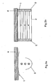
- FIGS. 2a and 2b schematically shows a lighting device, which does not belong to the claimed invention, in the form of a ceiling light with three lighting units in the form of interconnected rod-shaped discharge vessels with a Xe excimer discharge (Xe excimer lamp), wherein the uppermost, arranged near the ceiling 4 Xe Excimer lamp R is a red emitting phosphor coating, the middle Xe excimer lamp G has a green emitting phosphor coating, and the bottom Xe excimer lamp B has a blue emitting phosphor coating.
- Xe excimer lamp Xe excimer lamp
- Each located at the ends of the straight lamps socket are mounted in common sockets 5 and contacted.
- the associated ballasts for operating and dimming the Xe excimer lamps R, G, B are not shown here.
- the mixture of the radiation of these three lamps is effected by two curved reflectors, wherein a reflector 1 above the lamps are arranged on the ceiling 4 and a reflector 2 below the lamps in the lamp.
- FIG. 3 indicated lamp essentially corresponds to the light FIG. 2 ,
- the Xe excimer lamps R, G, B are not arranged one below the other but side by side.
- FIG. 4 shows another form of in FIG. 2 shown lamp, which does not belong to the claimed invention, wherein the Xe excimer lamps R, G, B - seen parallel to the ceiling 4 - are arranged in an equilateral triangle.
- FIGS. 5a and b is another lighting device, which does not belong to the claimed invention, shown in the form of a lamp.
- the luminaire here includes three lighting units in the form of U-shaped bent discharge vessels R, G, B, each with an Xe filling, a dielectrically impeded discharge and a red or green or blue emitting phosphor coating, wherein the discharge vessels in a common base Socket system 6 are merged.
- the ballasts for operation and for dimming the lighting units are housed in the base socket system 6.
- the discharge vessels are arranged rotationally symmetrical about an axis perpendicular to the ceiling 4 in the luminaire.
- the lamp has a reflector 1 at the top and a reflector 2 at the bottom of the lamp.
- FIG. 6 illustrated luminaire which does not belong to the claimed invention, substantially corresponds to in FIG. 3 shown light. However, instead of the reflector at the bottom, this lamp has a diffusing screen 3 for diffuse mixing of the radiation emitted by the lamps.
- FIG. 7 shows another variant of in FIG. 3 illustrated light.
- the Xe excimer lamps R, G, B provided with internal reflector coatings 7.
- the reflector coatings are arranged so that the radiation emitted by the lamps radiation experiences in cooperation with the reflector 1 at the top of the lamp to the ceiling 4 towards optimum mixing.
- FIG. 9 is another variant of the lamp too FIG. 6 listed.
- the three Xe excimer lamps here twelve Xe excimer lamps, each with a straight tubular discharge vessel and an alternately red R, green G and blue B radiation emitting phosphor coating are arranged parallel to the ceiling 4. This results in a surface light having a reflector 1 for mixing the radiation on the upper side and a diffuser 3 on the underside of the luminaire.
- FIG. 10 shown lamp largely corresponds to the light FIG. 4 , instead of the three Xe excimer lamps, however, a rod-shaped Xe excimer lamp R with a red-emitting phosphor coating and according to the invention a bar-shaped Hg low-pressure discharge lamp W with a red, green and blue or white emitting phosphor coating integrated in the lamp.
- FIG. 11 Similar to the in FIG. 8 indicated light is the in FIG. 11 illustrated lamp constructed. It has in the middle a rod-shaped Xe excimer lamp R with a red emitting phosphor coating and an internal reflector coating 7 and left and right of it a rod-shaped Hg low-pressure discharge lamp W without reflector coating with a white-emitting phosphor coating, wherein the discharge vessels each parallel to each other and run parallel to the ceiling 4.
- FIG. 12 The light in FIG. 12 is similar in structure to that FIG. 11 , wherein here in the middle of a rod-shaped Hg low-pressure discharge lamp W with a white emitting phosphor coating and left and right of a staggered rod-shaped Xe excimer lamp R are arranged with a red emitting phosphor coating and an internal reflector coating 7.
- FIG. 14 shows a sheet-like lamp in which the ceiling 4 towards first a sheet-like Xe excimer lamp R with a red emitting phosphor coating and then four rod-shaped Hg low-pressure discharge lamp W are integrated with a white emitting phosphor coating in the lamp.
- the lamp has a reflector 1 at the top and a diffuser 3 at the bottom.
- FIGS. 13a and b a lighting device according to the invention is shown in the form of a compact low-pressure discharge lamp.
- the lamp includes three lighting units in the form of U-shaped bent and arranged in an equilateral triangle discharge vessels W each having a low-pressure Hg discharge and a white-emitting phosphor coating, wherein the discharge vessels are brought together in a common base 6.
- a further lighting unit in the form of a tubular Xe excimer lamp R with a red emitting phosphor coating is arranged parallel to the axes of the longitudinal tubes of the U-shaped bent discharge vessels.
- the ballasts for operation and for dimming the lighting units are housed in the base 6.
- the base 6 has a screw thread of the type E27 at the end remote from the discharge vessels.
Landscapes
- Physics & Mathematics (AREA)
- Electromagnetism (AREA)
- Engineering & Computer Science (AREA)
- Plasma & Fusion (AREA)
- Non-Portable Lighting Devices Or Systems Thereof (AREA)
- Vessels And Coating Films For Discharge Lamps (AREA)
- Discharge-Lamp Control Circuits And Pulse- Feed Circuits (AREA)
- Vehicle Body Suspensions (AREA)
- Polarising Elements (AREA)
- Seal Device For Vehicle (AREA)
- Discharge Lamp (AREA)
Description
- Die Erfindung geht aus von einer elektrischen Beleuchtungsvorrichtung zur Erzeugung gesättigter Farben mit mindestens zwei Beleuchtungseinheiten, wobei die Beleuchtungseinheiten jeweils ein Entladungsgefäß mit einer Niederdruckentladung und einer Leuchtstoffbeschichtung auf der Innenwand des Gefäßes besitzen.
- Bisher gibt es keine Beleuchtungsvorrichtungen, die einerseits in ungedimmten Zustand weit höhere Lichtausbeuten als eine Glüh- oder Halogenglühlampe besitzen und anderseits eine Farbtemperatur besitzen, die sich beim Dimmen wie bei einer Glühlampe ändert.
- In
Figur 1 ist der Farbort einer Glühlampe in ungedimmten Zustand (Ort 1) und in gedimmten Zustand (Ort 2) aufgezeigt. Beim Dimmen der Glühlampe verringert sich gleichzeitig mit der Beleuchtungsstärke auch die Farbtemperatur, das Licht wird "wärmer", der Anteil des im roten Spektralbereich emittierten Lichtes wächst. Die Glühlampe zeigt damit ein ähnliches Verhalten wie das Tageslicht, das morgens und abends sowohl eine geringere Beleuchtungsstärke als auch eine niedrigere Farbtemperatur als mittags hat. Das menschliche Auge und Empfinden sind darauf eingestellt. Dass die Farbtemperatur von Hg-Leuchtstofflampen beim Dimmen konstant bleibt oder sogar ansteigt, wird dagegen als unangenehm empfunden. - Eine weiteres Problem ist, dass mit Beleuchtungsvorrichtungen, die mit Glüh- oder Halogenglühlampen bestückt sind, die Lichtfarbe nicht über einen möglichst großen Bereich des Farbdreiecks variiert werden kann. Glüh- oder Halogenglühlampen sind dafür nicht geeignet, weil ihre Lichtausbeute gering ist und ihr Farbort mehr oder weniger auf dem Plankschen Strahlenzug liegt (
Figur 1 ). Der Rest des Farbdreiecks kann nur mit Hilfe von Farbfiltern erreicht werden, die die Lichtausbeute verringern würden. - Als eine Lösung wird diskutiert, mehrere Hg-Leuchtstofflampen zu kombinieren. Mit einer Leuchtstofflampe mit einer Quecksilberentladung, einer blauen (Bariummagnesiumaluminat:Eu = Hg-BAM), einer grünen (Cermagnesiumaluminat:Tb = Hg-CAT) und einer roten (Yttriumoxid:Eu =YOE) Leuchtstoffbeschichtung sowie einem gemeinsamen EVG, welches die Intensitäten der drei Leuchtstofflampen unabhängig voneinander variieren kann, können alle Farbörter im von den drei einzelnen Leuchtstofflampen aufgespannten Farbdreieck (Hg-BAM, Hg-CAT, Hg-YOE) eingestellt werden (siehe
Figur 1 ). Der Nachteil dieser Lösung ist aber, dass mit Hg-Leuchtstofflampen kein gesättigt rotes, grünes oder gelbes Licht erzeugt werden kann, weil die Hg-Niederdruckentladung neben der den Leuchtstoff anregenden UV-Strahlung einen zu großen Anteil blaues Licht emittiert. Damit kann auch weißes Licht mit Farbtemperaturen < 2600 K nicht erzeugt werden, wie es z.B. beim Dimmen einer Glühlampe erzeugt wird. - Aufgabe der Erfindung ist es daher eine Beleuchtungsvorrichtung zu schaffen, die die oben aufgeführten Nachteile umgeht.
- Die Aufgabe wird bei der elektrische Beleuchtungsvorrichtung zur Erzeugung gesättigter Farben mit mindestens zwei Beleuchtungseinheiten, wobei die Beleuchtungseinheiten jeweils ein Entladungsgefäß mit einer Niederdruckentladung und einer Leuchtstoffbeschichtung auf der Innenwand des Gefäßes besitzen, dadurch gelöst, dass mindestens eine Beleuchtungseinheit ein Entladungsgefäß mit einer Quecksilber-Niederdruckentladung und mindestens eine Beleutungseinheit ein Entladungsgefäß mit einer Xenon-Füllung und einer dielektrisch behinderten Entladung (Xe-Exzimer-Entladung) aufweist.
-
Figur 1 zeigt die Farbdreiecke, die durch die Kombination je einer Hg-Leuchtstofflampe mit einer roten, grünen und blauen (Hg-YOE, Hg-CAT, Hg-BAM) Leuchtstoffbeschichtung bzw. einer Xe-Exzimer-Leuchtstofflampe mit einer roten (Yttriumgadoliniumborat:Eu = XeYOB), grünen (Lanthanphosphat:Ce, Tb = Xe-LAP) und blauen (Bariummagnesiumaluminat:Eu = Xe-BAM) Leuchtstoffbeschichtung aufgespannt werden. Beinhaltet die Lampenkombination rote und grüne Xe-Exzimer-Leuchtstofflampen, so erweitert sich das Farbdreieck in den grünen, gelben und roten Farbbereich. Es sind somit auch gesättigt rote und gelbe Lichtfarben erreichbar und damit die Farbtemperaturen einer gedimmten Glühlampe einstellbar. - Anstelle der Leuchtstoffe BAM, LAP und YOB können bei der Xe-Exzimer-Lampe auch andere VUV-anregbare Leuchtstoffe, wie alternative Tb-dotierte Grünleuchtstoffe und Eu-dotierte Rotleuchtstoffe verwendet werden, deren Emissionsstrahlung einen Farbort nahe dem Spektralfarbenzug haben. Geeignete Leuchtstoffe sind z.B. in der
WO94/22975 Figur 1 ) besitzt. - Das Entladungsgefäß mit der Xe-Exzimer-Entladung weist dafür vorteilhaft auf der Innenwand des Entladungsgefäßes eine Leuchtstoffbeschichtung zur Erzeugung eines roten Farbspektrums auf. Außerdem kann dazu auch die zweite Beleuchtungseinheit ein Entladungsgefäß mit einer Xe-Exzimer-Entladung aufweisen, wobei das Entladungsgefäß eine Leuchtstoffbeschichtung auf der Innenwand des Gefäßes zur Erzeugung eines grünen Spektrums besitzt:
- Da der Farbort für den blauen Anteil der Farbmischung sich bei Verwendung eines Entladungsgefäßes mit einer Xe-Exzimer-Entladung und einer Leuchtstoffbeschichtung in Form eines Bariummagnesiumaluminat:Eu nur sehr wenig von dem Farbort unterscheidet, der mit einer Quecksilber-Entladung und derselben Leuchtstoffbeschichtung erzielt wird, ist es auch denkbar, hier als Lampeneinheit anstelle einer Xe-Exzimer-Leuchtstofflampe eine Quecksilber-Leuchtstofflampe zu verwenden.
- Neben einer Kombination alleine aus Beleuchtungseinheiten mit Xe-Exzimer-Leuchtstofflampen und einer roten, grünen und blauen Leuchtstoffbeschichtung sind für die Allgemeinbeleuchtung auch gemischte Baueinheiten-Kombinationen aus Hg-Leuchtstofflampen und Xe-Exzimer-Leuchtstofflampen geeignet. Zum Beispiel könnte man zur Erzielung hoher Lichtausbeuten für Blau und Grün Hg-Leuchtstofflampen verwenden, für Rot entweder nur eine Xe-Exzimer-Leuchtstofflampe oder eine Xe-Exzimer-Leuchtstofflampe zusätzlich zu einer roten Hg-Leuchtstofflampe. Die geringere Lichtausbeute der roten Xe-Exzimer-Leuchtstofflampe fällt dann nicht ins Gewicht, da ihr Strahlungsanteil genau dann benötigt wird, wenn die anderen Lampen gedimmt werden.
- Hier ist auch die zusätzliche Verwendung einer Niederdruckentladungslampe ohne Quecksilber mit einer reinen Neonfüllung denkbar. Bei der Neon-Lampe werden die Resonanzlinien des Neon, die im Roten liegen, angeregt. Dadurch lässt sich ein gesättigtes Rot erreichen, ohne dass ein Leuchtstoff benutzt werden muss. Die Neon-Lampe hat eine lange Lebensdauer und ist dimmbar, was eine notwendige Voraussetzung für die leistungsabhängige Kombination mit den anderen Baueinheiten darstellt.
- Die Xe-Exzimerlampen können beliebige Form haben; sie können zum Beispiel als Linienstrahler mit einem kreisförmigen Querschnitt oder als Flächenstrahler ausgeführt sein. Die Hg-Niederdruckentladungslampen können als Stablampen mit unterschiedlich großem, kreisförmigen Durchmesser oder auch als Kompaktlampen mit einem mehrfach gebogenen Rohr mit kreisförmigem Querschnitt ausgeführt sein.
- Vorteilhaft können die Entladungsgefäße der Baueinheiten einen internen Reflektor besitzen um eine gerichtete Emission der Strahlung zu ermöglichen
- Die Entladungsgefäße der einzelnen Baueinheiten können einseitig oder zweiseitig gesockelt ein.
- Die Entladungsgefäße der einzelnen Beleuchtungseinheiten können mittels elektronischer Vorschaltgeräte angesteuert und gedimmt werden. Dadurch ist die Einstellung eines beliebigen Farbort im Farbdreieck gewährleistet.
- Die gesamte Beleuchtungseinheit kann als Leuchte ausgeführt sein. Da die von den einzelnen Baueinheiten erzeugte Strahlung aufgrund der verschieden Farbtemperaturen bzw. Farbörter gemischt werden muss, damit der Betrachter einen räumlich gleichmäßigen Farbeindruck erhält, ist es erforderlich dass die Strahlung in der Leuchte zumindest einmal diffus gestreut wird. Die Leuchte weist dazu vorteilhaft einen Reflektor und /oder eine diffuse Abdeckung auf.
- Es ist aber auch denkbar die Beleuchtungsvorrichtung als kompakte Niederdruckentladungslampe mit einem zentralen Sockel an einem Ende auszuführen, wobei dann die Entladungsgefäße der einzelnen Beleuchtungseinheiten die Gestalt eines mehrfach gebogenen Rohres besitzen müssen, dessen Enden in dem Sockel zusammengeführt und befestigt sind.
- Im folgenden wird die Erfindung beispielhaft anhand der folgenden Ausführungsbeispiele beschrieben:
- Figur 1
- zeigt Farbdreiecke für Xe-Exzimer-Lampen und Hg-Niederdruckentladungslampen mit einer roten, grünen und blauen Leuchtstoffbeschichtung
- Figur 2a, b
- zeigt schematisch ein nicht zur Erfindung gehörendes Beispiel einer Beleuchtungsvorrichtung in Form einer Leuchte in Seitenansicht
- Figur 3
- zeigt schematisch ein zweites nicht zur Erfindung gehörendes Beispiel einer Beleuchtungsvorrichtung in Form einer Leuchte
- Figur 4
- zeigt schematisch ein drittes nicht zur Erfindung gehörendes Beispiel einer Beleuchtungsvorrichtung in Form einer Leuchte
- Figur 5a, b
- zeigt schematisch ein viertes nicht zur Erfindung gehörendes Beispiel einer Beleuchtungsvorrichtung in Form einer Leuchte
- Figur 6
- zeigt schematisch ein fünftes nicht zur Erfindung gehörendes Beispiel einer Beleuchtungsvorrichtung in Form einer Leuchte
- Figur 7
- zeigt schematisch ein sechstes nicht zur Erfindung gehörendes Beispiel einer Beleuchtungsvorrichtung in Form einer Leuchte
- Figur 8
- zeigt schematisch ein siebtes nicht zur Erfindung gehörendes Beispiel einer Beleuchtungsvorrichtung in Form einer Leuchte
- Figur 9
- zeigt schematisch ein achtes nicht zur Erfindung gehörendes Beispiel einer Beleuchtungsvorrichtung in Form einer Leuchte
- Figur 10
- zeigt schematisch ein Ausführungsbeispiel einer Beleuchtungsvorrichtung in Form einer Leuchte
- Figur 11
- zeigt schematisch ein zweites Ausführungsbeispiel einer Beleuchtungsvorrichtung in Form einer Leuchte
- Figur 12
- zeigt schematisch ein drittes Ausführungsbeispiel einer Beleuchtungsvorrichtung in Form einer Leuchte
- Figur 13a, b
- zeigt schematisch ein Ausführungsbeispiel einer Beleuchtungsvorrichtung in Form Kompaktlampe
- Figur 14
- zeigt schematisch ein viertes Ausführungsbeispiel einer Beleuchtungsvorrichtung in Form einer Leuchte
-
Figur 2a und 2b zeigt schematisch eine Beleuchtungsvorrichtung, die nicht zur beanspruchten Erfindung gehört, in Form einer Deckenleuchte mit drei Beleuchtungseinheiten in Form untereinander angeordneter stabförmiger Entladungsgefäße mit einer Xe-Exzimer-Entladung (Xe-Exzimer-Lampe), wobei die oberste, nahe der Decke 4 angeordnete Xe-Exzimer-Lampe R eine rot emittierende Leuchtstoffbeschichtung, die mittlere Xe-Exzimer-Lampe G eine grün emittierende Leuchtstoffbeschichtung und die unterste Xe-Exzimer-Lampe B eine blau emittierende Leuchtstoffbeschichtung aufweist. Die jeweils an den Enden der geraden Lampen befindlichen Sockel (nicht dargestellt) sind in gemeinsamen Fassungen 5 befestigt und kontaktiert. Die dazugehörigen Vorschaltgeräte zum Betreiben und dimmen der Xe-Exzimer-Lampen R, G, B sind hier nicht aufgezeigt. - Die Mischung der Strahlung dieser drei Lampen wird durch zwei gebogene Reflektoren bewirkt, wobei ein Reflektor 1 oberhalb der Lampen an der Decke 4 und ein Reflektor 2 unterhalb der Lampen in der Leuchte angeordnet sind.
- Die in
Figur 3 aufgezeigte Leuchte entspricht im wesentlichen der Leuchte ausFigur 2 . Hier sind allerdings die Xe-Exzimer-Lampen R, G, B nicht untereinander, sondern nebeneinander angeordnet. -
Figur 4 zeigt eine weitere Form der inFigur 2 gezeigten Leuchte, die nicht zur beanspruchten Erfindung gehört, wobei die Xe-Exzimer-Lampen R, G, B - parallel zur Decke 4 gesehen - in einem gleichseitigen Dreieck angeordnet sind. - In den
Figuren 5a und b ist eine weitere Beleuchtungsvorrichtung, die nicht zur beanspruchten Erfindung gehört, in Form einer Leuchte dargestellt. Die Leuchte beinhaltet hier drei Beleuchtungseinheiten in Form von U-förmig gebogenen Entladungsgefäßen R, G, B jeweils mit einer Xe-Füllung, einer dielektrisch behinderten Entladung und einer rot bzw. grün bzw. blau emittierenden Leuchtstoffbeschichtung, wobei die Entladungsgefäße in einem gemeinsamen Sockel-Fassungssystem 6 zusammengeführt sind. Die Vorschaltgeräte zum Betrieb und zum Dimmen der Beleuchtungseinheiten sind im Sockel-Fassungssystem 6 untergebracht. Die Entladungsgefäße sind rotationssymmetrisch um eine Achse senkrecht zur Decke 4 in der Leuchte angeordnet. Zur Mischung des Lichts weist die Leuchte einen Reflektor 1 an der Oberseite und eine Reflektor 2 an der Unterseite der Leuchte auf. - Die in
Figur 6 dargestellte Leuchte, die nicht zur beanspruchten Erfindung gehört, entspricht im wesentlichen der inFigur 3 gezeigten Leuchte. Anstelle des Reflektors an der Unterseite weist diese Leuchte jedoch eine Streuscheibe 3 zur diffusen Mischung der von den Lampen abgegebenen Strahlung auf. - Die Leuchte, die nicht zur beanspruchten Erfindung gehört, in
Figur 7 zeigt eine weitere Variante der inFigur 3 dargestellten Leuchte. Anstelle des unteren Reflektors sind hier die Xe-Exzimer-Lampen R, G, B mit internen Reflektorbeschichtungen 7 versehen. Die Reflektorbeschichtungen sind dabei so angeordnet, dass die von den Lampen abgegebene Strahlung im Zusammenwirken mit dem Reflektor 1 an der Oberseite der Leuchte zur Decke 4 hin eine optimale Durchmischung erfährt. Ergänzend kann dabei, wie inFigur 8 aufgezeigt; noch ein Diffusor 3 an der Unterseite der Leuchte vorgesehen sein. - In
Figur 9 ist eine weitere Variante der Leuchte zuFigur 6 aufgeführt. Anstelle der drei Xe-Exzimer-Lampen sind hier zwölf Xe-Exzimer-Lampen mit jeweils einem geraden rohrförmigen Entladungsgefäß und einer abwechselnd rote R, grüne G und blaue B Strahlung abgebenden Leuchtstoffbeschichtung parallel zur Decke 4 angeordnet. Es ergibt sich so eine Flächenleuchte, die zur Mischung der Strahlung an der Oberseite einen Reflektor 1 und auf der Unterseite der Leuchte einen Diffusor 3 aufweist. - Die in
Figur 10 dargestellte Leuchte entspricht weitgehend der Leuchte ausFigur 4 . Anstelle der drei Xe-Exzimer-Lampen ist hier jedoch eine stabförmige Xe-Exzimer-Lampe R mit einer rot emittierenden Leuchtstoffbeschichtung und erfindungsgemäß eine stabförmige Hg-Niederdruckentladungslampe W mit einer rot, grün und blau bzw. weiß emittierenden Leuchtstoffbeschichtung in der Leuchte integriert. - Ähnlich wie die in
Figur 8 aufgezeigte Leuchte ist die inFigur 11 dargestellte Leuchte aufgebaut. Sie weist in der Mitte eine stabförmige Xe-Exzimer-Lampe R mit einer rot emittierenden Leuchtstoffbeschichtung und einer internen Reflektorbeschichtung 7 und links und rechts von davon eine stabförmige Hg-Niederdruckentladungslampe W ohne Reflektorbeschichtung mit einer weiß emittierenden Leuchtstoffbeschichtung auf, wobei die Entladungsgefäße jeweils parallel zueinander und parallel zur Decke 4 verlaufen. - Die Leuchte in
Figur 12 ist ähnlich aufgebaut wie die ausFigur 11 , wobei hier in der Mitte eine stabförmige Hg-Niederdruckentladungslampe W mit einer weiß emittierenden Leuchtstoffbeschichtung und links und rechts davon eine versetzt angeordnete stabförmige Xe-Exzimer-Lampe R mit einer rot emittierenden Leuchtstoffbeschichtung und einer internen Reflektorbeschichtung 7 angeordnet sind. -
Figur 14 zeigt eine flächenförmige Leuchte, bei der zur Decke 4 hin zuerst eine flächenförmige Xe-Exzimer-Lampe R mit einer rot emittierenden Leuchtstoffbeschichtung und anschließend vier stabförmige Hg-Niederdruckentladungslampe W mit einer weiß emittierenden Leuchtstoffbeschichtung in der Leuchte integriert sind. Außerdem besitzt die Leuchte an der Oberseite einen Reflektor 1 und an der Unterseite einen Diffusor 3. - In
Figur 13a und b ist eine erfindungsgemäße Beleuchtungsvorrichtung in Form einer kompakten Niederdruckentladungslampe dargestellt. Die Lampe beinhaltet drei Beleuchtungseinheiten in Form von U-förmig gebogenen und in einem gleichseitigen Dreieckangeordneten Entladungsgefäßen W mit jeweils einer Hg-Niederdruckentladung und einer weiß emittierenden Leuchtstoffbeschichtung, wobei die Entladungsgefäße in einem gemeinsamen Sockel 6 zusammengeführt sind. In der Mitte der U-förmig gebogenen Entladungsgefäße ist parallel zu den Achsen der Längsrohre der U-förmig gebogenen Entladungsgefäße eine weitere Beleuchtungseinheit in Form einer rohrförmigen Xe-Exzimer-Lampe R mit einer rot emittierenden Leuchtstoffbeschichtung angeordnet. Die Vorschaltgeräte zum Betrieb und zum Dimmen der Beleuchtungseinheiten sind im Sockel 6 untergebracht. Der Sockel 6 weist an dem von den Entladungsgefäßen abgewandten Ende einen Schraubgewinde vom Typ E27 auf.
Claims (16)
- Elektrische Beleuchtungsvorrichtung zur Erzeugung gesättigter Farben mit mindestens zwei Beleuchtungseinheiten, wobei die Beleuchtungeinheiten jeweils ein Entladungsgefäß mit einer Niederdruckentladung und einer Leuchtstoffbeschichtung auf der Innenwand des Gefäßes besitzen, dadurch gekennzeichnet, dass mindestens eine Beleuchtungseinheit ein Entladungsgefäß (W) mit einer Quecksilber-Niederdruckentladung und mindestens eine Beleuchtungseinheit ein Entladungsgefäß mit einer Xenon-Füllung und einer dielektrisch behinderten Entladung (R, G, B) aufweist.
- Elektrische Beleuchtungsvorrichtung nach Anspruch 1, dadurch gekennzeichnet, dass das eine Entladungsgefäß (R, G, B) mit der Xenon-Füllung und der dielektrisch behinderten Entladung auf der Innenwand des Entladungsgefäßes eine Leuchtstoffbeschichtung zur Erzeugung eines roten und/oder grünen und/oder blauen Farbspektrums aufweist.
- Elektrische Beleuchtungsvorrichtung nach Anspruch 1, dadurch gekennzeichnet, dass das eine Entladungsgefäß (W) mit der Quecksilber-Niederdruckentladung auf der Innenwand des Entladungsgefäßes eine Leuchtstoffbeschichtung zur Erzeugung eines roten und/oder grünen und/oder blauen Spektrums aufweist.
- Elektrische Beleuchtungsvorrichtung nach Anspruch 1, dadurch gekennzeichnet, dass die Beleuchtungsvorrichtung mindestens eine weitere Beleuchtungseinheit mit einem Entladungsgefäß (R, G, B), einer Xenon-Füllung und einer dielektrisch behinderten Entladung beinhaltet, wobei das Entladungsgefäß (R, G, B) eine Leuchtstoffbeschichtung auf der Innenwand des Gefäßes zur Erzeugung eines roten und/oder grünen und/oder blauen Farbspektrums aufweist.
- Elektrische Beleuchtungsvorrichtung nach Anspruch 1, dadurch gekennzeichnet, dass die Beleuchtungsvorrichtung mindestens eine weitere Beleuchtungseinheit beinhaltet, wobei diese Beleuchtungseinheit ein Entladungsgefäß (W) mit der Quecksilber-Niederdruckentladung und eine Leuchtstoffbeschichtung zur Erzeugung eines roten und/oder grünen und/oder blauen Spektrum aufweist.
- Elektrische Beleuchtungsvorrichtung nach Anspruch 1, dadurch gekennzeichnet, dass die Beleuchtungsvorrichtung zur Erzeugung von gesättigter roter Strahlung eine weitere Beleuchtungseinheit mit einen Niederdruck-Entladungsgefäß und einer Neon-Füllung beinhaltet.
- Elektrische Beleuchtungsvorrichtung nach Anspruch 1, dadurch gekennzeichnet, dass die Entladungsgefäße der Beleuchtungseinheiten als gerade Rohre mit kreisförmigen Querschnitt ausgeführt sind.
- Elektrische Beleuchtungsvorrichtung nach Anspruch 1, dadurch gekennzeichnet, dass die Entladungsgefäße der Beleuchtungseinheiten als mehrfach gebogene Rohre mit kreisförmigen Querschnitt ausgeführt sind.
- Elektrische Beleuchtungsvorrichtung nach Anspruch 1, dadurch gekennzeichnet, dass die Entladungsgefäße der Beleuchtungseinheiten mit einer Xenon-Füllung und einer dielektrisch behinderten Entladung als Flächenstrahler ausgeführt sind.
- Elektrische Beleuchtungsvorrichtung nach einem der Ansprüche 1 bis 9, dadurch gekennzeichnet, dass die Entladungsgefäße einen internen Reflektor (7) besitzen.
- Elektrische Beleuchtungsvorrichtung nach einem der Ansprüche 1 bis 10, dadurch gekennzeichnet, dass die Entladungsgefäße der einzelnen Beleuchtungseinheiten mittels elektronischer Vorschaltgeräte angesteuert werden.
- Elektrische Beleuchtungsvorrichtung nach Anspruch 11, dadurch gekennzeichnet, dass die Vorschaltgeräte eine Dimmung der einzelnen Beleuchtungseinheiten ermöglichen.
- Elektrische Beleuchtungsvorrichtung nach Anspruch 1, dadurch gekennzeichnet, dass die elektrische Beleuchtungsvorrichtung eine Leuchte ist.
- Elektrische Beleuchtungsvorrichtung nach Anspruch 13 dadurch gekennzeichnet, dass die Leuchte einen Reflektor (1,2) aufweist.
- Elektrische Beleuchtungsvorrichtung nach Anspruch 13, dadurch gekennzeichnet, dass die Leuchte eine Abdeckung in Form eines Diffusors (3) aufweist.
- Elektrische Beleuchtungsvon-ichtung nach Anspruch 1, dadurch gekennzeichnet, dass die elektrische Beleuchtungsvorrichtung eine kompakte Niederdruckentladungslampe ist.
Applications Claiming Priority (2)
| Application Number | Priority Date | Filing Date | Title |
|---|---|---|---|
| DE102004006614A DE102004006614A1 (de) | 2004-02-10 | 2004-02-10 | Beleuchtungsvorrichtung |
| DE102004006614 | 2004-02-10 |
Publications (3)
| Publication Number | Publication Date |
|---|---|
| EP1564786A2 EP1564786A2 (de) | 2005-08-17 |
| EP1564786A3 EP1564786A3 (de) | 2007-11-21 |
| EP1564786B1 true EP1564786B1 (de) | 2010-06-09 |
Family
ID=34683990
Family Applications (1)
| Application Number | Title | Priority Date | Filing Date |
|---|---|---|---|
| EP05001257A Expired - Lifetime EP1564786B1 (de) | 2004-02-10 | 2005-01-21 | Beleuchtungsvorrichtung |
Country Status (8)
| Country | Link |
|---|---|
| US (1) | US7334916B2 (de) |
| EP (1) | EP1564786B1 (de) |
| JP (1) | JP2005228749A (de) |
| KR (1) | KR20060041703A (de) |
| AT (1) | ATE470950T1 (de) |
| CA (1) | CA2496256A1 (de) |
| DE (2) | DE102004006614A1 (de) |
| TW (1) | TW200537548A (de) |
Families Citing this family (6)
| Publication number | Priority date | Publication date | Assignee | Title |
|---|---|---|---|---|
| KR100577298B1 (ko) * | 2003-12-30 | 2006-05-10 | 엘지.필립스 엘시디 주식회사 | 백라이트 유닛과 이를 구비한 액정표시장치 및 그의구동방법 |
| KR100987371B1 (ko) * | 2007-08-13 | 2010-10-12 | 주식회사 필룩스 | 형광램프 |
| TWI378490B (en) * | 2008-07-04 | 2012-12-01 | Delta Electronics Inc | Fluorescent lamp with adjustable color temperature |
| DE102008060778A1 (de) * | 2008-12-05 | 2010-06-10 | Osram Gesellschaft mit beschränkter Haftung | Betriebsgerät und Verfahren zum Betreiben mindestens einer Hg-Niederdruckentladungslampe |
| TWM439153U (en) * | 2011-12-29 | 2012-10-11 | Xu Xiu Yu | Lamp structure with switchable illumination modes |
| WO2018002877A1 (en) * | 2016-06-30 | 2018-01-04 | Yehi Or Light Creation Limited | High efficiency light system |
Family Cites Families (23)
| Publication number | Priority date | Publication date | Assignee | Title |
|---|---|---|---|---|
| JPS5941474B2 (ja) * | 1976-04-30 | 1984-10-06 | 大日本塗料株式会社 | 気体放電発光素子 |
| JPS61133551A (ja) * | 1984-12-03 | 1986-06-20 | Matsushita Electric Works Ltd | 螢光ランプ |
| DE3584635D1 (de) * | 1985-11-21 | 1991-12-12 | Gte Licht Gmbh | Niederdruckbogenentladungslichtquelleneinheit. |
| JPS6299156U (de) * | 1985-12-13 | 1987-06-24 | ||
| HU201439B (en) * | 1988-06-15 | 1990-10-28 | Jozsef Ladanyi | Light source constructed from gas discharge tubes |
| FR2648617A1 (fr) * | 1989-06-17 | 1990-12-21 | Toshiba Lighting Technology Co | Lampe fluorescente |
| JPH05283052A (ja) * | 1992-03-30 | 1993-10-29 | Toshiba Lighting & Technol Corp | 可変色照明装置 |
| JPH06260295A (ja) * | 1993-03-05 | 1994-09-16 | Toshiba Lighting & Technol Corp | 蛍光ランプ装置、照明器具および照明システム |
| JP3087566B2 (ja) * | 1994-03-30 | 2000-09-11 | ウシオ電機株式会社 | 誘電体バリア放電蛍光ランプ |
| US6316872B1 (en) * | 1995-09-22 | 2001-11-13 | Gl Displays, Inc. | Cold cathode fluorescent lamp |
| JPH10172519A (ja) * | 1996-12-04 | 1998-06-26 | Nec Home Electron Ltd | 希ガス放電灯及び放電灯装置 |
| US5852343A (en) * | 1996-12-23 | 1998-12-22 | Matsushita Electric Works Researches And Development Laboratory Inc. | Fluorescent lamp with adjustable color temperature |
| US7014336B1 (en) * | 1999-11-18 | 2006-03-21 | Color Kinetics Incorporated | Systems and methods for generating and modulating illumination conditions |
| US6967448B2 (en) * | 1997-08-26 | 2005-11-22 | Color Kinetics, Incorporated | Methods and apparatus for controlling illumination |
| JPH11297275A (ja) * | 1998-04-10 | 1999-10-29 | Toshiba Lighting & Technology Corp | 表示用蛍光ランプ |
| JP2001052651A (ja) * | 1999-08-06 | 2001-02-23 | Ichikoh Ind Ltd | 二重管形蛍光ランプ |
| DE19952242A1 (de) * | 1999-10-29 | 2001-05-03 | Philips Corp Intellectual Pty | Plasmabildschirm mit rotem Leuchtstoff |
| US20020030437A1 (en) * | 2000-09-13 | 2002-03-14 | Nobuhiro Shimizu | Light-emitting device and backlight for flat display |
| DE10056745B4 (de) * | 2000-11-15 | 2006-06-29 | Semperlux Ag - Lichttechnische Werke - | Leuchte mit farbigem Indirekt-Lichtanteil und Verfahren zu ihrer Steuerung |
| JP4050886B2 (ja) * | 2001-09-18 | 2008-02-20 | 株式会社日立製作所 | 液晶表示装置 |
| DE10236420A1 (de) * | 2002-08-08 | 2004-02-19 | Patent-Treuhand-Gesellschaft für elektrische Glühlampen mbH | Dielektrische Barriere-Entladungslampe mit verbesserter Farbwiedergabe |
| CN1706023A (zh) * | 2002-10-14 | 2005-12-07 | 皇家飞利浦电子股份有限公司 | 生成白光的发光体 |
| DE10254208A1 (de) * | 2002-11-20 | 2004-06-03 | Patent-Treuhand-Gesellschaft für elektrische Glühlampen mbH | Dielektrische Barriere-Entladungslampe und Verwendung dieser Lampe für die Röntgenbildbetrachtung |
-
2004
- 2004-02-10 DE DE102004006614A patent/DE102004006614A1/de not_active Withdrawn
-
2005
- 2005-01-21 EP EP05001257A patent/EP1564786B1/de not_active Expired - Lifetime
- 2005-01-21 AT AT05001257T patent/ATE470950T1/de not_active IP Right Cessation
- 2005-01-21 DE DE502005009704T patent/DE502005009704D1/de not_active Expired - Lifetime
- 2005-01-25 TW TW094102144A patent/TW200537548A/zh unknown
- 2005-02-03 US US11/048,735 patent/US7334916B2/en not_active Expired - Fee Related
- 2005-02-04 KR KR1020050010404A patent/KR20060041703A/ko not_active Withdrawn
- 2005-02-08 CA CA002496256A patent/CA2496256A1/en not_active Abandoned
- 2005-02-10 JP JP2005035118A patent/JP2005228749A/ja active Pending
Also Published As
| Publication number | Publication date |
|---|---|
| EP1564786A2 (de) | 2005-08-17 |
| ATE470950T1 (de) | 2010-06-15 |
| CA2496256A1 (en) | 2005-08-10 |
| DE102004006614A1 (de) | 2005-08-25 |
| TW200537548A (en) | 2005-11-16 |
| EP1564786A3 (de) | 2007-11-21 |
| JP2005228749A (ja) | 2005-08-25 |
| US20050231944A1 (en) | 2005-10-20 |
| KR20060041703A (ko) | 2006-05-12 |
| US7334916B2 (en) | 2008-02-26 |
| DE502005009704D1 (de) | 2010-07-22 |
Similar Documents
| Publication | Publication Date | Title |
|---|---|---|
| DE10233768A1 (de) | Lampensystem mit grün-blauer Gasentladungslampe und gelb-roter LED | |
| WO2006086967A1 (de) | Farbadaptives beleuchtungssystem | |
| DE2202521C2 (de) | Hochdruck-Quecksilberdampflampe | |
| DE69818636T2 (de) | Beleuchtungseinheit und flussigkristallanzeigevorrichtung | |
| DE19829270B4 (de) | Lampe | |
| EP1564786A2 (de) | Beleuchtungsvorrichtung | |
| EP1484783A2 (de) | Entladungslampe mit zwei Leuchtstoffschichten | |
| DE10100877B4 (de) | LED-Leuchtmittel | |
| DE2231139A1 (de) | Beleuchtungsapparat | |
| DE60013723T2 (de) | Elektrodenlose Lampe mit Einsatz von Zinnjodid | |
| WO2004021397A1 (de) | Dielektrische barriere-entladungslampe mit verbesserter farbwiedergabe | |
| DE69325215T2 (de) | Niederdruck-quecksilber-entladungslampe und mit solcher lampe bestückte leuchttafel | |
| DE2908174A1 (de) | Niederdruckentladungslampe | |
| DE102004020398A1 (de) | Dielektrische Barriere-Entladungslampe mit Außenelektroden und Beleuchtungssystem mit dieser Lampe | |
| EP1261983B1 (de) | Stille entladungslampe mit steuerbarer farbe | |
| EP0697136B1 (de) | Kompakte leuchtstofflampe | |
| DE102016115376A1 (de) | Reinraumbeleuchtung auf LED-Basis | |
| EP0926704A1 (de) | Flache Signallampe mit dielektrisch behinderter Entladung | |
| DE821325C (de) | Anordnung zur Beleuchtung von Theaterbuehnen | |
| DE2747259C2 (de) | Leuchtstofflampe | |
| EP1422741A2 (de) | Dielektrische Barriere-Entladungslampe und Verwendung dieser Lampe für die Röntgenbildbetrachtung | |
| EP1256972A2 (de) | Flache Beleuchtungsvorrichtung mit Spiegelfläche | |
| DE2050934A1 (de) | Leuchte | |
| DE2631648A1 (de) | Quecksilberdampfhochdrucklampe | |
| DE2506421A1 (de) | Innenbeleuchtungsanlage mit entladungslampen |
Legal Events
| Date | Code | Title | Description |
|---|---|---|---|
| PUAI | Public reference made under article 153(3) epc to a published international application that has entered the european phase |
Free format text: ORIGINAL CODE: 0009012 |
|
| AK | Designated contracting states |
Kind code of ref document: A2 Designated state(s): AT BE BG CH CY CZ DE DK EE ES FI FR GB GR HU IE IS IT LI LT LU MC NL PL PT RO SE SI SK TR |
|
| AX | Request for extension of the european patent |
Extension state: AL BA HR LV MK YU |
|
| PUAL | Search report despatched |
Free format text: ORIGINAL CODE: 0009013 |
|
| AK | Designated contracting states |
Kind code of ref document: A3 Designated state(s): AT BE BG CH CY CZ DE DK EE ES FI FR GB GR HU IE IS IT LI LT LU MC NL PL PT RO SE SI SK TR |
|
| AX | Request for extension of the european patent |
Extension state: AL BA HR LV MK YU |
|
| 17P | Request for examination filed |
Effective date: 20071214 |
|
| 17Q | First examination report despatched |
Effective date: 20080610 |
|
| AKX | Designation fees paid |
Designated state(s): AT BE BG CH CY CZ DE DK EE ES FI FR GB GR HU IE IS IT LI LT LU MC NL PL PT RO SE SI SK TR |
|
| GRAP | Despatch of communication of intention to grant a patent |
Free format text: ORIGINAL CODE: EPIDOSNIGR1 |
|
| RAP1 | Party data changed (applicant data changed or rights of an application transferred) |
Owner name: OSRAM GESELLSCHAFT MIT BESCHRAENKTER HAFTUNG |
|
| GRAS | Grant fee paid |
Free format text: ORIGINAL CODE: EPIDOSNIGR3 |
|
| GRAA | (expected) grant |
Free format text: ORIGINAL CODE: 0009210 |
|
| AK | Designated contracting states |
Kind code of ref document: B1 Designated state(s): AT BE BG CH CY CZ DE DK EE ES FI FR GB GR HU IE IS IT LI LT LU MC NL PL PT RO SE SI SK TR |
|
| REG | Reference to a national code |
Ref country code: CH Ref legal event code: EP |
|
| REG | Reference to a national code |
Ref country code: IE Ref legal event code: FG4D Free format text: LANGUAGE OF EP DOCUMENT: GERMAN |
|
| REF | Corresponds to: |
Ref document number: 502005009704 Country of ref document: DE Date of ref document: 20100722 Kind code of ref document: P |
|
| REG | Reference to a national code |
Ref country code: NL Ref legal event code: T3 |
|
| PG25 | Lapsed in a contracting state [announced via postgrant information from national office to epo] |
Ref country code: SE Free format text: LAPSE BECAUSE OF FAILURE TO SUBMIT A TRANSLATION OF THE DESCRIPTION OR TO PAY THE FEE WITHIN THE PRESCRIBED TIME-LIMIT Effective date: 20100609 Ref country code: LT Free format text: LAPSE BECAUSE OF FAILURE TO SUBMIT A TRANSLATION OF THE DESCRIPTION OR TO PAY THE FEE WITHIN THE PRESCRIBED TIME-LIMIT Effective date: 20100609 |
|
| LTIE | Lt: invalidation of european patent or patent extension |
Effective date: 20100609 |
|
| PG25 | Lapsed in a contracting state [announced via postgrant information from national office to epo] |
Ref country code: SI Free format text: LAPSE BECAUSE OF FAILURE TO SUBMIT A TRANSLATION OF THE DESCRIPTION OR TO PAY THE FEE WITHIN THE PRESCRIBED TIME-LIMIT Effective date: 20100609 Ref country code: FI Free format text: LAPSE BECAUSE OF FAILURE TO SUBMIT A TRANSLATION OF THE DESCRIPTION OR TO PAY THE FEE WITHIN THE PRESCRIBED TIME-LIMIT Effective date: 20100609 |
|
| PG25 | Lapsed in a contracting state [announced via postgrant information from national office to epo] |
Ref country code: PL Free format text: LAPSE BECAUSE OF FAILURE TO SUBMIT A TRANSLATION OF THE DESCRIPTION OR TO PAY THE FEE WITHIN THE PRESCRIBED TIME-LIMIT Effective date: 20100609 Ref country code: CY Free format text: LAPSE BECAUSE OF FAILURE TO SUBMIT A TRANSLATION OF THE DESCRIPTION OR TO PAY THE FEE WITHIN THE PRESCRIBED TIME-LIMIT Effective date: 20100609 Ref country code: GR Free format text: LAPSE BECAUSE OF FAILURE TO SUBMIT A TRANSLATION OF THE DESCRIPTION OR TO PAY THE FEE WITHIN THE PRESCRIBED TIME-LIMIT Effective date: 20100910 |
|
| REG | Reference to a national code |
Ref country code: IE Ref legal event code: FD4D |
|
| PG25 | Lapsed in a contracting state [announced via postgrant information from national office to epo] |
Ref country code: EE Free format text: LAPSE BECAUSE OF FAILURE TO SUBMIT A TRANSLATION OF THE DESCRIPTION OR TO PAY THE FEE WITHIN THE PRESCRIBED TIME-LIMIT Effective date: 20100609 Ref country code: IE Free format text: LAPSE BECAUSE OF FAILURE TO SUBMIT A TRANSLATION OF THE DESCRIPTION OR TO PAY THE FEE WITHIN THE PRESCRIBED TIME-LIMIT Effective date: 20100609 |
|
| PG25 | Lapsed in a contracting state [announced via postgrant information from national office to epo] |
Ref country code: CZ Free format text: LAPSE BECAUSE OF FAILURE TO SUBMIT A TRANSLATION OF THE DESCRIPTION OR TO PAY THE FEE WITHIN THE PRESCRIBED TIME-LIMIT Effective date: 20100609 Ref country code: SK Free format text: LAPSE BECAUSE OF FAILURE TO SUBMIT A TRANSLATION OF THE DESCRIPTION OR TO PAY THE FEE WITHIN THE PRESCRIBED TIME-LIMIT Effective date: 20100609 Ref country code: RO Free format text: LAPSE BECAUSE OF FAILURE TO SUBMIT A TRANSLATION OF THE DESCRIPTION OR TO PAY THE FEE WITHIN THE PRESCRIBED TIME-LIMIT Effective date: 20100609 Ref country code: PT Free format text: LAPSE BECAUSE OF FAILURE TO SUBMIT A TRANSLATION OF THE DESCRIPTION OR TO PAY THE FEE WITHIN THE PRESCRIBED TIME-LIMIT Effective date: 20101011 Ref country code: IS Free format text: LAPSE BECAUSE OF FAILURE TO SUBMIT A TRANSLATION OF THE DESCRIPTION OR TO PAY THE FEE WITHIN THE PRESCRIBED TIME-LIMIT Effective date: 20101009 |
|
| REG | Reference to a national code |
Ref country code: HU Ref legal event code: AG4A Ref document number: E009460 Country of ref document: HU |
|
| PLBE | No opposition filed within time limit |
Free format text: ORIGINAL CODE: 0009261 |
|
| STAA | Information on the status of an ep patent application or granted ep patent |
Free format text: STATUS: NO OPPOSITION FILED WITHIN TIME LIMIT |
|
| PG25 | Lapsed in a contracting state [announced via postgrant information from national office to epo] |
Ref country code: DK Free format text: LAPSE BECAUSE OF FAILURE TO SUBMIT A TRANSLATION OF THE DESCRIPTION OR TO PAY THE FEE WITHIN THE PRESCRIBED TIME-LIMIT Effective date: 20100609 |
|
| 26N | No opposition filed |
Effective date: 20110310 |
|
| REG | Reference to a national code |
Ref country code: DE Ref legal event code: R097 Ref document number: 502005009704 Country of ref document: DE Effective date: 20110309 |
|
| PG25 | Lapsed in a contracting state [announced via postgrant information from national office to epo] |
Ref country code: MC Free format text: LAPSE BECAUSE OF NON-PAYMENT OF DUE FEES Effective date: 20110131 |
|
| REG | Reference to a national code |
Ref country code: CH Ref legal event code: PL |
|
| PG25 | Lapsed in a contracting state [announced via postgrant information from national office to epo] |
Ref country code: CH Free format text: LAPSE BECAUSE OF NON-PAYMENT OF DUE FEES Effective date: 20110131 Ref country code: LI Free format text: LAPSE BECAUSE OF NON-PAYMENT OF DUE FEES Effective date: 20110131 |
|
| REG | Reference to a national code |
Ref country code: DE Ref legal event code: R081 Ref document number: 502005009704 Country of ref document: DE Owner name: OSRAM GMBH, DE Free format text: FORMER OWNER: OSRAM GESELLSCHAFT MIT BESCHRAENKTER HAFTUNG, 81543 MUENCHEN, DE Effective date: 20111213 |
|
| REG | Reference to a national code |
Ref country code: AT Ref legal event code: MM01 Ref document number: 470950 Country of ref document: AT Kind code of ref document: T Effective date: 20110121 |
|
| PGFP | Annual fee paid to national office [announced via postgrant information from national office to epo] |
Ref country code: IT Payment date: 20120125 Year of fee payment: 8 |
|
| PG25 | Lapsed in a contracting state [announced via postgrant information from national office to epo] |
Ref country code: AT Free format text: LAPSE BECAUSE OF NON-PAYMENT OF DUE FEES Effective date: 20110121 |
|
| REG | Reference to a national code |
Ref country code: DE Ref legal event code: R081 Ref document number: 502005009704 Country of ref document: DE Owner name: OSRAM GMBH, DE Free format text: FORMER OWNER: OSRAM AG, 81543 MUENCHEN, DE Effective date: 20130205 |
|
| PGFP | Annual fee paid to national office [announced via postgrant information from national office to epo] |
Ref country code: DE Payment date: 20130122 Year of fee payment: 9 Ref country code: GB Payment date: 20130122 Year of fee payment: 9 Ref country code: HU Payment date: 20130122 Year of fee payment: 9 Ref country code: FR Payment date: 20130213 Year of fee payment: 9 |
|
| PG25 | Lapsed in a contracting state [announced via postgrant information from national office to epo] |
Ref country code: LU Free format text: LAPSE BECAUSE OF NON-PAYMENT OF DUE FEES Effective date: 20110121 |
|
| PGFP | Annual fee paid to national office [announced via postgrant information from national office to epo] |
Ref country code: NL Payment date: 20130122 Year of fee payment: 9 Ref country code: BE Payment date: 20130128 Year of fee payment: 9 |
|
| PG25 | Lapsed in a contracting state [announced via postgrant information from national office to epo] |
Ref country code: TR Free format text: LAPSE BECAUSE OF FAILURE TO SUBMIT A TRANSLATION OF THE DESCRIPTION OR TO PAY THE FEE WITHIN THE PRESCRIBED TIME-LIMIT Effective date: 20100609 Ref country code: BG Free format text: LAPSE BECAUSE OF FAILURE TO SUBMIT A TRANSLATION OF THE DESCRIPTION OR TO PAY THE FEE WITHIN THE PRESCRIBED TIME-LIMIT Effective date: 20100909 |
|
| REG | Reference to a national code |
Ref country code: DE Ref legal event code: R081 Ref document number: 502005009704 Country of ref document: DE Owner name: OSRAM GMBH, DE Free format text: FORMER OWNER: OSRAM GMBH, 81543 MUENCHEN, DE Effective date: 20130823 |
|
| PG25 | Lapsed in a contracting state [announced via postgrant information from national office to epo] |
Ref country code: ES Free format text: LAPSE BECAUSE OF FAILURE TO SUBMIT A TRANSLATION OF THE DESCRIPTION OR TO PAY THE FEE WITHIN THE PRESCRIBED TIME-LIMIT Effective date: 20100920 |
|
| BERE | Be: lapsed |
Owner name: OSRAM G.M.B.H. Effective date: 20140131 |
|
| REG | Reference to a national code |
Ref country code: DE Ref legal event code: R119 Ref document number: 502005009704 Country of ref document: DE |
|
| REG | Reference to a national code |
Ref country code: NL Ref legal event code: V1 Effective date: 20140801 |
|
| GBPC | Gb: european patent ceased through non-payment of renewal fee |
Effective date: 20140121 |
|
| REG | Reference to a national code |
Ref country code: DE Ref legal event code: R119 Ref document number: 502005009704 Country of ref document: DE Effective date: 20140801 |
|
| PG25 | Lapsed in a contracting state [announced via postgrant information from national office to epo] |
Ref country code: NL Free format text: LAPSE BECAUSE OF NON-PAYMENT OF DUE FEES Effective date: 20140801 Ref country code: DE Free format text: LAPSE BECAUSE OF NON-PAYMENT OF DUE FEES Effective date: 20140801 |
|
| REG | Reference to a national code |
Ref country code: FR Ref legal event code: ST Effective date: 20140930 |
|
| PG25 | Lapsed in a contracting state [announced via postgrant information from national office to epo] |
Ref country code: FR Free format text: LAPSE BECAUSE OF NON-PAYMENT OF DUE FEES Effective date: 20140131 Ref country code: HU Free format text: LAPSE BECAUSE OF NON-PAYMENT OF DUE FEES Effective date: 20140122 Ref country code: GB Free format text: LAPSE BECAUSE OF NON-PAYMENT OF DUE FEES Effective date: 20140121 |
|
| PG25 | Lapsed in a contracting state [announced via postgrant information from national office to epo] |
Ref country code: BE Free format text: LAPSE BECAUSE OF NON-PAYMENT OF DUE FEES Effective date: 20140131 |
|
| PG25 | Lapsed in a contracting state [announced via postgrant information from national office to epo] |
Ref country code: IT Free format text: LAPSE BECAUSE OF NON-PAYMENT OF DUE FEES Effective date: 20140121 |