EP1564411B2 - Procédé de détection des erreurs de fonctionnement d'une unité de pompage - Google Patents
Procédé de détection des erreurs de fonctionnement d'une unité de pompage Download PDFInfo
- Publication number
- EP1564411B2 EP1564411B2 EP04002979.5A EP04002979A EP1564411B2 EP 1564411 B2 EP1564411 B2 EP 1564411B2 EP 04002979 A EP04002979 A EP 04002979A EP 1564411 B2 EP1564411 B2 EP 1564411B2
- Authority
- EP
- European Patent Office
- Prior art keywords
- pump
- motor
- fault
- variables
- rotor
- Prior art date
- Legal status (The legal status is an assumption and is not a legal conclusion. Google has not performed a legal analysis and makes no representation as to the accuracy of the status listed.)
- Expired - Lifetime
Links
- 238000000034 method Methods 0.000 title claims abstract description 25
- 238000004804 winding Methods 0.000 claims description 16
- 230000007547 defect Effects 0.000 claims description 8
- 230000001939 inductive effect Effects 0.000 claims description 7
- 238000011156 evaluation Methods 0.000 claims description 5
- 230000004907 flux Effects 0.000 claims description 4
- 230000008878 coupling Effects 0.000 claims description 2
- 238000010168 coupling process Methods 0.000 claims description 2
- 238000005859 coupling reaction Methods 0.000 claims description 2
- 238000005259 measurement Methods 0.000 claims description 2
- 230000000052 comparative effect Effects 0.000 claims 1
- 239000012530 fluid Substances 0.000 claims 1
- 230000002123 temporal effect Effects 0.000 claims 1
- 238000012544 monitoring process Methods 0.000 abstract description 7
- 238000012545 processing Methods 0.000 abstract description 7
- 230000008569 process Effects 0.000 abstract description 2
- 238000001514 detection method Methods 0.000 description 6
- 230000002950 deficient Effects 0.000 description 2
- 230000001419 dependent effect Effects 0.000 description 2
- 238000011161 development Methods 0.000 description 2
- 238000003745 diagnosis Methods 0.000 description 2
- 238000005516 engineering process Methods 0.000 description 2
- 239000007788 liquid Substances 0.000 description 2
- QEIQEORTEYHSJH-UHFFFAOYSA-N Armin Natural products C1=CC(=O)OC2=C(O)C(OCC(CCO)C)=CC=C21 QEIQEORTEYHSJH-UHFFFAOYSA-N 0.000 description 1
- 238000013459 approach Methods 0.000 description 1
- 238000013528 artificial neural network Methods 0.000 description 1
- 230000008901 benefit Effects 0.000 description 1
- 230000005540 biological transmission Effects 0.000 description 1
- 238000009530 blood pressure measurement Methods 0.000 description 1
- 238000004364 calculation method Methods 0.000 description 1
- 230000004069 differentiation Effects 0.000 description 1
- 230000006870 function Effects 0.000 description 1
- 238000010438 heat treatment Methods 0.000 description 1
- 230000007774 longterm Effects 0.000 description 1
- 230000007257 malfunction Effects 0.000 description 1
- 238000004519 manufacturing process Methods 0.000 description 1
- 238000013178 mathematical model Methods 0.000 description 1
- 238000012821 model calculation Methods 0.000 description 1
- 230000001953 sensory effect Effects 0.000 description 1
- 239000010865 sewage Substances 0.000 description 1
- 230000003068 static effect Effects 0.000 description 1
- WFKWXMTUELFFGS-UHFFFAOYSA-N tungsten Chemical compound [W] WFKWXMTUELFFGS-UHFFFAOYSA-N 0.000 description 1
- 229910052721 tungsten Inorganic materials 0.000 description 1
- 239000010937 tungsten Substances 0.000 description 1
- XLYOFNOQVPJJNP-UHFFFAOYSA-N water Substances O XLYOFNOQVPJJNP-UHFFFAOYSA-N 0.000 description 1
Images

Classifications
-
- F—MECHANICAL ENGINEERING; LIGHTING; HEATING; WEAPONS; BLASTING
- F04—POSITIVE - DISPLACEMENT MACHINES FOR LIQUIDS; PUMPS FOR LIQUIDS OR ELASTIC FLUIDS
- F04D—NON-POSITIVE-DISPLACEMENT PUMPS
- F04D15/00—Control, e.g. regulation, of pumps, pumping installations or systems
- F04D15/02—Stopping of pumps, or operating valves, on occurrence of unwanted conditions
- F04D15/0245—Stopping of pumps, or operating valves, on occurrence of unwanted conditions responsive to a condition of the pump
-
- F—MECHANICAL ENGINEERING; LIGHTING; HEATING; WEAPONS; BLASTING
- F04—POSITIVE - DISPLACEMENT MACHINES FOR LIQUIDS; PUMPS FOR LIQUIDS OR ELASTIC FLUIDS
- F04D—NON-POSITIVE-DISPLACEMENT PUMPS
- F04D15/00—Control, e.g. regulation, of pumps, pumping installations or systems
- F04D15/02—Stopping of pumps, or operating valves, on occurrence of unwanted conditions
- F04D15/0209—Stopping of pumps, or operating valves, on occurrence of unwanted conditions responsive to a condition of the working fluid
- F04D15/0218—Stopping of pumps, or operating valves, on occurrence of unwanted conditions responsive to a condition of the working fluid the condition being a liquid level or a lack of liquid supply
- F04D15/0236—Lack of liquid level being detected by analysing the parameters of the electric drive, e.g. current or power consumption
Definitions
- the invention relates to a method for determining errors in the operation of a pump unit, in particular a centrifugal pump unit according to the features specified in the preamble of claim 1.
- EP-A-1 286 056 It belongs to the state of the art to detect in a pump unit cavitation in the region of the pump by means of sensors which record the pump differential pressure and the flow rate. The data recorded by the sensors are fed to a classification system which determines through a neural network whether and to what extent cavitation exists.
- EP-A-0 321 295 It belongs to the state of the art to detect by means of a variety of sensors hydraulic system data and mechanical data of the pump motor to detect critical operating conditions of the pump and turn off the pump if necessary in time when the pump z. B. runs dry or promotes closed valves.
- Such a monitoring system is also made of tungsten, Armin, component-based fault diagnosis industrial plants using the example of frequency converter-fed asynchronous and centrifugal pumps, thesis TU Darmstadt, VDI Forfön Kunststoffsberichte, Series 8, No. 967, VDI Verlag 2002 , Dusseldorf known. There are also described in particular the model relationships between the engine and pump. This prior art forms the preamble of claim 1.
- pump units are therefore considered to be the state of the art for providing a large number of sensors, on the one hand in order to detect operating conditions, and on the other hand also to determine fault conditions of the system and / or the pump unit.
- the disadvantage here is that the sensors required in this context not only consuming and expensive, but is often prone to failure.
- the invention has for its object to provide a method for detecting errors in the operation of a pump unit, which is executable with the lowest possible sensor.
- the basic idea of the present invention is to record characteristic data using characteristic electrical quantities of the motor which are generally available anyway or at least with little effort and two variable hydraulic variables to be determined by sensor for the electric motor and the hydraulic-mechanical pump to evaluate according to mathematical linkage. In the simplest form, this is done by comparison with predetermined values, wherein both the comparison and the result is done automatically by means of electronic data processing, which thus determines whether an error in the operation of the pump is present or not.
- the method according to the invention requires a minimum of sensor technology and, in the case of modern frequency-converter-controlled pumps, which in any case have digital data processing, can generally be implemented by software. It is particularly advantageous that the variables determining the electrical power of the motor, namely typically the voltage applied to the motor and the current supplying the motor, are anyway available within the frequency converter electronics, so that for detecting a hydraulic variable, e.g. the differential pressure only a pressure sensor is required, which incidentally also often belongs to standard equipment in modern pumps.
- the predetermined values required for comparison can be stored in digital form in corresponding memory modules of the engine electronics.
- the two electrical quantities of the motor determining the electrical power of the motor are mathematically linked to obtain at least one reference value and, on the other hand, the at least one variable hydraulic variable the pump and another determining the performance of the pump hydraulic variable to achieve at least one further comparison value are mathematically linked, wherein it is then determined on the basis of the result of the mathematical combination by comparison with predetermined values, whether an error exists or not.
- the mathematical combination is carried out for the motor-side data by appropriate for the electrical and / or magnetic relationships in the engine determining equations whereas equations are used for the pump, which describe the hydraulic and / or mechanical system.
- the values resulting from the respective links are compared with predetermined values stored in the memory electronics, after which the electronic data processing automatically determines whether an error exists or not. and
- the method according to the invention has the advantage that it requires little storage space for the given values.
- hydraulic variable is the generated by the pump. Used differential pressure, since this size can be detected on the aggregate side and the provision of such a pressure sensor in many pump types today is state of the art.
- the flow rate of the pump In addition to the detection of the differential pressure is used as a hydraulic variable, the flow rate of the pump.
- the detection of the flow rate can also be done on the aggregate side, also for this purpose are less expensive and long-term stable measuring systems available.
- an electrical motor model is used for the mathematical combination for the variables determining the electrical power of the motor
- a mechanical-hydraulic pump model is used for the mathematical combination of the mechanical-hydraulic pump variable.
- the electric motor model it is preferable to use one defined by the equations (1) to (5) or (6) to (9) or (10) to (14).
- Equations (1) to (5) represent an electric dynamic motor model for an asynchronous motor.
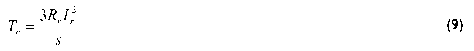
- Equations (6) to (9) also represent an electric static motor model for an asynchronous motor.
- Equations (10) to (14) represent an electric dynamic motor model for a permanent magnet motor.
- equation (15) and at least one of equations (16) and (17) are advantageously used.
- Claim 4 defines, by way of example, how mathematical links are made to determine whether an error exists or not.
- the basic idea of this specific method is, on the one hand with the aid of the engine model, to determine the engine torque resulting from the electrical variables on the motor shaft and the rotational speed. Equations (16) and (17) are used to determine a relationship between the differential pressure and the delivery flow on the one hand and between the pump pressure torque and the delivery flow on the other hand.
- a tolerance band by variance of at least one of the variables a h0 to a h2 , a t0 to a t2 , B and J in order to register an error only if this too is relevant to the operation.
- two hydraulic variables are determined by measuring and the determined values are inserted into the equations according to claim 4, so that then four error variables r 1 to r 4 result. Based on the combination of these error variables, the type of error is then determined on the basis of predetermined limit value combinations. This too is done automatically by electronic data processing.
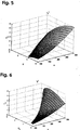
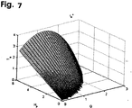
- the two aforementioned hydraulic variables are determined by measuring and the determined values are compared with predetermined values to determine the type of error, in which case the predefined values define an area in three-dimensional space It is determined whether or not the determined quantities lie on these areas (r * 1 to r * 4 ) and, based on the combination of the values, the type of error is determined on the basis of predetermined limit value combinations.
- the type of error can then be determined, for example, from the following table: Error type defect size r 1 , r 2 , r 3 , r 4 , comparison area r 1 * r 2 * r 3 * r 4 * Increased friction due to mechanical defects 1 0 1 1
- the surfaces formed in the three-dimensional space on the basis of predetermined values are typically space-curved surfaces whose values have previously been determined by the factory based on the respective unit or aggregate type and stored in the digital data memory on the aggregate side.
- the aforementioned comparison surfaces r * 1 to r * 4 are arranged in a three-dimensional space, which at r * 1 from the torque, the flow and the speed, at r * 2 from the differential pressure, the flow rate and the speed, for r * 3 of the torque, the differential pressure and the speed and for r * 4 from the torque, the differential pressure and the flow rate are formed.
- the variables defined in the table by the comparison surfaces r * 1 to r * 4 indicate the respective operating state, wherein the number 0 means that the respective value lies within the area defined by the predetermined values and 1 outside.
- the error combination defined in the table due to increased friction due to mechanical defects can mean bearing damage or an otherwise caused increased frictional resistance between the rotating parts and the stationary parts of the aggregate.
- the under the generic term reduced promotion / missing differential pressure marked error combination can be, for example, by error or wear on the pump impeller or an obstacle in the pump Einoder Exhaust caused.
- defect in the intake / missing flow error combination can be caused for example by defect of the ring seal at the suction of the pump.
- the operating states designated in the table by the variables R 1 to R 4 are based on mathematical calculations of fault parameters r 1 to r 4 according to the equations (19) to (22), wherein the corresponding error amount becomes zero when a correct operation is present and the value 1 in case of error.
- the table is to be understood in terms of the type of error in a similar manner as described above.
- each of the error quantities r 1 to r 4 represents a distance to the corresponding areas r * 1 to r * 4 .
- the error quantities do not necessarily correspond to the areas r * 1 to r * 4 .
- the error quantities r 1 to r 4 correspond to the equations (19) to (22) and correspond to the areas r * 1 to r * 4 in the FIGS. 4 to 9 ,
- the pump unit when a fault is detected, the pump unit is actuated with a different speed, in order then to be able to define the detected error more precisely on the basis of the resulting measuring results.
- a sensor for detecting the voltage applied to the motor supply voltage and the supply current and for detecting the differential pressure applied by the pump and the flow rate.
- an evaluation device to be provided which in the form of digital data processing, for. B. a microprocessor may be formed, in which the inventive method is implemented by software.
- an electronic memory is also to be provided. In modern frequency converter controlled pump units all the aforementioned hardware requirements are already in place, so that is only to ensure sufficient dimensioning of the electronic data processing system, in particular the storage means and the evaluation device.
- All components are preferably an integral part of the motor and / or pump electronics, so that constructively so far no further precautions are necessary to carry out the method according to the invention.
- Another embodiment may be a separate module provided in a panel or control panel, in the same way as a motor protection switch, but with the monitoring and diagnostic features as described above.
- centrifugal pumps as can be seen from the mechanical-hydraulic pump model.
- Such pumps may be, for example, industrial pumps, submersible pumps for sewage or water supply and heating circulation pumps.
- Particularly advantageous is a diagnostic system according to the invention in canned pumps, since through early fault detection, the looping through of the can and thus outlet of the pumped liquid, eg. B. in the living area, preventively prevented.
- the mechanical-hydraulic pump model In the application of the invention in Verdrängerpumpen Scheme the mechanical-hydraulic pump model must be adjusted according to the different physical relationships. The same applies to the use of other engine types for the electric motor model.
- means are provided for generating and transmitting at least one error message to a display element arranged on the pump unit or elsewhere, whether in the form of one or more indicator lights or a display with an alphanumeric display.
- the transmission can be wireless, for example via infrared or radio but also wired, preferably in digital form.
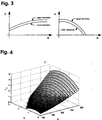
- FIG. 1 A simplified method, which does not belong to the invention is based on Fig. 1 shown.
- the variable electrical power-determining variables flow, here the voltage V abc and the current i abc -
- the product of these quantities defines the electrical power absorbed by the engine.
- the torque T e on the shaft of the motor and the rotational speed ⁇ derivable from the engine as they result arithmetically on the basis of the engine model.
Landscapes
- Engineering & Computer Science (AREA)
- Mechanical Engineering (AREA)
- General Engineering & Computer Science (AREA)
- Control Of Positive-Displacement Pumps (AREA)
- Control Of Electric Motors In General (AREA)
- Fluid-Pressure Circuits (AREA)
Claims (10)
- Procédé pour la détermination d'erreurs dans le fonctionnement d'un groupe moto-pompe, selon lequel au moins deux grandeurs électriques du moteur, fixant la puissance électrique du moteur, et au moins une grandeur hydraulique variable de la pompe ainsi qu'au moins une grandeur hydraulique supplémentaire fixant la puissance de la pompe sont détectées et, d'une part, les deux grandeurs électriques du moteur, fixant la puissance électrique du moteur, sont combinées mathématiquement, en vue de l'obtention d'au moins une valeur de comparaison et, d'autre part, la au moins une grandeur hydraulique variable de la pompe ainsi que la au moins une grandeur hydraulique supplémentaire, fixant la puissance de la pompe, sont combinées mathématiquement en vue de l'obtention d'au moins une valeur de comparaison, étant précisé que pour la combinaison mathématique, on emploie un modèle mathématique de moteur électrique (1) en liaison avec un modèle mathématique de pompe mécanique-hydraulique (3) et qu'à partir des résultats des combinaisons mathématiques, il est déterminé, par comparaison avec des valeurs pré-établies, si une erreur est présente ou non, la tension d'entrée Vabc et le courant moteur iabc étant utilisés comme valeurs d'entrée pour le modèle de moteur (1) pour déterminer le couple Te agissant sur l'arbre moteur, caractérisé en ce que la vitesse de rotation de l'arbre ω est déterminée à partir du modèle de moteur et ces valeurs dérivées du modèle de moteur (1) ainsi que les grandeurs déterminées par capteurs de la hauteur de refoulement H (pression différentielle) ainsi que du débit de refoulement Q sont combinées mathématiquement dans le modèle de pompe mécanique-hydraulique (3).
- Procédé selon la revendication 1, caractérisé en ce que, lorsque la présence d'une erreur est déterminée, il est encore déterminé de quelle erreur il s'agit.
- Procédé selon l'une des revendications précédentes, caractérisé en ce que le modèle de moteur électrique (1) est formé par les équations suivantes :


OU


dans lesquelles
isd est le courant du moteur dans la direction d
isq est le courant du moteur dans la direction q
ψrd est le flux magnétique du rotor dans la direction d
ψrq est le flux magnétique du rotor dans la direction q
Te est le couple du moteur
Vsd est la tension d'alimentation du moteur dans la direction d
Vsq est la tension d'alimentation du moteur dans la direction q
ω est la vitesse angulaire du rotor et de la roue à aubes
R's est la résistance équivalente de l'enroulement du stator
R'r est la résistance équivalente de l'enroulement du rotor
Lm est la résistance de couplage inductive entre l'enroulement du stator et l'enroulement du rotor
L's est la résistance équivalente inductive de l'enroulement du stator
Lr est la résistance inductive de l'enroulement du rotor
Zp est le nombre de paires de pôles
Is est le courant de phase
Vs est la tension de phase
ωs est la fréquence de la tension d'alimentation
ω est la vitesse de rotation réelle du rotor et de la roue à aubes
s est le glissement du moteur
Zs(s) est l'impédance du stator
Zr(s) est l'impédance du rotor
Rr est la résistance équivalente de l'enroulement du rotor
Rs est la résistance équivalente de l'enroulement du stator
Ls est la résistance inductive de l'enroulement du stator,
d et q étant deux directions perpendiculaires l'une à l'autre perpendiculairement à l'arbre du moteur,
et en ce que le modèle de pompe/moteur mécanique-hydraulique est formé par une équation
et au moins l'une des équations

dans lesquelles

Tp est le couple de rotation de la pompe
J est le moment d'inertie du rotor, de la roue à aubes et du liquide transporté pris dans la route à aubes
B est la constante de frottement
Q est le débit de refoulement de la pompe
Hp est la pression différentielle engendrée par la pompe
a h2, a h1,a h0 sont les paramètres qui dépeignent la relation entre la vitesse de rotation de la roue à aubes, le débit de refoulement et la pression différentielle, et
a t2,a t1,a t0 sont les paramètres qui dépeignent la relation entre la vitesse de rotation de la roue à aubes, le débit de refoulement et le moment d'inertie. - Procédé selon la revendication 3, caractérisé en ce que, dans les équations (16) et (17), les grandeurs ah0- ah2 et at0-at2 sont établies, ainsi que dans l'équation (15) les grandeurs B et J, en ce qu'à partir du modèle de moteur électrique (1) conforme aux équations (1) - (5) ou (6) - (9) ou (10) - (14), un couple de moteur (Te) est déterminé et la vitesse de rotation est calculée d'après les équations (1) - (5) ou (6) - (9) ou (10) - (14), après quoi, à l'aide des équations (16) et (17), une relation entre la pression différentielle et le débit de refoulement, d'une part, et entre le couple de pompe et le débit de refoulement d'autre part, est déterminée.
- Procédé selon la revendication 3, caractérisé en ce qu'une bande de tolérance est établie par variance d'au moins l'une des grandeurs ah0- ah2 et at0-at2 et B et J.
- Procédé selon l'une des revendications précédentes, caractérisé en ce que les valeurs déterminées sont portées dans les équations selon la revendication 4, de telle manière que plusieurs grandeurs d'erreur (r1 - r4) en résultent, étant précisé qu'à partir de la combinaison des grandeurs d'erreur la nature de l'erreur est déterminée sur la base de combinaisons de valeurs limites pré-établies.
- Procédé selon l'une des revendications précédentes, caractérisé en ce que les valeurs déterminées ou des valeurs dérivées de celles-ci sont comparées à des valeurs pré-établies, les valeurs pré-établies définissant chacune une surface, étant précisé qu'il est déterminé si les grandeurs déterminées ou les grandeurs dérivées de celles-ci sont situées ou non sur l'une de ces surfaces (r*1 - r*4), et que sur la base de la combinaison des grandeurs d'erreur, la nature de l'erreur est déterminée à partir de combinaisons pré-établies de valeurs limites.
- Procédé selon l'une des revendications précédentes, caractérisé en ce que la détermination de la nature de l'erreur s'effectue à partir du tableau suivant :
Nature de l'erreur Grandeur d'erreur r1, r2, r3, r4, Surface de comparaison r1* r2* r3* r4* Frottement accru dû à des défauts mécaniques 1 0 1 1 Refoulement réduit/ pression différentielle insuffisante 0 1 1 1 Défaut dans la zone d'aspiration/ débit de refoulement insuffisant 1 1 0 1 Arrêt du refoulement 1 1 1 1 - Procédé selon l'une des revendications précédentes, caractérisé en ce que, lors de la détermination d'une erreur, le groupe moto-pompe est excité dans le sens d'une vitesse de rotation modifiée, pour à partir des résultats de mesure ou se présentant alors, spécifier avec plus de précision l'erreur déterminée.
- Procédé selon l'une des revendications précédentes, caractérisé en ce que les grandeurs r1 - r4 sont définies par les équations :


dans lesquelles
k1 , k2 , k3 sont des constantes,
q1, q2, q3, q4 sont des constantes,
Q' est le débit de refoulement calculé sur la base de la vitesse de rotation instantanée et de la pression différentielle mesurée,
ω̂ 1 est la vitesse de rotation calculée du rotor sur la base des équations mécaniques-hydrauliques (15) et (17),
ω̂3 est la vitesse de rotation calculée du rotor sur la base des équations (15), (16) et (17),
ω̂4 est la vitesse de rotation calculée du rotor sur la base des équations (15), (16) et (17),
ω' est la vitesse de rotation calculée du rotor sur la base de la pression différentielle et du débit de refoulement mesuré,
r1 - r4 sont des grandeurs d'erreur, et
r1*- r4* sont des surfaces définies par trois variables, qui représentent un fonctionnement exempt d'erreurs de la pompe.
Priority Applications (7)
| Application Number | Priority Date | Filing Date | Title |
|---|---|---|---|
| EP04002979.5A EP1564411B2 (fr) | 2004-02-11 | 2004-02-11 | Procédé de détection des erreurs de fonctionnement d'une unité de pompage |
| AT04002979T ATE389807T1 (de) | 2004-02-11 | 2004-02-11 | Verfahren zur ermittlung von fehlern beim betrieb eines pumpenaggregates |
| DE502004006565T DE502004006565D1 (de) | 2004-02-11 | 2004-02-11 | Verfahren zur Ermittlung von Fehlern beim Betrieb eines Pumpenaggregates |
| PCT/EP2005/001193 WO2005078287A1 (fr) | 2004-02-11 | 2005-02-05 | Procede de determination d'anomalies lors du fonctionnement d'un groupe de pompage |
| US10/597,892 US8070457B2 (en) | 2004-02-11 | 2005-02-05 | Method for determining faults during the operation of a pump unit |
| CN200580008075.3A CN1938520B (zh) | 2004-02-11 | 2005-02-05 | 用于确定泵单元运行时的故障的方法 |
| US13/284,049 US8353676B2 (en) | 2004-02-11 | 2011-10-28 | Method for determining faults during the operation of a pump unit |
Applications Claiming Priority (1)
| Application Number | Priority Date | Filing Date | Title |
|---|---|---|---|
| EP04002979.5A EP1564411B2 (fr) | 2004-02-11 | 2004-02-11 | Procédé de détection des erreurs de fonctionnement d'une unité de pompage |
Publications (3)
| Publication Number | Publication Date |
|---|---|
| EP1564411A1 EP1564411A1 (fr) | 2005-08-17 |
| EP1564411B1 EP1564411B1 (fr) | 2008-03-19 |
| EP1564411B2 true EP1564411B2 (fr) | 2015-08-05 |
Family
ID=34684659
Family Applications (1)
| Application Number | Title | Priority Date | Filing Date |
|---|---|---|---|
| EP04002979.5A Expired - Lifetime EP1564411B2 (fr) | 2004-02-11 | 2004-02-11 | Procédé de détection des erreurs de fonctionnement d'une unité de pompage |
Country Status (6)
| Country | Link |
|---|---|
| US (2) | US8070457B2 (fr) |
| EP (1) | EP1564411B2 (fr) |
| CN (1) | CN1938520B (fr) |
| AT (1) | ATE389807T1 (fr) |
| DE (1) | DE502004006565D1 (fr) |
| WO (1) | WO2005078287A1 (fr) |
Cited By (1)
| Publication number | Priority date | Publication date | Assignee | Title |
|---|---|---|---|---|
| DE102023204527A1 (de) * | 2023-05-15 | 2024-11-21 | BSH Hausgeräte GmbH | Verfahren zur Bestimmung eines Druckverlustes einer Entwässerungspumpe und hierzu geeignetes wasserführendes Haushaltsgerät |
Families Citing this family (37)
| Publication number | Priority date | Publication date | Assignee | Title |
|---|---|---|---|---|
| US8469675B2 (en) | 2004-08-26 | 2013-06-25 | Pentair Water Pool And Spa, Inc. | Priming protection |
| US7690897B2 (en) * | 2006-10-13 | 2010-04-06 | A.O. Smith Corporation | Controller for a motor and a method of controlling the motor |
| GB2447867B (en) * | 2007-03-29 | 2010-01-27 | Byzak Ltd | Sewage pump blockage detection |
| EP2039939B2 (fr) * | 2007-09-20 | 2020-11-18 | Grundfos Management A/S | Procédé de surveillance d'un dispositif de transformation d'énergie |
| DE102008063132B4 (de) * | 2008-12-24 | 2011-02-17 | Oerlikon Leybold Vacuum Gmbh | Verfahren zur Identifizierung eines Typs einer Vakuumpumpe |
| DE102009009231B9 (de) * | 2009-02-17 | 2013-06-27 | Human Med Ag | Einrichtung und Verfahren zum Zuführen einer Flüssigkeit zu medizinischen Zwecken an einen Operationsort |
| DE102009022107A1 (de) * | 2009-05-20 | 2010-11-25 | Ksb Ag | Verfahren und Vorrichtung zur Betriebspunktbestimmung einer Arbeitsmaschine |
| ITTO20090598A1 (it) * | 2009-07-31 | 2011-02-01 | Sema Elettronica S R L | Dispositivo per l'estrazione di acqua dal sottosuolo |
| CA2793482C (fr) * | 2011-11-01 | 2019-09-24 | Regal Beloit Epc Inc. | Detection de piege pour systeme de pompe a vitesse variable a l'aide d'un coefficient de charge |
| EP3869282B1 (fr) * | 2012-12-12 | 2023-06-07 | S. A. Armstrong Limited | Système de commande autodidacte et procédé d'optimisation d'une variable d'entrée consommable |
| AU2013204013B2 (en) | 2013-03-15 | 2015-09-10 | Franklin Electric Company, Inc. | System and method for operating a pump |
| GB2512084A (en) * | 2013-03-19 | 2014-09-24 | Control Tech Ltd | Pump control |
| DE102013211345B4 (de) | 2013-06-18 | 2022-12-01 | Robert Bosch Gmbh | Verfahren zur Zustandsüberwachung an Verdrängereinheiten |
| DE102013109411A1 (de) * | 2013-08-29 | 2015-03-05 | Prominent Gmbh | Verfahren zur Bestimmung von hydraulischen Parametern |
| US9230208B2 (en) | 2013-12-18 | 2016-01-05 | International Business Machines Corporation | Haptic-based artificial neural network training |
| CN106066621A (zh) * | 2016-07-27 | 2016-11-02 | 霍州煤电集团有限责任公司 | 一种煤矿中央泵房水泵的预判维护及远程控制方法 |
| US11286917B2 (en) | 2016-10-21 | 2022-03-29 | Franklin Electric Co., Inc. | Motor drive system and method |
| EP4365453A3 (fr) * | 2016-12-30 | 2024-07-10 | Grundfos Holding A/S | Procédé de fonctionnement d'un groupe motopompe à commande électronique |
| USD872847S1 (en) | 2018-02-28 | 2020-01-14 | S. C. Johnson & Son, Inc. | Dispenser |
| USD872245S1 (en) | 2018-02-28 | 2020-01-07 | S. C. Johnson & Son, Inc. | Dispenser |
| USD881365S1 (en) | 2018-02-28 | 2020-04-14 | S. C. Johnson & Son, Inc. | Dispenser |
| USD880670S1 (en) | 2018-02-28 | 2020-04-07 | S. C. Johnson & Son, Inc. | Overcap |
| KR102103146B1 (ko) * | 2018-03-14 | 2020-04-22 | (주)아이티공간 | 구동부의 정밀 예지 보전방법 |
| KR102103151B1 (ko) * | 2018-03-14 | 2020-04-22 | (주)아이티공간 | 구동부의 정밀 예지 보전방법 |
| USD853548S1 (en) | 2018-05-07 | 2019-07-09 | S. C. Johnson & Son, Inc. | Dispenser |
| USD852938S1 (en) | 2018-05-07 | 2019-07-02 | S. C. Johnson & Son, Inc. | Dispenser |
| EP3567256B1 (fr) * | 2018-05-11 | 2025-07-02 | Grundfos Holding A/S | Module de surveillance et procédé permettant d'identifier un scénario de fonctionnement dans une station de pompage des eaux usées |
| CN111089819B (zh) * | 2019-12-17 | 2023-05-02 | 重庆南方数控设备股份有限公司 | 基于血流变仪的泵工作状态预判检测的血液检测方法 |
| US11454225B2 (en) | 2020-04-29 | 2022-09-27 | Halliburton Energy Services, Inc. | Single motor-driven dual pump detachment monitoring algorithm |
| RU2743866C1 (ru) * | 2020-06-30 | 2021-03-01 | Федеральное государственное бюджетное образовательное учреждение высшего образования "Омский государственный технический университет" (ОмГТУ) | Способ определения давления центробежного насоса с асинхронным электроприводом |
| US12305650B2 (en) | 2020-07-24 | 2025-05-20 | Eaton Intelligent Power Limited | Control system for a fluid management system |
| EP4019779A1 (fr) | 2020-12-23 | 2022-06-29 | Grundfos Holding A/S | Système et procédé de surveillance de pompe pour associer un état de fonctionnement actuel d'un système de pompe à un ou plusieurs scénarios de panne |
| CN112983844B (zh) * | 2021-03-01 | 2021-10-08 | 合肥恒大江海泵业股份有限公司 | 一种潜水电泵监测控制系统 |
| CN114876782B (zh) * | 2022-05-13 | 2024-03-12 | 三一汽车制造有限公司 | 液压泵故障检测方法、装置及作业机械 |
| DE102022113913A1 (de) | 2022-06-02 | 2023-12-07 | Liebherr-Aerospace Lindenberg Gmbh | Vorrichtung und Verfahren zur Zustandsüberwachung einer Elektromotorpumpe |
| DE102023111782A1 (de) | 2023-05-05 | 2024-11-07 | KSB SE & Co. KGaA | Verfahren zur Detektion von Kavitation und/oder einer Lufteinperlung bzw. Lufteinströmung innerhalb eines hydraulischen Systems |
| CN117533511A (zh) * | 2023-11-23 | 2024-02-09 | 中国航发西安动力控制科技有限公司 | 一种电动燃油系统中飞机油箱故障诊断与处理装置及方法 |
Family Cites Families (15)
| Publication number | Priority date | Publication date | Assignee | Title |
|---|---|---|---|---|
| EP0231295A1 (fr) | 1985-08-07 | 1987-08-12 | MARR, Edward Howell | Dispositif de terminaison de cable |
| US4913625A (en) * | 1987-12-18 | 1990-04-03 | Westinghouse Electric Corp. | Automatic pump protection system |
| JPH02206469A (ja) * | 1989-02-03 | 1990-08-16 | Aisin Seiki Co Ltd | ポンピング装置 |
| KR910006616A (ko) * | 1989-09-29 | 1991-04-29 | 이헌조 | 펌프모터의 운전제어회로 |
| US5447414A (en) * | 1994-05-27 | 1995-09-05 | Emerson Electric Co. | Constant air flow control apparatus and method |
| US5725357A (en) * | 1995-04-03 | 1998-03-10 | Ntn Corporation | Magnetically suspended type pump |
| JPH10147236A (ja) * | 1996-11-20 | 1998-06-02 | Aisin Seiki Co Ltd | 流体圧源装置 |
| DE19725074C2 (de) * | 1997-06-13 | 2001-10-18 | Ekl Ag | Alarmmodul |
| US6464464B2 (en) * | 1999-03-24 | 2002-10-15 | Itt Manufacturing Enterprises, Inc. | Apparatus and method for controlling a pump system |
| US6144178A (en) * | 1999-08-05 | 2000-11-07 | International Business Machines Corporation | Disk drive with controlled reduced internal pressure |
| CA2404636A1 (fr) * | 2000-03-27 | 2001-10-04 | The Cleveland Clinic Foundation | Systeme de controle chronique du rendement des pompes sanguines rotodynamiques |
| DE10116339B4 (de) * | 2001-04-02 | 2005-05-12 | Danfoss Drives A/S | Verfahren zum Betreiben einer Zentrifugalpumpe |
| EP1255174A1 (fr) * | 2001-04-30 | 2002-11-06 | Starite S.p.A. | Pompe électrique avec dispositif marche/arrêt automatique |
| US6655922B1 (en) * | 2001-08-10 | 2003-12-02 | Rockwell Automation Technologies, Inc. | System and method for detecting and diagnosing pump cavitation |
| SE0104317L (sv) * | 2001-12-20 | 2002-11-26 | Itt Mfg Enterprises Inc | Avkänningsanordning för vätskeflödet i ett pumputlopp avsedd att styra strömtillförseln till den elektriskt drivan pumpmotorn |
-
2004
- 2004-02-11 EP EP04002979.5A patent/EP1564411B2/fr not_active Expired - Lifetime
- 2004-02-11 AT AT04002979T patent/ATE389807T1/de not_active IP Right Cessation
- 2004-02-11 DE DE502004006565T patent/DE502004006565D1/de not_active Expired - Lifetime
-
2005
- 2005-02-05 CN CN200580008075.3A patent/CN1938520B/zh not_active Expired - Fee Related
- 2005-02-05 US US10/597,892 patent/US8070457B2/en not_active Expired - Fee Related
- 2005-02-05 WO PCT/EP2005/001193 patent/WO2005078287A1/fr not_active Ceased
-
2011
- 2011-10-28 US US13/284,049 patent/US8353676B2/en not_active Expired - Fee Related
Cited By (1)
| Publication number | Priority date | Publication date | Assignee | Title |
|---|---|---|---|---|
| DE102023204527A1 (de) * | 2023-05-15 | 2024-11-21 | BSH Hausgeräte GmbH | Verfahren zur Bestimmung eines Druckverlustes einer Entwässerungspumpe und hierzu geeignetes wasserführendes Haushaltsgerät |
Also Published As
| Publication number | Publication date |
|---|---|
| CN1938520A (zh) | 2007-03-28 |
| US20080240931A1 (en) | 2008-10-02 |
| US8353676B2 (en) | 2013-01-15 |
| US20120101788A1 (en) | 2012-04-26 |
| DE502004006565D1 (de) | 2008-04-30 |
| EP1564411A1 (fr) | 2005-08-17 |
| ATE389807T1 (de) | 2008-04-15 |
| EP1564411B1 (fr) | 2008-03-19 |
| US8070457B2 (en) | 2011-12-06 |
| WO2005078287A1 (fr) | 2005-08-25 |
| CN1938520B (zh) | 2011-07-20 |
Similar Documents
| Publication | Publication Date | Title |
|---|---|---|
| EP1564411B2 (fr) | Procédé de détection des erreurs de fonctionnement d'une unité de pompage | |
| EP2145112B1 (fr) | Dispositif et procédé de surveillance de dysfonctionnements | |
| EP3449132B1 (fr) | Procédé de détection d'un état de fonctionnement anormal d'un groupe de pompage | |
| EP3803122B1 (fr) | Procédé pour déterminer ou surveiller l'état d'une pompe à vis excentrique | |
| EP2039939B1 (fr) | Procédé de surveillance d'un dispositif de transformation d'énergie | |
| EP0895010B1 (fr) | Procédé pour contrôler l'état d'une garniture mécanique d'étanchéité | |
| EP2024712B1 (fr) | Dispositif pour la transmission de valeurs de mesure | |
| WO2016173896A1 (fr) | Dispositif de pompe et procédé pour actionner une pompe pour liquides | |
| EP3242035B1 (fr) | Procédé de fonctionnement d'au moins un groupe motopompe parmi une pluralité de groupes motopompe | |
| DE102011010218B4 (de) | Verfahren zum Regeln des Drucks eines mittels einer drehzahlgeregelten Pumpe geförderten Fluids | |
| WO2010133425A1 (fr) | Procédé et dispositif de détermination d'un point de fonctionnement d'une machine de travail | |
| DE102007039699B4 (de) | Verfahren zum Überwachen von Schwingungspegelwerten bei einem Industriegetriebe und System | |
| EP2702459A1 (fr) | Moyens de commande pour piloter un convertisseur de fréquence et procédé de commande correspondant | |
| EP2696175A1 (fr) | Procédé de détection du débit d'une pompe à centrifuge | |
| EP0943805B1 (fr) | Procédé et capteur pour la détection de la cavitation ainsi qu'un dispositif comprenant un tel capteur | |
| EP3841366B1 (fr) | Procédé et système pour la détermination directe d'un endommagement théorique d'au moins un organe d'un dispositif | |
| WO2016009043A1 (fr) | Détermination du courant d'alimentation d'une pompe | |
| EP1825147B1 (fr) | Procede de fonctionnement d'un compresseur alimente par convertisseur | |
| EP2122177B1 (fr) | Groupe motopompe | |
| WO2016166114A1 (fr) | Pompe et procédé pour faire fonctionner une pompe pour liquides | |
| WO2004005939A1 (fr) | Dispositif permettant de determiner la vitesse de rotation d'une partie de machine en rotation | |
| EP2500579A1 (fr) | Détection de la cavitation et de l'entraînement de gaz dans une pompe électrique centrifuge | |
| EP3120203B1 (fr) | Dispositif et procédé servant à identifier des anomalies dans des machines | |
| EP4357749B1 (fr) | Procédé de détection automatique d'usure, de dommages de denture et/ou de dommages de palier sur une boîte de vitesses | |
| DE102004044185A1 (de) | Verfahren und Vorrichtung zum Ermitteln eines Fehlerzustandes eines rotierenden Verdichters |
Legal Events
| Date | Code | Title | Description |
|---|---|---|---|
| PUAI | Public reference made under article 153(3) epc to a published international application that has entered the european phase |
Free format text: ORIGINAL CODE: 0009012 |
|
| AK | Designated contracting states |
Kind code of ref document: A1 Designated state(s): AT BE BG CH CY CZ DE DK EE ES FI FR GB GR HU IE IT LI LU MC NL PT RO SE SI SK TR |
|
| AX | Request for extension of the european patent |
Extension state: AL LT LV MK |
|
| 17P | Request for examination filed |
Effective date: 20051221 |
|
| AKX | Designation fees paid |
Designated state(s): AT BE BG CH CY CZ DE DK EE ES FI FR GB GR HU IE IT LI LU MC NL PT RO SE SI SK TR |
|
| 17Q | First examination report despatched |
Effective date: 20060502 |
|
| GRAP | Despatch of communication of intention to grant a patent |
Free format text: ORIGINAL CODE: EPIDOSNIGR1 |
|
| GRAS | Grant fee paid |
Free format text: ORIGINAL CODE: EPIDOSNIGR3 |
|
| GRAA | (expected) grant |
Free format text: ORIGINAL CODE: 0009210 |
|
| AK | Designated contracting states |
Kind code of ref document: B1 Designated state(s): AT BE BG CH CY CZ DE DK EE ES FI FR GB GR HU IE IT LI LU MC NL PT RO SE SI SK TR |
|
| REG | Reference to a national code |
Ref country code: GB Ref legal event code: FG4D Free format text: NOT ENGLISH |
|
| REG | Reference to a national code |
Ref country code: CH Ref legal event code: EP |
|
| REF | Corresponds to: |
Ref document number: 502004006565 Country of ref document: DE Date of ref document: 20080430 Kind code of ref document: P |
|
| REG | Reference to a national code |
Ref country code: IE Ref legal event code: FG4D Free format text: LANGUAGE OF EP DOCUMENT: GERMAN |
|
| REG | Reference to a national code |
Ref country code: SE Ref legal event code: TRGR |
|
| NLV1 | Nl: lapsed or annulled due to failure to fulfill the requirements of art. 29p and 29m of the patents act | ||
| PG25 | Lapsed in a contracting state [announced via postgrant information from national office to epo] |
Ref country code: SI Free format text: LAPSE BECAUSE OF FAILURE TO SUBMIT A TRANSLATION OF THE DESCRIPTION OR TO PAY THE FEE WITHIN THE PRESCRIBED TIME-LIMIT Effective date: 20080319 |
|
| REG | Reference to a national code |
Ref country code: HU Ref legal event code: AG4A Ref document number: E003577 Country of ref document: HU |
|
| REG | Reference to a national code |
Ref country code: IE Ref legal event code: FD4D |
|
| PG25 | Lapsed in a contracting state [announced via postgrant information from national office to epo] |
Ref country code: SK Free format text: LAPSE BECAUSE OF FAILURE TO SUBMIT A TRANSLATION OF THE DESCRIPTION OR TO PAY THE FEE WITHIN THE PRESCRIBED TIME-LIMIT Effective date: 20080319 Ref country code: PT Free format text: LAPSE BECAUSE OF FAILURE TO SUBMIT A TRANSLATION OF THE DESCRIPTION OR TO PAY THE FEE WITHIN THE PRESCRIBED TIME-LIMIT Effective date: 20080826 Ref country code: ES Free format text: LAPSE BECAUSE OF FAILURE TO SUBMIT A TRANSLATION OF THE DESCRIPTION OR TO PAY THE FEE WITHIN THE PRESCRIBED TIME-LIMIT Effective date: 20080630 Ref country code: CZ Free format text: LAPSE BECAUSE OF FAILURE TO SUBMIT A TRANSLATION OF THE DESCRIPTION OR TO PAY THE FEE WITHIN THE PRESCRIBED TIME-LIMIT Effective date: 20080319 |
|
| PG25 | Lapsed in a contracting state [announced via postgrant information from national office to epo] |
Ref country code: NL Free format text: LAPSE BECAUSE OF FAILURE TO SUBMIT A TRANSLATION OF THE DESCRIPTION OR TO PAY THE FEE WITHIN THE PRESCRIBED TIME-LIMIT Effective date: 20080319 Ref country code: RO Free format text: LAPSE BECAUSE OF FAILURE TO SUBMIT A TRANSLATION OF THE DESCRIPTION OR TO PAY THE FEE WITHIN THE PRESCRIBED TIME-LIMIT Effective date: 20080319 |
|
| PLBI | Opposition filed |
Free format text: ORIGINAL CODE: 0009260 |
|
| ET | Fr: translation filed | ||
| PLAX | Notice of opposition and request to file observation + time limit sent |
Free format text: ORIGINAL CODE: EPIDOSNOBS2 |
|
| 26 | Opposition filed |
Opponent name: WILO SE Effective date: 20081215 |
|
| PG25 | Lapsed in a contracting state [announced via postgrant information from national office to epo] |
Ref country code: DK Free format text: LAPSE BECAUSE OF FAILURE TO SUBMIT A TRANSLATION OF THE DESCRIPTION OR TO PAY THE FEE WITHIN THE PRESCRIBED TIME-LIMIT Effective date: 20080319 Ref country code: IE Free format text: LAPSE BECAUSE OF FAILURE TO SUBMIT A TRANSLATION OF THE DESCRIPTION OR TO PAY THE FEE WITHIN THE PRESCRIBED TIME-LIMIT Effective date: 20080319 |
|
| PG25 | Lapsed in a contracting state [announced via postgrant information from national office to epo] |
Ref country code: BG Free format text: LAPSE BECAUSE OF FAILURE TO SUBMIT A TRANSLATION OF THE DESCRIPTION OR TO PAY THE FEE WITHIN THE PRESCRIBED TIME-LIMIT Effective date: 20080619 Ref country code: EE Free format text: LAPSE BECAUSE OF FAILURE TO SUBMIT A TRANSLATION OF THE DESCRIPTION OR TO PAY THE FEE WITHIN THE PRESCRIBED TIME-LIMIT Effective date: 20080319 |
|
| PLAF | Information modified related to communication of a notice of opposition and request to file observations + time limit |
Free format text: ORIGINAL CODE: EPIDOSCOBS2 |
|
| PLBB | Reply of patent proprietor to notice(s) of opposition received |
Free format text: ORIGINAL CODE: EPIDOSNOBS3 |
|
| BERE | Be: lapsed |
Owner name: GRUNDFOS A/S Effective date: 20090228 |
|
| PG25 | Lapsed in a contracting state [announced via postgrant information from national office to epo] |
Ref country code: CY Free format text: LAPSE BECAUSE OF FAILURE TO SUBMIT A TRANSLATION OF THE DESCRIPTION OR TO PAY THE FEE WITHIN THE PRESCRIBED TIME-LIMIT Effective date: 20080319 Ref country code: MC Free format text: LAPSE BECAUSE OF NON-PAYMENT OF DUE FEES Effective date: 20090228 |
|
| REG | Reference to a national code |
Ref country code: CH Ref legal event code: PL |
|
| PG25 | Lapsed in a contracting state [announced via postgrant information from national office to epo] |
Ref country code: CH Free format text: LAPSE BECAUSE OF NON-PAYMENT OF DUE FEES Effective date: 20090228 Ref country code: LI Free format text: LAPSE BECAUSE OF NON-PAYMENT OF DUE FEES Effective date: 20090228 |
|
| PG25 | Lapsed in a contracting state [announced via postgrant information from national office to epo] |
Ref country code: BE Free format text: LAPSE BECAUSE OF NON-PAYMENT OF DUE FEES Effective date: 20090228 |
|
| PG25 | Lapsed in a contracting state [announced via postgrant information from national office to epo] |
Ref country code: AT Free format text: LAPSE BECAUSE OF NON-PAYMENT OF DUE FEES Effective date: 20090211 |
|
| PG25 | Lapsed in a contracting state [announced via postgrant information from national office to epo] |
Ref country code: GR Free format text: LAPSE BECAUSE OF FAILURE TO SUBMIT A TRANSLATION OF THE DESCRIPTION OR TO PAY THE FEE WITHIN THE PRESCRIBED TIME-LIMIT Effective date: 20080620 |
|
| PG25 | Lapsed in a contracting state [announced via postgrant information from national office to epo] |
Ref country code: LU Free format text: LAPSE BECAUSE OF NON-PAYMENT OF DUE FEES Effective date: 20090211 |
|
| PLAP | Information related to despatch of examination report in opposition + time limit deleted |
Free format text: ORIGINAL CODE: EPIDOSDORE2 |
|
| PLAY | Examination report in opposition despatched + time limit |
Free format text: ORIGINAL CODE: EPIDOSNORE2 |
|
| PLAY | Examination report in opposition despatched + time limit |
Free format text: ORIGINAL CODE: EPIDOSNORE2 |
|
| PLBC | Reply to examination report in opposition received |
Free format text: ORIGINAL CODE: EPIDOSNORE3 |
|
| APBM | Appeal reference recorded |
Free format text: ORIGINAL CODE: EPIDOSNREFNO |
|
| APBP | Date of receipt of notice of appeal recorded |
Free format text: ORIGINAL CODE: EPIDOSNNOA2O |
|
| APAH | Appeal reference modified |
Free format text: ORIGINAL CODE: EPIDOSCREFNO |
|
| APBU | Appeal procedure closed |
Free format text: ORIGINAL CODE: EPIDOSNNOA9O |
|
| PUAH | Patent maintained in amended form |
Free format text: ORIGINAL CODE: 0009272 |
|
| STAA | Information on the status of an ep patent application or granted ep patent |
Free format text: STATUS: PATENT MAINTAINED AS AMENDED |
|
| 27A | Patent maintained in amended form |
Effective date: 20150805 |
|
| AK | Designated contracting states |
Kind code of ref document: B2 Designated state(s): AT BE BG CH CY CZ DE DK EE ES FI FR GB GR HU IE IT LI LU MC NL PT RO SE SI SK TR |
|
| REG | Reference to a national code |
Ref country code: DE Ref legal event code: R102 Ref document number: 502004006565 Country of ref document: DE |
|
| REG | Reference to a national code |
Ref country code: SE Ref legal event code: RPEO |
|
| REG | Reference to a national code |
Ref country code: FR Ref legal event code: PLFP Year of fee payment: 13 |
|
| REG | Reference to a national code |
Ref country code: FR Ref legal event code: PLFP Year of fee payment: 14 |
|
| REG | Reference to a national code |
Ref country code: FR Ref legal event code: PLFP Year of fee payment: 15 |
|
| PGFP | Annual fee paid to national office [announced via postgrant information from national office to epo] |
Ref country code: HU Payment date: 20220205 Year of fee payment: 19 Ref country code: GB Payment date: 20220221 Year of fee payment: 19 Ref country code: FI Payment date: 20220215 Year of fee payment: 19 Ref country code: DE Payment date: 20220221 Year of fee payment: 19 |
|
| PGFP | Annual fee paid to national office [announced via postgrant information from national office to epo] |
Ref country code: TR Payment date: 20220128 Year of fee payment: 19 Ref country code: SE Payment date: 20220221 Year of fee payment: 19 Ref country code: IT Payment date: 20220228 Year of fee payment: 19 Ref country code: FR Payment date: 20220221 Year of fee payment: 19 |
|
| REG | Reference to a national code |
Ref country code: DE Ref legal event code: R082 Ref document number: 502004006565 Country of ref document: DE |
|
| REG | Reference to a national code |
Ref country code: DE Ref legal event code: R119 Ref document number: 502004006565 Country of ref document: DE |
|
| REG | Reference to a national code |
Ref country code: SE Ref legal event code: EUG |
|
| GBPC | Gb: european patent ceased through non-payment of renewal fee |
Effective date: 20230211 |
|
| PG25 | Lapsed in a contracting state [announced via postgrant information from national office to epo] |
Ref country code: SE Free format text: LAPSE BECAUSE OF NON-PAYMENT OF DUE FEES Effective date: 20230212 Ref country code: FI Free format text: LAPSE BECAUSE OF NON-PAYMENT OF DUE FEES Effective date: 20230211 |
|
| PG25 | Lapsed in a contracting state [announced via postgrant information from national office to epo] |
Ref country code: HU Free format text: LAPSE BECAUSE OF NON-PAYMENT OF DUE FEES Effective date: 20230212 |
|
| PG25 | Lapsed in a contracting state [announced via postgrant information from national office to epo] |
Ref country code: GB Free format text: LAPSE BECAUSE OF NON-PAYMENT OF DUE FEES Effective date: 20230211 |
|
| PG25 | Lapsed in a contracting state [announced via postgrant information from national office to epo] |
Ref country code: IT Free format text: LAPSE BECAUSE OF NON-PAYMENT OF DUE FEES Effective date: 20230211 Ref country code: GB Free format text: LAPSE BECAUSE OF NON-PAYMENT OF DUE FEES Effective date: 20230211 Ref country code: FR Free format text: LAPSE BECAUSE OF NON-PAYMENT OF DUE FEES Effective date: 20230228 Ref country code: DE Free format text: LAPSE BECAUSE OF NON-PAYMENT OF DUE FEES Effective date: 20230901 |