EP1564104A1 - Accessoire pour brouette - Google Patents
Accessoire pour brouette Download PDFInfo
- Publication number
- EP1564104A1 EP1564104A1 EP05090022A EP05090022A EP1564104A1 EP 1564104 A1 EP1564104 A1 EP 1564104A1 EP 05090022 A EP05090022 A EP 05090022A EP 05090022 A EP05090022 A EP 05090022A EP 1564104 A1 EP1564104 A1 EP 1564104A1
- Authority
- EP
- European Patent Office
- Prior art keywords
- wheelbarrow
- superstructure
- linkage
- rear wall
- trough
- Prior art date
- Legal status (The legal status is an assumption and is not a legal conclusion. Google has not performed a legal analysis and makes no representation as to the accuracy of the status listed.)
- Withdrawn
Links
- 238000010276 construction Methods 0.000 claims abstract description 32
- 239000004744 fabric Substances 0.000 claims abstract description 20
- 239000002184 metal Substances 0.000 claims abstract description 6
- 239000004033 plastic Substances 0.000 claims abstract description 5
- 239000002023 wood Substances 0.000 claims abstract description 3
- 239000000835 fiber Substances 0.000 claims description 3
- OKTJSMMVPCPJKN-UHFFFAOYSA-N Carbon Chemical compound [C] OKTJSMMVPCPJKN-UHFFFAOYSA-N 0.000 claims description 2
- 229910052799 carbon Inorganic materials 0.000 claims description 2
- 239000002131 composite material Substances 0.000 claims description 2
- 239000011152 fibreglass Substances 0.000 claims description 2
- 239000012209 synthetic fiber Substances 0.000 claims 1
- 229920002994 synthetic fiber Polymers 0.000 claims 1
- 239000000463 material Substances 0.000 description 9
- 239000011324 bead Substances 0.000 description 3
- 239000000126 substance Substances 0.000 description 3
- 239000013590 bulk material Substances 0.000 description 2
- 238000004519 manufacturing process Methods 0.000 description 2
- 244000025254 Cannabis sativa Species 0.000 description 1
- 230000009286 beneficial effect Effects 0.000 description 1
- 238000003898 horticulture Methods 0.000 description 1
- 238000009434 installation Methods 0.000 description 1
Images

Classifications
-
- B—PERFORMING OPERATIONS; TRANSPORTING
- B62—LAND VEHICLES FOR TRAVELLING OTHERWISE THAN ON RAILS
- B62B—HAND-PROPELLED VEHICLES, e.g. HAND CARTS OR PERAMBULATORS; SLEDGES
- B62B1/00—Hand carts having only one axis carrying one or more transport wheels; Equipment therefor
- B62B1/18—Hand carts having only one axis carrying one or more transport wheels; Equipment therefor in which the load is disposed between the wheel axis and the handles, e.g. wheelbarrows
- B62B1/20—Hand carts having only one axis carrying one or more transport wheels; Equipment therefor in which the load is disposed between the wheel axis and the handles, e.g. wheelbarrows involving parts being collapsible, attachable, detachable or convertible
- B62B1/204—Detachable elements on the buckets, e.g. for increasing volume
-
- B—PERFORMING OPERATIONS; TRANSPORTING
- B62—LAND VEHICLES FOR TRAVELLING OTHERWISE THAN ON RAILS
- B62B—HAND-PROPELLED VEHICLES, e.g. HAND CARTS OR PERAMBULATORS; SLEDGES
- B62B2203/00—Grasping, holding, supporting the objects
- B62B2203/70—Comprising means for facilitating loading or unloading
-
- B—PERFORMING OPERATIONS; TRANSPORTING
- B62—LAND VEHICLES FOR TRAVELLING OTHERWISE THAN ON RAILS
- B62B—HAND-PROPELLED VEHICLES, e.g. HAND CARTS OR PERAMBULATORS; SLEDGES
- B62B2501/00—Manufacturing; Constructional features
- B62B2501/06—Materials used
Definitions
- the present invention is a construction based on conventional wheelbarrows can be mounted to the capacity of a Wheelbarrow to raise.
- the present application relates to a structural design for a Wheelbarrow raising the walls of the wheelbarrow pan and the Wheelbarrow tub at least partially surrounds.
- Wheelbarrows are used for the transport of light and heavy goods. Their capacity is limited by the size of the wheelbarrow tub. It is so dimensioned that loaded with heavy goods wheelbarrow with the power of a Person can be moved. If a wheelbarrow loaded with light goods, could the capacity significantly larger.
- FR 2 774 347 B1 The variant described in FR 2 774 347 B1 is also a rigid body construction for wheelbarrows with the already mentioned disadvantages in Terms of emptying. This variant is not lowered. Because the side walls the variant of FR 2 774 347 B1 consists of individual parts, the assembly appears to be less user friendly. The use of wire mesh as sidewalls Appears disadvantageous because the bulk material is easily caught in the mesh can.
- the object of the invention is to provide a To provide superstructure for wheelbarrows which is easily emptied.
- the present invention can be mounted on common wheelbarrow models; she surrounds the wheelbarrow tray at least partially, preferably completely and is on the front side lowered, so that the load can be dumped over the chute.
- the front or front side of a wheelbarrow is the side of a Wheelbarrow meant, from which the bulk material is dumped.
- back or back a wheelbarrow is hereinafter the side of a wheelbarrow meant by the Handles are located.
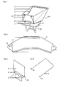
- FIG. 100 A first preferred embodiment of the construction according to the invention 100 is shown in FIG. It consists of a rigid rear wall 5 and a stable fabric 2, which together completely surround the wheelbarrow trough 21.
- a multi-part linkage 3 forms the supporting framework of the superstructure 100. The linkage can also be formed in one piece.
- the rear wall 5 has a rectangular basic shape with Recesses 9 at the lower left and right corner, so that the rear wall 5 in the Wheelbarrow trough 21 protrudes and rests on the two lateral Wannenwülsten.
- a U-profile 6 with opening mounted down.
- the linkage can also be articulated Mechanism on or at the side of the rear wall or directly on the wheelbarrow pan to be placed.
- the rear wall preferably consists of a sufficiently stable Material, such as wood, metal, plastic or a combination of these.
- the blank of the fabric 2 is shown in FIG.
- the side ends 14 of the fabric 2 become the rear wall 5 fixed.
- the side ends 14 of the fabric 2 is excess material in Form of two triangles 4 attached. These are in an upright position Structure 100 folded folded on the rear wall 5 fixed (see Figure 1) and are detached from the rear wall 5 for lowering the superstructure 100 (see FIG. 6).
- the fabric 2 should advantageously have sufficient strength and advantageously of synthetic or natural fiber or a combination of synthetic and natural fiber.
- the linkage 3 forms the supporting framework for the tissue 2. It consists in here illustrated example of three approximately 4 mm thick rods, the two lateral rods are about 110 cm and the middle is about 80 cm long.
- the linkage can also be made from a or more rods, with their strength and length suitable for the respective execution of the body structure can be selected.
- the rods are connected by angled plug-on attachments and together form a U-shape, as shown in Figure 4.
- Located at the ends of the two side bars each have a hinged mechanism 8, via which the linkage 3 movable with the rear wall 5 is connected.
- the rods should be made of a flexible Material, e.g. Carbon or fiberglass. Other preferred materials are Metal, composite, plastic, wood or combinations of the foregoing Materials.
- the U-profile 6 For mounting the rear wall 5 on the wheelbarrow trough 21, the U-profile 6 via the Wannenwulst hanged, the rear wall 5 in the hold of the wheelbarrow tray 21 protrudes.
- the U-profile 6 is connected to a clamping mechanism on the Wheelbarrow trough fixed. Further preferred mounting options are the screwing, the bracing or a combination of said Mounting options.
- the lower drawstring 7 is below the Wheelbarrow bead laid and stretched by an elastic elastic band. Around slipping of the fabric 2 on the front side of the wheelbarrow trough 21st to prevent, on the front side of the body 100 construction of the lower Drawstring 7 by means of S-shaped hooks 11 on the wheelbarrow trough 22nd held, as shown in Figures 5 and 6 can be seen.
- the linkage 3 is, after it has been inserted into the upper drawstring 1, in the Mounting holes 10 pushed in the rear wall 5. In an upright position the Wheelbarrow elevation or superstructure 100 runs the linkage 3 of the Rear wall 5 from diagonally up to the upper drawstring 1 (see Figure 1).
- the surplus substance 4 lies folded on the rear wall 5 and is e.g. with Velcro fasteners 15, snaps, Tensioning strap, a strap or an elastic band attached.
- Velcro fasteners 15 snaps, Tensioning strap, a strap or an elastic band attached.
- the preferably flexible linkage bends to the side and the wheelbarrow 20 can as as usual.
- the surplus substance 4 becomes again tightened and folded fixed to the rear wall 5. It is aimed at the Wheelbarrow 100 again on and the wheelbarrow 20 can be loaded again become.
- the rear wall 5 has a rectangular Basic shape with one at the level of the lower third horizontally on the back wall mounted U-profile with opening down. At the upper edge of the back wall There are two holders on the right and left, made of eyelets or hooks or Holes exist.
- the U-profile hung above the tub bead, with the rear wall outside the cargo space the wheelbarrow bucket hangs.
- the brackets with braced the handles of the wheelbarrow To fix the back wall, the brackets with braced the handles of the wheelbarrow.
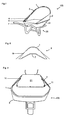
- FIGS. 7 to 8 A further preferred embodiment of the construction according to the invention 100 is shown in FIGS. 7 to 8. This embodiment is different from the already discussed embodiment in that on the one hand to the Rear wall has been omitted and on the other hand, a substantially arcuate Linkage 3 is used.
- the lowering mechanism as illustrated in the above variants, may be so be modified so that the articulated mechanism further away from the rear wall is positioned.
- a lowering of the body construction is also without excess material 4 possible.
- the height of the rear wall 5 can be chosen arbitrarily can, so that building structures of different sizes result, which for different user groups or applications may be suitable.
- completely dispensed with the rear wall become. While this is the increase in volume of the wheelbarrow 20 lower.
- the Volume increase achieved thereby is particularly suitable for use in small to medium gardens.
- embodiments without a back wall have the Advantage that it folded in a degraded state saves space can be, since they mainly consist of linkage 3 and fabric 2.
- the weight of such Construction structures significantly reduced. Also the material and manufacturing costs are therefore lower.
- An advantage of this variant are the small pack size in degraded state, the light weight of the body structure as well as lower Material and manufacturing costs.
- the linkage 3 in the middle section in be substantially arcuate.
- the cutting of the Fabric 2 and the course of the upper tunnel 1 (see Figure 8). this has in particular the advantage that the load acting on the tunnel 1 more uniform is distributed.
- the fabric 2 is preferably cut in such a way that that it expires wedge-shaped towards the back of the wheelbarrow 20.
- the linkage 3 is now on the upper edge of the wheelbarrow trough 21 via a clamping mechanism 12 fixed, which is hinged pivotally.
- the cords 13 solved so that the linkage 3 with fabric 2 depending on the dimensions on the Wheelbarrow tub edge or outside it falls over.
- the construction of the invention leads to a considerable Capacity increase of standard wheelbarrows.
- the wheelbarrow raise suitable for light cargo such as Foliage or grass clippings. She can in all Be used in areas where larger quantities of light goods of Hand must be transported, such. in horticulture or Caretakers, in cemeteries or in private gardens. Due to the Capacity increase will reduce the number of transport routes, which is a significant Saves time and labor. The low weight of the cargo leads to an insignificant physical burden.
- the wheelbarrow lift can open the common wheelbarrow models, preferably those with a tub bead, to be assembled.
- the simple assembly and disassembly of the wheelbarrow increase, the significant increase in the Capacity and the continued unrestricted emptying allow a Significant reduction in the time and effort required to transport light weight Bulk materials.
- the lowerable wheelbarrow can be used both in commercial enterprises as well as by private individuals.
Landscapes
- Engineering & Computer Science (AREA)
- Chemical & Material Sciences (AREA)
- Combustion & Propulsion (AREA)
- Transportation (AREA)
- Mechanical Engineering (AREA)
- Handcart (AREA)
Applications Claiming Priority (2)
| Application Number | Priority Date | Filing Date | Title |
|---|---|---|---|
| DE200410007334 DE102004007334B3 (de) | 2004-02-14 | 2004-02-14 | Abkippbare Schubkarrenerhöhung |
| DE102004007334 | 2004-02-14 |
Publications (1)
| Publication Number | Publication Date |
|---|---|
| EP1564104A1 true EP1564104A1 (fr) | 2005-08-17 |
Family
ID=34258808
Family Applications (1)
| Application Number | Title | Priority Date | Filing Date |
|---|---|---|---|
| EP05090022A Withdrawn EP1564104A1 (fr) | 2004-02-14 | 2005-02-10 | Accessoire pour brouette |
Country Status (2)
| Country | Link |
|---|---|
| EP (1) | EP1564104A1 (fr) |
| DE (1) | DE102004007334B3 (fr) |
Families Citing this family (1)
| Publication number | Priority date | Publication date | Assignee | Title |
|---|---|---|---|---|
| DE202015005651U1 (de) | 2015-08-15 | 2015-10-15 | Peter Hug | Verstaubares Abdecknetz zur Ladungssicherung für Schubkarren |
Citations (4)
| Publication number | Priority date | Publication date | Assignee | Title |
|---|---|---|---|---|
| DE8113902U1 (de) * | 1981-05-12 | 1981-09-24 | Reinke, Marlene, 2722 Visselhövede | Kastenaufsatz fuer schubkarren |
| EP0579316A1 (fr) * | 1992-07-15 | 1994-01-19 | Jan Hellebosch | Accessoire pour brouette |
| US5291722A (en) * | 1992-06-10 | 1994-03-08 | Jrco, Inc. | Dump cloth for cart |
| US6213532B1 (en) * | 2000-01-07 | 2001-04-10 | La Mar H. Dunyon | Sidewall extender for a wheelbarrow |
Family Cites Families (4)
| Publication number | Priority date | Publication date | Assignee | Title |
|---|---|---|---|---|
| US2768022A (en) * | 1953-10-08 | 1956-10-23 | Arthur T Pope | Collapsible leaf basket and burner for attachment to wheelbarrows |
| FR2574360A1 (fr) * | 1984-12-10 | 1986-06-13 | Chanteux Henri | Ridelles amovibles pour brouette metallique |
| GB2201380A (en) * | 1987-02-27 | 1988-09-01 | David John Taylor | A wheelbarrow with foldaway steps |
| FR2774347B1 (fr) * | 1998-01-30 | 2000-03-10 | Yvon Antoine Pradel | Dispositif adaptable sur des brouettes du commerce dans le but d'en accroitre la capacite |
-
2004
- 2004-02-14 DE DE200410007334 patent/DE102004007334B3/de not_active Expired - Fee Related
-
2005
- 2005-02-10 EP EP05090022A patent/EP1564104A1/fr not_active Withdrawn
Patent Citations (4)
| Publication number | Priority date | Publication date | Assignee | Title |
|---|---|---|---|---|
| DE8113902U1 (de) * | 1981-05-12 | 1981-09-24 | Reinke, Marlene, 2722 Visselhövede | Kastenaufsatz fuer schubkarren |
| US5291722A (en) * | 1992-06-10 | 1994-03-08 | Jrco, Inc. | Dump cloth for cart |
| EP0579316A1 (fr) * | 1992-07-15 | 1994-01-19 | Jan Hellebosch | Accessoire pour brouette |
| US6213532B1 (en) * | 2000-01-07 | 2001-04-10 | La Mar H. Dunyon | Sidewall extender for a wheelbarrow |
Also Published As
| Publication number | Publication date |
|---|---|
| DE102004007334B3 (de) | 2005-04-07 |
Similar Documents
| Publication | Publication Date | Title |
|---|---|---|
| DE69702821T2 (de) | Zusammenlegbarer Container für Flugzeuge | |
| DE69208053T2 (de) | Zusammenklappbarer Wohnwagen | |
| DE1981135U (de) | Campinganhaenger mit zelt. | |
| EP1690810B1 (fr) | Conteneur repliable | |
| EP1564104A1 (fr) | Accessoire pour brouette | |
| EP0129816B1 (fr) | Récipient fermé pour produit en vrac ou susceptible de s'écouler, en particulier produit de construction | |
| DE202018100514U1 (de) | Anhänger mit einem faltbaren Zeltdach | |
| DE19622137A1 (de) | Gestell, insb. für die Verkleidung von fahrbaren, konischen Mülltonnen | |
| DE2033724A1 (de) | Zusammenlegbare Transportkiste | |
| DE2019055A1 (de) | Landwirtschaftlicher Ladewagen | |
| DE2841550A1 (de) | Campingzeltfaltwagen | |
| DE202019101253U1 (de) | Auffaltbarer Behälter, Baugruppe und/oder Transportwagen mit einem derartigen Behälter und Arbeitsweise für die Lagerung und/oder die Beförderung von Gütern und /oder Materialien | |
| DE29919937U1 (de) | Haltevorrichtung für einen von oben zugänglichen Behälter | |
| DE10141360B4 (de) | Zusammenklappbare Gitterboxpalette | |
| DE1455862A1 (de) | Zusammenlegbarer Wohnwagen | |
| CH404280A (de) | Transportabler, zerlegbarer Behälter | |
| WO2005056432A1 (fr) | Palonnier | |
| DE7322628U (de) | Campingwagen | |
| DE8804580U1 (de) | Vorrichtung zur Vergrößerung des Transportvolumens von Schubkarren | |
| DE2951668A1 (de) | Begehbarer prismatischer container | |
| DE29718383U1 (de) | Transportvorrichtung zum Transport von Gegenständen, wie Werkzeugschränke, Materialboxen, Waschmaschinen o.dgl. | |
| DE202005016068U1 (de) | Handwagen | |
| EP3445209B1 (fr) | Dispositif porteur pour porter au moins un individu se trouvant sur ledit dispositif porteur | |
| DE7516598U (de) | Wohnkabine für ein raumfahrzeug | |
| DE202005014143U1 (de) | Tragetasche für ein Kind oder eine Puppe sowie Kinder- oder Puppenwagen |
Legal Events
| Date | Code | Title | Description |
|---|---|---|---|
| PUAI | Public reference made under article 153(3) epc to a published international application that has entered the european phase |
Free format text: ORIGINAL CODE: 0009012 |
|
| AK | Designated contracting states |
Kind code of ref document: A1 Designated state(s): AT BE BG CH CY CZ DE DK EE ES FI FR GB GR HU IE IS IT LI LT LU MC NL PL PT RO SE SI SK TR |
|
| AX | Request for extension of the european patent |
Extension state: AL BA HR LV MK YU |
|
| AKX | Designation fees paid | ||
| STAA | Information on the status of an ep patent application or granted ep patent |
Free format text: STATUS: THE APPLICATION IS DEEMED TO BE WITHDRAWN |
|
| 18D | Application deemed to be withdrawn |
Effective date: 20060218 |
|
| REG | Reference to a national code |
Ref country code: DE Ref legal event code: 8566 |