EP1564010B1 - Vorrichtung zum Auftragen von Flüssigkeit und Farbstrahldruckgerät - Google Patents
Vorrichtung zum Auftragen von Flüssigkeit und Farbstrahldruckgerät Download PDFInfo
- Publication number
- EP1564010B1 EP1564010B1 EP05002780.4A EP05002780A EP1564010B1 EP 1564010 B1 EP1564010 B1 EP 1564010B1 EP 05002780 A EP05002780 A EP 05002780A EP 1564010 B1 EP1564010 B1 EP 1564010B1
- Authority
- EP
- European Patent Office
- Prior art keywords
- liquid
- applying
- path
- holding member
- collecting
- Prior art date
- Legal status (The legal status is an assumption and is not a legal conclusion. Google has not performed a legal analysis and makes no representation as to the accuracy of the status listed.)
- Expired - Lifetime
Links
- 239000007788 liquid Substances 0.000 title claims description 635
- 238000007641 inkjet printing Methods 0.000 title claims description 26
- 238000003860 storage Methods 0.000 claims description 115
- 238000000034 method Methods 0.000 claims description 39
- 230000008569 process Effects 0.000 claims description 22
- 239000000976 ink Substances 0.000 claims description 21
- 239000000463 material Substances 0.000 claims description 21
- 230000002093 peripheral effect Effects 0.000 claims description 21
- XLYOFNOQVPJJNP-UHFFFAOYSA-N water Substances O XLYOFNOQVPJJNP-UHFFFAOYSA-N 0.000 claims description 18
- 238000011144 upstream manufacturing Methods 0.000 claims description 8
- 238000000576 coating method Methods 0.000 claims description 5
- 239000011248 coating agent Substances 0.000 claims description 4
- 230000007246 mechanism Effects 0.000 description 30
- 238000007639 printing Methods 0.000 description 29
- 238000010586 diagram Methods 0.000 description 18
- 238000004891 communication Methods 0.000 description 16
- 239000000049 pigment Substances 0.000 description 11
- 238000007599 discharging Methods 0.000 description 10
- 230000008020 evaporation Effects 0.000 description 10
- 238000001704 evaporation Methods 0.000 description 10
- 230000008901 benefit Effects 0.000 description 9
- 230000015271 coagulation Effects 0.000 description 6
- 238000005345 coagulation Methods 0.000 description 6
- 239000003973 paint Substances 0.000 description 6
- PEDCQBHIVMGVHV-UHFFFAOYSA-N Glycerine Chemical compound OCC(O)CO PEDCQBHIVMGVHV-UHFFFAOYSA-N 0.000 description 4
- 230000008859 change Effects 0.000 description 3
- 238000007789 sealing Methods 0.000 description 3
- 230000005540 biological transmission Effects 0.000 description 2
- 230000000740 bleeding effect Effects 0.000 description 2
- ZCCIPPOKBCJFDN-UHFFFAOYSA-N calcium nitrate Chemical compound [Ca+2].[O-][N+]([O-])=O.[O-][N+]([O-])=O ZCCIPPOKBCJFDN-UHFFFAOYSA-N 0.000 description 2
- 239000000975 dye Substances 0.000 description 2
- 230000000694 effects Effects 0.000 description 2
- 235000011187 glycerol Nutrition 0.000 description 2
- 238000012986 modification Methods 0.000 description 2
- 230000004048 modification Effects 0.000 description 2
- 238000011112 process operation Methods 0.000 description 2
- 238000012545 processing Methods 0.000 description 2
- 239000004094 surface-active agent Substances 0.000 description 2
- 230000004913 activation Effects 0.000 description 1
- 239000011324 bead Substances 0.000 description 1
- 244000309466 calf Species 0.000 description 1
- 239000003795 chemical substances by application Substances 0.000 description 1
- 230000001419 dependent effect Effects 0.000 description 1
- 238000011161 development Methods 0.000 description 1
- 230000018109 developmental process Effects 0.000 description 1
- 239000000835 fiber Substances 0.000 description 1
- 239000006081 fluorescent whitening agent Substances 0.000 description 1
- 230000005484 gravity Effects 0.000 description 1
- 238000007646 gravure printing Methods 0.000 description 1
- 230000002401 inhibitory effect Effects 0.000 description 1
- 230000001151 other effect Effects 0.000 description 1
- 230000000149 penetrating effect Effects 0.000 description 1
- 239000012466 permeate Substances 0.000 description 1
- 238000003825 pressing Methods 0.000 description 1
- 238000005096 rolling process Methods 0.000 description 1
- GGCZERPQGJTIQP-UHFFFAOYSA-N sodium;9,10-dioxoanthracene-2-sulfonic acid Chemical compound [Na+].C1=CC=C2C(=O)C3=CC(S(=O)(=O)O)=CC=C3C(=O)C2=C1 GGCZERPQGJTIQP-UHFFFAOYSA-N 0.000 description 1
- 150000004685 tetrahydrates Chemical class 0.000 description 1
- 238000012546 transfer Methods 0.000 description 1
Images


Classifications
-
- B—PERFORMING OPERATIONS; TRANSPORTING
- B41—PRINTING; LINING MACHINES; TYPEWRITERS; STAMPS
- B41J—TYPEWRITERS; SELECTIVE PRINTING MECHANISMS, i.e. MECHANISMS PRINTING OTHERWISE THAN FROM A FORME; CORRECTION OF TYPOGRAPHICAL ERRORS
- B41J2/00—Typewriters or selective printing mechanisms characterised by the printing or marking process for which they are designed
- B41J2/005—Typewriters or selective printing mechanisms characterised by the printing or marking process for which they are designed characterised by bringing liquid or particles selectively into contact with a printing material
- B41J2/01—Ink jet
- B41J2/17—Ink jet characterised by ink handling
- B41J2/175—Ink supply systems ; Circuit parts therefor
- B41J2/17596—Ink pumps, ink valves
-
- B—PERFORMING OPERATIONS; TRANSPORTING
- B41—PRINTING; LINING MACHINES; TYPEWRITERS; STAMPS
- B41J—TYPEWRITERS; SELECTIVE PRINTING MECHANISMS, i.e. MECHANISMS PRINTING OTHERWISE THAN FROM A FORME; CORRECTION OF TYPOGRAPHICAL ERRORS
- B41J11/00—Devices or arrangements of selective printing mechanisms, e.g. ink-jet printers or thermal printers, for supporting or handling copy material in sheet or web form
- B41J11/0015—Devices or arrangements of selective printing mechanisms, e.g. ink-jet printers or thermal printers, for supporting or handling copy material in sheet or web form for treating before, during or after printing or for uniform coating or laminating the copy material before or after printing
-
- B—PERFORMING OPERATIONS; TRANSPORTING
- B41—PRINTING; LINING MACHINES; TYPEWRITERS; STAMPS
- B41J—TYPEWRITERS; SELECTIVE PRINTING MECHANISMS, i.e. MECHANISMS PRINTING OTHERWISE THAN FROM A FORME; CORRECTION OF TYPOGRAPHICAL ERRORS
- B41J2/00—Typewriters or selective printing mechanisms characterised by the printing or marking process for which they are designed
- B41J2/005—Typewriters or selective printing mechanisms characterised by the printing or marking process for which they are designed characterised by bringing liquid or particles selectively into contact with a printing material
- B41J2/01—Ink jet
- B41J2/17—Ink jet characterised by ink handling
- B41J2/175—Ink supply systems ; Circuit parts therefor
- B41J2/17503—Ink cartridges
- B41J2/17506—Refilling of the cartridge
- B41J2/17509—Whilst mounted in the printer
-
- B—PERFORMING OPERATIONS; TRANSPORTING
- B41—PRINTING; LINING MACHINES; TYPEWRITERS; STAMPS
- B41J—TYPEWRITERS; SELECTIVE PRINTING MECHANISMS, i.e. MECHANISMS PRINTING OTHERWISE THAN FROM A FORME; CORRECTION OF TYPOGRAPHICAL ERRORS
- B41J29/00—Details of, or accessories for, typewriters or selective printing mechanisms not otherwise provided for
-
- B—PERFORMING OPERATIONS; TRANSPORTING
- B05—SPRAYING OR ATOMISING IN GENERAL; APPLYING FLUENT MATERIALS TO SURFACES, IN GENERAL
- B05C—APPARATUS FOR APPLYING FLUENT MATERIALS TO SURFACES, IN GENERAL
- B05C1/00—Apparatus in which liquid or other fluent material is applied to the surface of the work by contact with a member carrying the liquid or other fluent material, e.g. a porous member loaded with a liquid to be applied as a coating
- B05C1/04—Apparatus in which liquid or other fluent material is applied to the surface of the work by contact with a member carrying the liquid or other fluent material, e.g. a porous member loaded with a liquid to be applied as a coating for applying liquid or other fluent material to work of indefinite length
- B05C1/08—Apparatus in which liquid or other fluent material is applied to the surface of the work by contact with a member carrying the liquid or other fluent material, e.g. a porous member loaded with a liquid to be applied as a coating for applying liquid or other fluent material to work of indefinite length using a roller or other rotating member which contacts the work along a generating line
- B05C1/0813—Apparatus in which liquid or other fluent material is applied to the surface of the work by contact with a member carrying the liquid or other fluent material, e.g. a porous member loaded with a liquid to be applied as a coating for applying liquid or other fluent material to work of indefinite length using a roller or other rotating member which contacts the work along a generating line characterised by means for supplying liquid or other fluent material to the roller
Definitions
- a application liquid is applied or supplied to the surface of the rod bar or roller.
- the part of the rod bar or roller to which the application liquid is applied or supplied is open to or in communication with the air.
- the application liquid may be evaporated or for example, the application liquid may leak when the posture of the apparatus is changed.
- the applying roller when the applying operation is not performed, if the applying roller remains in contact with or immersed in the applying liquid in the liquid chamber for a long time, then the applying liquid may degrade the applying roller.
- the applying liquid may leak from the liquid chamber as a result of a change in the posture of the liquid applying apparatus such as a tilt. That is, if the liquid applying mechanism has a long structure, then in a normal applying posture, a longitudinal direction of the liquid applying mechanism corresponds to a horizontal direction. If the longitudinal direction of the liquid applying mechanism is changed so as to correspond to a vertical direction, a large difference occurs in water head between the upper side and lower side in the vertical direction, corresponding to the longitudinal direction. Pressure resulting from the difference in water head may cause the leakage of the liquid on the lower side in the vertical direction.
- the leakage of the liquid may occur if a difference occurs in water head between the upper side and lower side after the tilt. Therefore, the posture of the liquid applying apparatus during transportation or storage is limited. The liquid may leak from the liquid chamber unless the posture is carefully maintained.
- US 5 080 013 A shows a doctor blade unit which comprises a back wall, two side walls and two stripping elements.
- the two side walls and the two stripping elements are formed at the unit so that the walls and elements are in contact with a printing machine roller or cylinder.
- the object of the present invention is achieved by a liquid applying apparatus having the features of claim 1.
- a method for controlling of a liquid applying apparatus is shown in claim 14 and also achieves the object of the present invention.
- An ink jet printing apparatus comprising the liquid applying apparatus according to the present invention is shown in claim 13.
- a liquid applying apparatus comprising:
- a liquid applying apparatus comprising:
- a liquid applying apparatus comprising:
- an ink jet printing apparatus comprising:
- a printing apparatus comprising:
- a liquid applying apparatus comprising:
- the "liquid moving means" according to the present invention may be a pump.
- the switching means carries out switching to allow the air and the holding member to communicate with each other so that the pump can be used to allow the liquid to flow from the supply path to the collection path or vice versa. Accordingly, the liquid from the holding member can be collected in the storage means. This makes it possible to reduce the evaporation of the liquid when left in the holding member for a long time.
- the storage means is shut off from the air to inhibit the liquid from flowing out of the storage means to the holding means. If the posture of the liquid applying apparatus is changed, the leakage of the liquid from the holding member can be prevented.
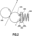
- Fig. 1 is a perspective view generally showing the configuration of an embodiment according to a liquid applying apparatus 100 of the present invention.
- the liquid applying apparatus shown in Fig. 1 roughly has liquid applying means for applying a predetermined application liquid to a medium to which a liquid is to be applied (this medium will be referred to as a applying medium in the description below) and liquid supplying means for supplying a application liquid to the liquid applying means.
- the liquid supplying means has, for example, a liquid holding member 2001 that holds the application liquid between the liquid holding member 2001 and a peripheral surface of the applying roller 1001, and a liquid channel 3000 (not shown in Fig. 1 ) described later and through which the liquid is supplied to the liquid holding member 2001.
- the applying roller 1001 and the counter roller 1002 are rotatively movably supported by respective shafts which are parallel to each other and each of which has opposite ends rotatively movably attached to a frame (not shown). Further, the liquid holding member 2001 extends almost all along the applying roller 1001 in a longitudinal direction.
- the liquid holding member 2001 is movably attached to the frame via a mechanism that enables the liquid holding member 2001 to contact with and separate from the peripheral surface of the applying roller 1001.
- the liquid applying apparatus further comprises a applying medium supplying mechanism 1006 which consists of a pickup roller or the like to convey a applying medium to a nip portion between the applying roller 1001 and the counter roller 1002.
- a sheet discharging mechanism 1007 consisting of a sheet discharging roller or the like is provided downstream of the applying roller 1001 and the counter roller 1002 to convey a applying medium on which the application liquid has been applied, to a sheet discharging section (not shown).
- the sheet supplying mechanism and the sheet discharging mechanism are operated under the driving force of the drivingmotor 1004 transmitted via the transmission mechanism 1005.
- the application liquid used in the present embodiment is intended to facilitate the coagulation of pigments when printing has been carried out using inks including the pigments as color materials.
- the application liquid is not limited to the one described above.
- a liquid including a component which insolubilizes or coagulate a dye may be used as another application liquid.
- the slidability of the abutting portion between the applying roller and the liquid holding member according to the present invention is improved by containing a component that reduces surface tension in the liquid.
- the glycerin and the surface active agent are components that reduce the surface tension.
- Fig. 2 is a vertical sectional view illustrating an example of the arrangement of the applying roller 1001, the counter roller 1002, and the liquid holding member 2001.
- the counter roller 1002 is biased by biasing means (not shown) toward the peripheral surface of the applying roller 1001.
- biasing means not shown
- the liquid holding member 2001 forms an elongate liquid holding space S extending all over an area applied the liquid by the applying roller 1001.
- the application liquid from a liquid channel 3000, described later, is supplied to the interior of the liquid holding space S via the liquid holding member 2001.
- the liquid holding member 2001 is configured as described below, the application liquid can be prevented from inadvertently leaking from the liquid holding space S to the exterior while the applying roller 1001 is stopped.
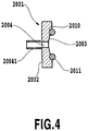
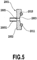
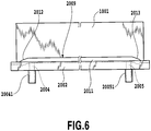
- Figs. 3 to 8 show the configuration of the liquid holding member 2001.
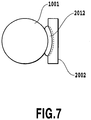
- the liquid holding member 2001 has a space forming base material 2002 and an annular abutting member 2009 located on one surface of the space forming base material 2002.
- a concave portion 2003 is formed in a central portion of the space forming base material 2002 along its longitudinal direction; a bottom portion of the concave portion 2003 has a circular cross section.
- the abutting member 2009 has linear portions fastened along the upper edges of the concave portion 2003 and circumferential portions fastened so as to extend from the upper edge through the bottom portion to the opposite upper edge.
- the abutting member 2009 formed integrally and seamlessly, is continuously abutted without a gap against the outer peripheral surface of the applying roller 1001 under the biasing force of the spring member 2006.
- the liquid holding space S is substantially closed by the abutting member 2009, one surface of the space forming base material, and the outer peripheral surface of the applying roller 1001. The liquid is held in this space.
- the abutting member 2009 and the outer peripheral surface of the applying roller 1001 maintain a liquid tight state. The liquid can be reliably prevented from leaking to the exterior.
- the applying roller 1001 when the applying roller 1001 is rotated, the application liquid can slipperily flow between the outer peripheral surface of the applying roller 1001 and the abutting member 2009 as described later.
- the abutting state of the abutting member 2009 includes not only direct abutment against the outer peripheral surface of the applying roller 1001 but also abutment against the outer peripheral surface via a liquid film formed under a capillary force.
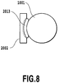
- the longitudinally opposite sides of the abutting member 2009 are gently curved as viewed from its front ( Fig. 3 ), from above ( Fig. 6 ), or from its side ( Figs. 7 and 8 ).
- the whole abutting member 2009 is substantially uniformly elastically deformed. This prevents large distortions locally.
- the abutting member 2009 abuts tightly without the gap against the outer peripheral surface of the applying roller 1001. As a result, a substantially closed space can be formed as described above.
- a liquid supplying port 2004 and a liquid collecting port 2005 are formed in an area of the space forming base material 2002 which is surrounded by the abutting member 2009; the liquid supplying port 2004 and the liquid collecting port 2005 have holes penetrating the space forming base material 2002.
- the liquid supplying port 2004 and the liquid collecting port 2005 are communicating with cylindrical connecting portions 20041 and 20051 projected from a back surface of the space forming base material. Further, the connecting portions 20041 and 20051 are connected to a liquid channel 3000 described later.
- the liquid supplying port 2004 is formed near one end of an area surrounded by the abutting member 2009 (the left end in Fig.
- Fig. 11 is a diagram generally illustrating the configuration of the liquid channel 3000, connected to the liquid holding member 2001 of the application liquid supplying means.
- the liquid channel 3000 has a first channel 3001 that connects the liquid supplying port 2004 of the space forming base member 2002, constituting the liquid holding member 2001, to a storage tank 3003 that stores the application liquid, a second channel 3002 that connects the liquid collecting port 2005 of the space forming base material 2002 to the storage tank 3003 together.
- An air communicating port 3004 is formed in the storage tank 3003.
- the air communicating port is provided with an air communicating valve 305 that selectively enables and disables the communication between the port and the air.
- the air communicating port 3004 desirably has a labyrinthine structure in order to inhibit evaporation.
- the first channel 3001 is provided with a selector valve 3006.
- the selector valve 3006 selectively enables and disables the communication between the first channel 3001 and the air. Moreover, the second channel 3002 connects to a pump 3007 used to force the application liquid and air to flow through the liquid channel 3000 in a desired direction. In this case, a flow of a liquid is generated which is directed from the first channel 3001 to the second channel 3002 via the liquid holding space S.
- the first channel 3001 and the second channel 3002 are formed of cylindrical tubes. An opening formed at an end of each tube is placed at the bottom of the storage tank 3003 or close to the bottom. The position of the opening allows the application liquid in the storage tank 3003 to be completely consumed.
- the pump 3007 is composed of a tube pump shown in Fig. 18 .
- the tube pump 3007 has a rotor 30071 rotated by a pump driving motor (not shown), a flexible pump constituting tube 30072 circularly disposed along the outside of the rotor 30071, and two rollers 30073 and 30074 rotatively movably supported by the rotor 30071.
- the rotor 30071 rotates to allow at least one of the rollers 30072 and 30074 to roll while squeezing the pump constituting tube 30072.
- This rolling drives the application liquid or air in the pump constituting tube 30072 downstream (in Fig. 18 , to the storage tank tube 30022), while sucking the application liquid or air from a liquid holding member tube 30021.
- the tube pump 3007 remains inactive while squeezing the pump constituting tube. Consequently, the communication between the tube 30021 and the tube 30022 is shut off.
- various types of the selector valves 3006 are applicable provided that they selectively enable and disable the communication between the first channel 3001 and the air.
- a three-way valve is used as shown in Fig. 11 .
- the three-way valve 3006 has three ports that are in communication with one another. It is possible to allow two of the three ports to selectively communicate with any two of the storage tank tube 3011, liquid holding member tube 3012, and air communicating port 3013 in the first channel 3001.
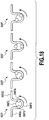
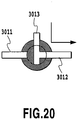
- the three-way valve 3006 allows the selective switching between a connected state in which the tubes 3011 and 3012 are in communication as shown in Fig. 19 and a connected state in which the tube 3012 and the air communicating port 3013 are in communication as shown in Fig. 20 .
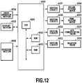
- Fig. 12 is a block diagram generally showing the configuration of the control system in the liquid applying apparatus according to the present embodiment.
- control section 4000 operates as control means for controlling the whole liquid applying apparatus.
- the control section 4000 has a CPU 4001 that performs various process operations such as calculations, control, and determinations, a ROM 4002 that stores, for example, control programs for processes executed by the CPU 4001, such as the one described later in Fig. 13 , and a RAM 4003 that temporarily stores data used during process operations of the CPU 4001 as well as input data.
- the control section 4000 connects to an input operation section 4004 including a keyboard, various switches, or the like with which predetermined instructions or data are input, a display section 4005 that provides various displays including inputs to and the set state of the liquid applying apparatus, and a detecting section 4006 including a sensor or the like which detects the position of a applying medium or the operational state of each section.
- the control section 4000 also connects to the roller driving motor 1004 , a pump driving motor 4009 , an air communicating valve 3005, and the selector valve 3006, via driving circuits 4007, 4008, 4010, and 4011.
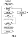
- control section 4000 executes a applying operation sequence described below, in accordance with the flowchart shown in Fig. 13 .
- step S1 the liquid holding space S is filled with the application liquid.
- the air communicating valve 3005 of the storage tank 3003 is first opened to the air.
- the selector valve (three-way valve) 3006 is also switched as shown in Fig. 19 . This allows the tubes 3011 and 3012 to communicate with each other to drive the pump 3007 for a specified time.
- air and/or the application liquid flows from the pump 3007 to the storage tank 3003. Accordingly, if the liquid holding space S and the channels 3001 and 3002 have not been filled with the application liquid, the pump drives the air inside the space and channels out to the storage tank 3003. The air is then discharged to the exterior of the apparatus. These portions are then filled with the application liquid.
- a applying start instruction is input (step S2).
- the pump 3007 restarts operation (step S3).
- the applying roller starts rotating clockwise as shown by an arrow in Fig. 1 (step S4).
- the rotation of the applying roller 1001 causes the application liquid L filled into the liquid holding space S to slipperily flow between the applying roller 1001 and a lower edge 2011 of the abutting member 2009 against the pushing force of the abutting member 2009 of the liquid holding member 2001, which force acts on the applying roller 1001.
- the application liquid adheres to the outer periphery of the applying roller 1001 in layer form.
- the application liquid L adhering to the applying roller 1001 is transferred to the abutting portion between the applying roller 1001 and the counter roller 1002.
- a applying medium supplying mechanism 1006 conveys a applying medium to between the applying roller 1001 and the counter roller 1002.
- the applying medium is inserted between these rollers and conveyed to a sheet discharging section as the applying roller 1001 and the counter roller 1002 rotate (step S5).
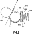
- the application liquid applied to the peripheral surface of the applying roller is transferred from the applying roller 1001 to the applying medium P as shown in Fig. 9 .
- means for supplying a applying medium to between the applying roller 1001 and the counter roller 1002 is not limited to the above supplying mechanism. It is possible to use any means, for example, manual means which uses a predetermined guide member or which is solely used.
- an area with crossing oblique lines denote the application liquid L.
- the application liquid on the applying roller 1001 and applying medium P is shown considerably thicker than the actual one in order to clearly illustrate how the application liquid L is applied.
- Fig. 9 shows the ideal applied state in which the all of the application liquid L adhering to the applying roller 1001 after slipperily flowing out of the abutting member 2009 is transferred to the applying medium P.
- the application liquid L often also adheres to and remains on the applying roller 1001.
- the amount of application liquid L remaining on the applying roller 1001 varies depending on the material of the applying medium P or the state of fine concaves and convexes on the surface of the applying medium P.
- the applying medium P is ordinary paper, the application liquid L remains on the peripheral surface of the applying roller 1001 after a applying operation.
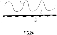
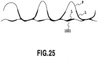
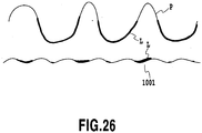
- Figs. 24 , 25 , and 26 are diagrams illustrating the process of applying between a surface of the medium P and a applying surface in the case where the medium is ordinary paper. In these figures, the liquid is painted over with black.
- Fig. 24 shows the state of the upstream side of the nip portion between the applying roller 1001 and the counter roller 1002.
- the liquid adheres to the applying surface of the applying roller 1001 so as to slightly cover the fine concaves and convexes on the applying surface.
- Fig. 25 shows the state of the surface of ordinary paper, the medium P, and the applying surface of the applying roller 1001, at the nip portion between the applying roller 1001 and the counter roller 1002.
- the convexes on the surface of the ordinary paper, the medium P contact with the applying surface of the applying roller 1001.
- the liquid instantaneously permeates through or sticks to fibers in the surface of the ordinary paper, the medium P, through the contacting parts.
- the liquid adhering to those parts of the applying surface of the applying roller which do not contact with the convex portions on the surface of the ordinary paper remains on the applying surface.
- Fig. 26 shows the state of the downstream side of the nip portion between the applying roller 1001 and the counter roller 1002.
- the medium has completely left the applying surface of the applying roller 1001.
- the liquid adhering to those parts of the applying surface of the applying roller 1001 which do not contact with the convex portions on the surface of the ordinary paper remains on the applying surface.
- the liquid on the contacting parts also remains with very small amount on the coating surface.
- the application liquid is then mixed with the application liquid filled into the space S.
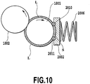
- the operation of returning the application liquid is similarly performed if the applying roller 1001 is rotated while no applying medium is present as shown in Fig. 10 . That is, the application liquid adhering to the outer periphery of the applying roller 1001 as a result of the rotation of the applying roller 1001 slipperily flows through the abutting portion between the applying roller 1001 and the counter roller 1002. After flowing through the abutting portion, the application liquid is separated into two parts directed to the applying roller 1001 and the counter roller 1002, respectively. The application liquid remains on the applying roller 1001. Then, the application liquid adhering to the applying roller 1001 slipperily flows between the upper edge 2010 of the abutting member 2009 and the applying roller 1001 to enter the liquid holding space S. The application liquid is then mixed with the application liquid filled into the space S.
- circulation of the application liquid solves the following problem: when an area of the applying roller 1001 which has finished applying the liquid to the applying medium returns to the liquid holding space S, the application liquid remaining on the applying roller 1001 without being applied is disadvantageously mixed into the application liquid in the liquid holding space S, together with bubbles.
- This also solves the following problem: evaporation that may occur even in the liquid-tight liquid holding space S disadvantageously increases the concentration of the application liquid.
- the apparatus determines whether or not to finish the applying step. If the applying step is not to be finished, the process returns to step S5 to repeat the applying operation until the applying step is executed on the all the parts of the applying medium to which the liquid needs to be applied.
- the applying roller 1001 is stopped (step S7).
- the driving of the pump 3007 is stopped (step S8).
- the process shifts to step S2 to repeat the operations from step S2 to step S8 unless an applying start instruction is input before a predetermined period elapses. Even after the predetermined period has elapsed, if the applying start instruction is not input, a postprocess is executed such as a collecting operation of collecting the application liquid from the liquid holding space S and liquid channels (step S9). Then, the coating process is finished.
- step S8 the pump 3007 may not be stopped. In this case, after stopping the applying roller 1001 in step S7, the process proceeds to step S2.
- step S9 the process of collecting the application liquid held by the liquid holding member 2001 is executed in step S9.
- the collecting process executed in step S9 will be described below in detail with reference to Fig. 21 .
- Fig. 21 is a flowchart showing a process procedure for collecting a liquid in the liquid applying apparatus according to the present embodiment.
- step S2 in Fig. 13 when the apparatus determines that the applying start instruction has not been input, the apparatus starts an operation of collecting the application liquid held in the liquid holding member 2001.
- step S21 the pump 3007 is driven in step S21 in Fig. 21 to generate a flow from the pump 3007 to the storage tank 3003.
- step S8 the present step is not executed. Instead, when the application liquid collecting operation is started, the process proceeds to step S22.
- step S22 the selector valve (three-way valve) 3006 is switched as shown in Fig. 20 .
- the air communicating port 3013 is thus allowed to communicate with the tube 3012. That is, the supply path from the storage tank 3003 to the liquid holding member 2001 is shut off to inhibit the supply of the application liquid to the liquid holding member 2001.
- the pump 3007 is creating a flow in the direction of an arrow in Fig. 11 , so that the application liquid present in the channel from the liquid holding tube 3012 to the second channel 3002, including the liquid holding member 2001, is collected in the storage tank 3003. Further, they are filled with air from the air communicating port 3013.
- step S23 the driving of the pump 3003 is stopped. Then, the storage tank tube 30022 is shut off from the liquid holding member tube 30021. Further, the tube 3011 is shut off from the tube 3012 by the selector valve 3006.
- the pump 3007 may be stopped after a predetermined time is elapse after the switching of the selector valve 3006 in step S22.
- the liquid holding member 2001 may contain means for sensing a timing for stopping the pump 3007 , for example, a sensor serving as means for sensing whether or not any application liquid remains in the liquid holding member 2001. Then, the pump 3003 may be stopped on the basis of sensed information.
- step S24 the air communicating port 3004 is closed. In this state, the storage tank 3003 is shut off from the air.
- the selector valve 3006 is placed upstream of the pump 3007.
- the pump 3007 may be placed on a supply path (in this case, the first channel 3001), whereas the selector valve 3006 may be placed on a collecting path (in this case, the second channel 3002).
- the selector valve 3006 is switched to allow the air communicating port 3013 to communicate with the liquid holding member side of the second channel 3002.
- the storage tank side of the second channel 3002 is shut off from its liquid holding member side.
- the pump 3007 is reversely driven, that is, the rotation of the rotor 30071 of the pump 3007 is reversed to create a flow in the direction opposite to that of an arrow in Fig. 11 .
- This allows the application liquid in the liquid holding member 2001 and channels to be collected and collected in the storage tank 3003.
- the pump is stopped (step S23).
- the air communicating port 3004 in the storage tank is closed (step S24).
- the reverse driving of the pump 3007 may be started before, after, or simultaneously with the switching of the selector valve 3006.
- the pump 3007 used in the present embodiment has a function for shutting off the channels while not being driven.
- the check valve may be placed on the channel on which the pump 3007 is placed.
- Te check valve may be placed on the storage tank 3003 side or the liquid holding member 2001 side with respect to the pump.
- the check calve is placed on the storage tank 3003 side.
- the application liquid can be collected from the channels containing the liquid holding member to the storage tank by switching the selector valve having the air communicating port and driving the pump.
- the collecting makes it possible to reduce evaporation that may occur when the application liquid is left in the liquid holding member for a long time.
- the selector valve and the pump or on-off valve placed in the channel are used to shut off the application liquid channels.
- the air communicating port formed in the storage tank is also shut off from the air. Consequently, even if the application liquid flows out of the storage tank, it can be prevented from reaching the liquid holding member. Therefore, even if the apparatus is tilted during transportation or storage, no application liquid is present in the liquid holding member at that time. Naturally enough, no water head occurs, thus inhibiting the leakage of the liquid from the liquid holding member.
- the present embodiment is the applying apparatus described in the first embodiment wherein an on-off valve is used in place of the selector valve (three-way valve) 3006 to collect the liquid from the liquid holding space if the applying operation is not performed, the liquid holding space being formed between the applying roller and the liquid holding member to hold the liquid.
- an on-off valve is used in place of the selector valve (three-way valve) 3006 to collect the liquid from the liquid holding space if the applying operation is not performed, the liquid holding space being formed between the applying roller and the liquid holding member to hold the liquid.
- Fig. 22 is a diagram generally illustrating the configuration of the liquid channel connected to the liquid holding member according to the present invention.
- a first on-off valve 6001 and a second on-off valve 6002 are located in place of the selector valve (three-way valve) 3006 shown in Fig. 11 .
- the first channel 3001 has an air communicating port 6003.
- the second on-off valve 6002 is provided on the air communication port 6003.
- the first on-off valve 6001 is provided between the air communicating port 6003 and the storage tank 3003. The combination of open and closed states of the first and second on-off valves enables the selective switching between a connected state in which the tubes 3011 and 3012 are in communication and a connected state in which the air communicating port 6003 and the tube 3012 are in communication.
- This switching makes it possible to selectively supply the application liquid or air in the storage tank 3003 to the liquid holding space S formed by the liquid holding member 2001 and the applying roller 1001.
- Each of the first and second on-off valves 6001 and 6002 is opened and closed in accordance with a control signal from the control section 4000, shown in Fig. 12 .
- the application liquid is thus filled or supplied.
- a process procedure for applying a liquid in the liquid applying apparatus is the same as that shown in Fig. 13 except for steps S1 and S9. Accordingly, the description of the other steps is omitted. A detailed description will be given of steps S1 and S9 according to the present embodiment.
- step S1 a step of filling the application liquid into the liquid holding space S is executed.
- the air communicating valve 3005 in the storage tank 3003 is opened to the air.
- the second on-off valve 6002 is closed, while the first on-off valve 6001 is opened, thus allowing the tubes 3011 and 3012 to communicate with each other.
- the pump 3007 is then driven for a specified time. This produces the same effect as that produced by the switching operation of the selector valve (three-way valve) 3006.
- the application liquid is thus filled into the liquid holding member 2001 and channels as descried in step S1 in Fig. 13 .
- step S9 a process for collecting the application liquid held in the liquid holding member 2001 is executed in accordance with the process procedure shown in Fig. 21 .
- a process procedure for collecting a liquid is the same as that shown in Fig. 21 except for step S22. Accordingly, the description of the other steps is omitted. A detailed description will be given of step S22 according to the present embodiment.
- step S22 the second on-off valve 6002 is opened at the same time when the first on-off valve 6001 is closed.
- This allows the air communicating port 6003 to communicate with the tube 3012. That is, the supply path from the storage tank 3003 to the liquid holding member 2001 is shut off by closing the first on-off valve 6001.
- the pump 3007 is creating a flow in the direction of an arrow shown in Fig. 22 . Consequently, the application liquid in the channels containing the liquid holding member 2001 is collected in the storage tank 3003.
- air from the air communicating port 6003 enters and fills the liquid holding member 2001 and the channels.
- the first on-off valve 6001 may be closed before the second on-off valve 6002 is opened.
- steps S23 and S24 are executed to finish the operation of collecting the application liquid. Then, the storage tank 3003 is shut off from the air.
- the application liquid can be collected from the channels including the liquid holding member to the storage tank, as in the first embodiment.
- the collecting makes it possible to reduce evaporation that may occur when the application liquid is left in the liquid holding member for a long time.
- the application liquid when the collecting of the application liquid is finished, the application liquid can be prevented from flowing out of the storage tank and reaching the liquid holding member. Therefore, even if the apparatus is tilted during transportation or storage, or the liquid holding member is separated from the applying roller or the pressure under which the liquid holding member is abutted against the applying roller is reduced when the collecting is finished, the liquid is prevented from leaking from the liquid holding member.
- the water head in a part of the channel connecting the storage tank and the liquid holding member together is set higher than the highest level in the storage tank.
- the liquid is selectively supplied to and collected from the liquid holding member by selectively enabling and disabling the communication between the high water head and the air.
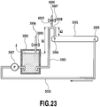
- Fig. 23 is a diagram generally showing the configuration of a application liquid channel according to the present embodiment.
- Fig. 23 for the configurations of the coating apparatus, liquid holding member, and liquid channel, parts similar to those in the second embodiment are denoted by the same reference numerals.
- the liquid holding member (liquid holding means) 2001 and the storage tank (storage means) 3003 are also connected together via the first channel 3001 and second channel 3002.
- the pump 3007 is connected to the second channel 2002.
- the first channel 3001 connects to an air introducing path 6005 at a connecting portion 6008, the path 6005 having an air communicating port 6006 at its upper end.
- the air introducing path 6005 is provided with an on-off valve 6007 that selectively enables and disables the communication between the air communicating port 6006 and the connecting portion 6008.
- the water head in the connecting portion 6008 is set higher (above in a gravitational direction) than the (highest) level (for example, f in the figure) in the storage tank 3003.
- h1 denotes a difference in water head between the level f and the connecting portion.
- the air communicating valve 3005 in the storage tank 3003 is opened, while the on-off valve 6007 in the air introducing path 6005 is closed.
- the pump 3007 is then driven. This operation enables the application liquid in the storage tank 3003 to flow in the direction of an arrow in the figure. The liquid can thus be supplied to the interior of the liquid holding member 2001. Further, when the application liquid is to be collected, the pump 3007 is driven, while the on-off valve 6007 is opened.
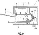
- Fig. 14 is a diagram generally showing the configuration of an ink jet printing apparatus 1 comprising a applying mechanism having almost the same configuration as that of the above liquid applying apparatus.
- Fig. 16 is a block diagram showing a control arrangement for the above ink jet printing apparatus.
- the roller driving motor 1004, the pump driving motor 4009 , and the actuator 3005 for the air communicating valve, all of which are elements of the liquid applying mechanism, are similar to those descried for the liquid applying apparatus.
- a CPU 5001 controls the driving of the elements of the applying mechanism.
- the CPU 5001 also controls the driving of an LF motor 5013, a CR motor 5015, and the print head 7 which relate to the printing mechanism, via driving circuits 5012 and 5014 and a head driver 5016. That is, driving by the LF motor 5013 rotates the conveying roller 4. Driving by the CR motor moves a carriage on which the print head 7 is mounted.
- the CPU 5001 performs control such that inks are ejected through the nozzles in the print head.
- Fig. 17 is a flowchart showing the procedure of liquid application and an accompanying printing operation in the ink jet printing apparatus according to the present embodiment.
- the processing during steps S101, during S103 to S105, and during S108 to S110 is similar to that during step S1, during steps S3 to S5, and during steps S7 to S9, all the steps being shown in Fig. 13 .
- a print start instruction is given (step S102).
- a series of liquid applying operations such as pump activation are performed (steps S103 to S105).
- a printing operation is performed on a print medium having the application liquid applied to desired parts of the medium (step S106). That is, the print head 7 is scanned over the print medium P conveyed by the conveying roller 4 by a predetermined amount at a time. During the scan, inks are ejected from the nozzles in accordance with print data so as to adhere to the print medium to form dots. The adhering inks react with the application liquid, thus improving the concentration and preventing bleeding. The conveyance of the print medium and the scanning of the print head are repeated to print the print medium P. The finished print medium is discharged onto the sheet discharging tray 10.
- the applying mechanism applies the liquid to another part of the print medium. Every time the print medium is conveyed by a predetermined amount, liquid application and printing are sequentially executed on different parts of the print medium.
- printing may be carried out after one print medium has been completely applied the application liquid to as described in Japanese Patent Application Laid-open No. 2002-096452 .
- step S107 determines in step S107 that the printing has been finished
- step S108 and the subsequent steps is executed to finish the present process.
- the liquid is applied in the ink jet printing-based printing apparatus.
- the present invention is applicable to printing apparatuses based on other systems.
- the degree of whiteness of the medium can be improved by using a liquid containing a fluorescent whitening agent as a application liquid.
- a liquid containing components to restrain a curl (phenomenon in which a medium becomes curve shape) of the application medium may be used.
- the printing means after the liquid application is not limited to the ink jet printing system. Effects can be produced using a printing system such as a thermal transfer system or an electrophotographic system.
- a photosensitive agent as the application liquid may be applied before printing.
- the apparatus may determine in step S2 in Fig. 13 or in step S102 in Fig. 17 that the applying start instruction has not been input. Then, before the process proceeds to step S9 in Fig. 13 or step S110 in Fig. 17 , the apparatus may determine whether or not a predetermined time has elapsed since the start of a standby mode of the liquid applying apparatus or ink jet printing apparatus.
- step S9 in Fig. 13 or step S110 in Fig. 117 determines whether or not the applying start instruction has been input. If the apparatus determines that the predetermined time has elapsed since the start of the standby mode, it proceeds to step S9 in Fig. 13 or step S110 in Fig. 117 to execute the corresponding postprocess. If the apparatus determines that the predetermined time has not elapsed since the start of the standby mode, it proceeds to step S2 in Fig. 13 or step S102 in Fig. 117 to determine whether or not the applying start instruction has been input.
Landscapes
- Coating Apparatus (AREA)
- Ink Jet (AREA)
- Application Of Or Painting With Fluid Materials (AREA)
Claims (18)
- Flüssigkeitsauftragsgerät (100), das Folgendes aufweist:eine Flüssigkeitsauftragseinrichtung (1001, 1002, 1003), die mit einem Auftragsbauteil (1001), das angepasst ist, um eine Flüssigkeit auf ein Medium (P) aufzutragen, und einem Haltebauteil (2001) zum Ausbilden eines Flüssigkeitshalteraums (S) vorgesehen ist, um die Flüssigkeit zu halten, zum Auftragen der Flüssigkeit, die in dem Flüssigkeitshalteraum (S) gehalten wird, auf das Medium (P) durch das Auftragsbauteil (1001) durch Drehen des Auftragsbauteils (1001);eine Speichereinrichtung (3003) zum Speichern der Flüssigkeit;einen ersten Pfad (3001), der angepasst ist, um zu ermöglichen, dass die Speichereinrichtung (3003) und das Haltebauteil (2001) miteinander in Verbindung stehen;einen zweiten Pfad (3002), der angepasst ist, um zu ermöglichen, dass die Speichereinrichtung (3003) und das Haltebauteil (2001) miteinander in Verbindung stehen; undeine Sammeleinrichtung zum Ermöglichen, dass der erste (3001) oder der zweite Pfad (3002) mit der Luft in Verbindung stehen, um eine Strömung der Flüssigkeit in einem Kanal einschließlich des ersten Pfads (3001), des Flüssigkeitshalteraums (S) und des zweiten Pfads (3002) zu erzeugen, so dass die Strömung die Flüssigkeit von dem Kanal zu der Speichereinrichtung (3003) sammelt,dadurch gekennzeichnet, dassdas Haltebauteil (2001) ein Raumausbildungsbasismaterial (2002) und ein ringförmiges Anlagebauteil (2009) hat, wobei das ringförmige Anlagebauteil (2009) an dem Raumausbildungsbasismaterial (2002) befestigt ist und einstückig und nahtlos ausgebildet ist und an dem Auftragsbauteil (1001) derart anliegt, dass das Anliegen mit der Form der Umfangsfläche des Auftragsbauteils (1001) übereinstimmt und dass der Flüssigkeitshalteraum (S) durch das Anlagebauteil (2009), eine Fläche des Raumausbildungsbasismaterials (2002) und die Außenumfangsfläche des Auftragsbauteils (1001) geschlossen ist, und wobei aus Sicht von vorne (Fig. 3), von oben (Fig. 6) und von der Seite (Figuren 7 und 8) längsverlaufende gegenüberliegende Seiten des ringförmigen Anlagebauteils (2009) sanft gebogen sind, derart, dass das ganze ringförmige Anlagebauteil (2009) gleichmäßig elastisch verformt wird, wenn das ringförmige Anlagebauteil (2009) an dem Auftragsbauteil (1001) anliegt, undwobei ein Flüssigkeitszufuhranschluss (2004), der mit dem ersten Pfad (3001) verbunden ist, nahe einem gebogenen Teil des Anlagebauteils (2009) ausgebildet ist, wohingegen ein Flüssigkeitssammelanschluss (2005), der mit dem zweiten Pfad (3002) verbunden ist, nahe dem anderen gebogenen Teil des Anlagebauteils (2009) ausgebildet ist.
- Flüssigkeitsauftragsgerät (100) nach Anspruch 1, wobei die Sammeleinrichtung Folgendes aufweist:eine Umschalteinrichtung (3006) zum Umschalten, ob entweder die Speichereinrichtung (3003) und das Haltebauteil (2001) miteinander in Verbindung stehen oder die Luft und das Haltebauteil (2001) miteinander über den ersten (3001) oder den zweiten Pfad (3002) in Verbindung stehen; undeine Flüssigkeitsbewegungseinrichtung (3007) zum Erzeugen einer Strömung der Flüssigkeit in dem Flüssigkeitspfad einschließlich des ersten Pfads (3001), des Flüssigkeitshalteraums (S) und des zweiten Pfads (3002), undwobei die Umschalteinrichtung (3006) umschaltbar ist, um zu ermöglichen, dass die Luft und das Haltebauteil (2001) miteinander in Verbindung stehen, und die Flüssigkeitsbewegungseinrichtung (3007) bewirkt, dass die Flüssigkeit von dem ersten Pfad (3001) zu dem zweiten Pfad (3002) oder von dem zweiten Pfad (3002) zu dem ersten Pfad (3001) strömt, um die Flüssigkeit von dem Haltebauteil (2001) zu der Speichereinrichtung (3003) zu sammeln.
- Flüssigkeitsauftragsgerät (100) nach Anspruch 2, wobei die Flüssigkeitsbewegungseinrichtung (3007) stromabwärtig der Umschalteinrichtung (3006) angeordnet ist, wenn der Halteraum (S) mit der Flüssigkeit von der Speichereinrichtung (3003) gefüllt wird, und ferner in dem ersten (3001) oder dem zweiten Pfad (3002) angeordnet ist.
- Flüssigkeitsauftragsgerät (100) nach Anspruch 3, wobei die Flüssigkeitsbewegungseinrichtung (3007) in dem ersten Pfad (3001) angeordnet ist und eine Einrichtung zum Verhindern, dass die Flüssigkeit zurückströmt, des Weiteren in dem zweiten Pfad (3002) angeordnet ist.
- Flüssigkeitsauftragsgerät (100) nach Anspruch 2 oder 3, wobei die Umschalteinrichtung (3006) in dem ersten Pfad (3001) angeordnet ist und die Flüssigkeitsbewegungseinrichtung (3007) in dem zweiten Pfad (3002) angeordnet ist, wobei, wenn die Flüssigkeit von dem Halteraum (S) zu der Speichereinrichtung (3003) durch den zweiten Pfad (3002) gesammelt wird, die Flüssigkeitsbewegungseinrichtung (3007) in der Lage ist, die Flüssigkeit von dem ersten Pfad (3001) zu dem zweiten Pfad (3002) zu bewegen.
- Flüssigkeitsauftragsgerät (100) nach einem der Ansprüche 2 bis 5, wobei, wenn ein Antreiben der Flüssigkeitsbewegungseinrichtung (3007) gestoppt wird, die Flüssigkeitsbewegungseinrichtung (3007) angepasst ist, um den Kanal für die Flüssigkeit, in dem die Flüssigkeitsbewegungseinrichtung (3007) angeordnet ist, abzusperren.
- Flüssigkeitsauftragsgerät (100) nach einem der Ansprüche 1 bis 6, wobei die Speichereinrichtung eine Luftverbindungseinrichtung (3005) zum wahlweisen Öffnen und Schließen eines Luftverbindungsanschlusses (3004) aufweist, der angepasst ist, um zu ermöglichen, dass die Speichereinrichtung (3003) und die Luft miteinander in Verbindung stehen, und die Luftverbindungseinrichtung (3005) angepasst ist, um den Luftverbindungsanschluss (3004) zu schließen, wenn das Sammeln abgeschlossen ist.
- Flüssigkeitsauftragsgerät (100) nach einem der Ansprüche 2 bis 7, wobei die Flüssigkeitsbewegungseinrichtung (3007) in der Lage ist, die Flüssigkeit von dem ersten Pfad (3001) zu dem zweiten Pfad (3002) zu bewegen, um die Flüssigkeit zwischen der Speichereinrichtung (3003) und dem Haltebauteil (2001) zirkulieren zu lassen.
- Flüssigkeitsauftragsgerät (100) nach Anspruch 1, wobei zumindest ein Teil des ersten Pfads (3001) so angeordnet ist, dass eine Position einer Wassersäule in dem ersten Pfad (3001) höher ist als ein höchstes Speicherniveau, das ein Niveau ist, das beobachtet wird, wenn die größte Menge an Flüssigkeit in der Speichereinrichtung (3003) gespeichert ist, unddie Sammeleinrichtung ermöglicht, dass zumindest ein Teil des ersten Pfads (3001), der in der Wassersäulenposition angeordnet ist, mit der Luft in Verbindung steht.
- Flüssigkeitsauftragsgerät (100) nach Anspruch 2,wobei die Umschalteinrichtung (3006) in dem ersten Pfad (3001) angeordnet ist und die Flüssigkeitsbewegungseinrichtung (3007) stromabwärtig der Umschalteinrichtung (3007) in dem ersten (3001) oder dem zweiten Pfad (3002) angeordnet ist.
- Flüssigkeitsauftragsgerät (100) nach Anspruch 2, wobeidie Sammeleinrichtung angepasst ist, um die Flüssigkeit von dem Kanal zu der Speichereinrichtung (3003) mittels der Umschalteinrichtung (3006), um zu ermöglichen, dass die Luft und das Haltebauteil (2001) miteinander in Verbindung stehen, und mittels der Flüssigkeitsbewegungseinrichtung (3007) zu sammeln, um eine Strömung der Flüssigkeit zu erzeugen,die Umschalteinrichtung (3006) stromaufwärtig in einer Richtung einer Strömung der Flüssigkeit, die auftritt, wenn die Sammeleinrichtung die Flüssigkeit sammelt, verglichen zu dem Haltebauteil (2001) angeordnet ist, unddie Flüssigkeitsbewegungseinrichtung (3007) stromabwärtig in der Richtung der Strömung der Flüssigkeit, die auftritt, wenn die Sammeleinrichtung die Flüssigkeit sammelt, verglichen zu der Umschalteinrichtung (3006) angeordnet ist.
- Flüssigkeitsauftragsgerät (100) nach Anspruch 2, wobeider erste Pfad (3001) zumindest teilweise so angeordnet ist, dass eine Wassersäule in dem ersten Pfad (3001) höher ist als ein höchstes Speicherniveau, das ein Niveau ist, das beobachtet wird, wenn die größte Menge an Flüssigkeit in der Speichereinrichtung (3003) gespeichert ist;die Umschalteinrichtung (3006) zum Umschalten dient, um entweder einen Teil des ersten Pfads (3001), der in einer Position der Wassersäule liegt, die höher ist als das höchste Speicherniveau, mit der Luft in Verbindung zu setzen oder von der Luft abzusperren;die Sammeleinrichtung angepasst ist, um die Flüssigkeit von dem Kanal zu der Speichereinrichtung (3003) mittels der Umschalteinrichtung (3006), um zu ermöglichen, dass die Luft und das Haltebauteil (2001) miteinander in Verbindung stehen, und mittels der Flüssigkeitsbewegungseinrichtung (3007) zu sammeln, um eine Strömung der Flüssigkeit zu erzeugen, wobei die Umschalteinrichtung (3006) stromaufwärtig in einer Richtung einer Strömung der Flüssigkeit, die auftritt, wenn die Sammeleinrichtung die Flüssigkeit sammelt, verglichen zu dem Haltebauteil (2001) angeordnet ist, unddie Flüssigkeitsbewegungseinrichtung (3007) stromabwärtig in der Richtung der Strömung der Flüssigkeit, die auftritt, wenn die Sammeleinrichtung die Flüssigkeit sammelt, verglichen zu der Umschalteinrichtung (3006) angeordnet ist.
- Tintenstrahldruckgerät (1), das Folgendes aufweist:das Flüssigkeitsauftragsgerät (100) nach einem der vorangegangenen Ansprüche; undeine Bilderzeugungseinrichtung zum Erzeugen eines Bilds, bevorzugt durch Ausstoßen von Tinten aus einem Druckkopf (7), in dem eine Vielzahl von Düsen angeordnet sind, auf dem Medium (P), auf das die Flüssigkeit durch die Flüssigkeitsauftragseinrichtung (1001, 1002, 1003) aufgetragen worden ist.
- Verfahren zum Steuern eines Flüssigkeitsauftragsgeräts (100), das Folgendes aufweist:einen Schritt zum Vorbereiten des Flüssigkeitsauftragsgeräts (100), das ein Auftragsbauteil (1001), das angepasst ist, um eine Flüssigkeit auf ein Medium (P) aufzutragen, und ein Haltebauteil (2001) aufweist, das ein Raumausbildungsbasismaterial (2002) und ein ringförmiges Anlagebauteil (2009) hat, wobei das ringförmige Anlagebauteil (2009) an dem Raumausbildungsbasismaterial (2002) befestigt ist und einstückig und nahtlos ausgebildet ist und an dem Auftragsbauteil (1001) derart anliegt, dass das Anliegen mit der Form der Umfangsfläche des Auftragsbauteils (1001) übereinstimmt und dass ein Flüssigkeitshalteraum (S) durch das Anlagebauteil (2009), eine Fläche des Raumausbildungsbasismaterials (2002) und die Außenumfangsfläche des Auftragsbauteils (1001) geschlossen ist, und wobei aus Sicht von vorne (Fig. 3), von oben (Fig. 6) und von der Seite (Figuren 7 und 8) längsverlaufende gegenüberliegende Seiten des ringförmigen Anlagebauteils (2009) sanft gebogen sind, derart, dass das ganze ringförmige Anlagebauteil (2009) gleichmäßig elastisch verformt wird, wenn das ringförmige Anlagebauteil (2009) an dem Auftragsbauteil (1001) anliegt, um den Flüssigkeitshalteraum (S) zum Halten der Flüssigkeit auszubilden, wobei das Gerät (100) die Flüssigkeit, die in dem Flüssigkeitshalteraum (S) gehalten wird, auf das Medium (P) durch das Auftragsbauteil (1001) durch Drehen des Auftragsbauteils (1001) aufträgt,einen Schritt zum Ermöglichen, dass ein erster (3001) oder ein zweiter Pfad (3002) mit der Luft in Verbindung stehen, wobei der erste (3001) oder der zweite Pfad (3002) ermöglicht, dass eine Speichereinrichtung (3003) zum Speichern der Flüssigkeit und das Haltebauteil (2001) miteinander in Verbindung stehen, und zum Erzeugen einer Strömung der Flüssigkeit in einem Kanal einschließlich des ersten Pfads (3001), des Flüssigkeitshalteraums (S) und des zweiten Pfads (3002), so dass die Strömung die Flüssigkeit von dem Kanal zu der Speichereinrichtung (3003) sammelt, wobei ein Flüssigkeitszufuhranschluss (2004), der mit dem ersten Pfad (3001) verbunden ist, nahe einem gebogenen Teil des Anlagebauteils (2009) ausgebildet ist, wohingegen ein Flüssigkeitssammelanschluss (2005), der mit dem zweiten Pfad (3002) verbunden ist, nahe dem anderen gebogenen Teil des Anlagebauteils (2009) ausgebildet ist.
- Flüssigkeitsauftragssteuerungsverfahren nach Anspruch 14, das des Weiteren einen Schritt, wenn der Sammelschritt einmal abgeschlossen ist, zum Schließen eines Luftverbindungsanschlusses (3004) aufweist, der vor dem Sammelprozess geöffnet wird und der ermöglicht, dass die Speichereinrichtung (3003) und die Luft miteinander in Verbindung stehen.
- Flüssigkeitsauftragssteuerungsverfahren nach Anspruch 14 oder 15, wobei in dem Sammelschritt eine Flüssigkeitsbewegungseinrichtung (3007) zum Erzeugen einer Strömung der Flüssigkeit das Sammeln ausführt.
- Flüssigkeitsauftragssteuerungsverfahren nach Anspruch 16, wobei, wenn die Flüssigkeitsbewegungseinrichtung (3007) gestoppt wird, die Flüssigkeitsbewegungseinrichtung (3007) den Kanal für die Flüssigkeit, in dem die Flüssigkeitsbewegungseinrichtung (3007) angeordnet ist, absperrt.
- Flüssigkeitsauftragssteuerungsverfahren nach einem der Ansprüche 14 bis 17, wobei während des Beschichtens der Flüssigkeit die Flüssigkeit zwischen der Speichereinrichtung (3003) und dem Haltebauteil (2001) zirkuliert.
Applications Claiming Priority (2)
| Application Number | Priority Date | Filing Date | Title |
|---|---|---|---|
| JP2004035805 | 2004-02-12 | ||
| JP2004035805 | 2004-02-12 |
Publications (3)
| Publication Number | Publication Date |
|---|---|
| EP1564010A2 EP1564010A2 (de) | 2005-08-17 |
| EP1564010A3 EP1564010A3 (de) | 2010-05-26 |
| EP1564010B1 true EP1564010B1 (de) | 2017-04-12 |
Family
ID=34697912
Family Applications (1)
| Application Number | Title | Priority Date | Filing Date |
|---|---|---|---|
| EP05002780.4A Expired - Lifetime EP1564010B1 (de) | 2004-02-12 | 2005-02-10 | Vorrichtung zum Auftragen von Flüssigkeit und Farbstrahldruckgerät |
Country Status (3)
| Country | Link |
|---|---|
| US (1) | US7270409B2 (de) |
| EP (1) | EP1564010B1 (de) |
| CN (1) | CN100368199C (de) |
Families Citing this family (23)
| Publication number | Priority date | Publication date | Assignee | Title |
|---|---|---|---|---|
| JP4498148B2 (ja) * | 2004-02-12 | 2010-07-07 | キヤノン株式会社 | 液体塗布装置、記録装置 |
| US7556339B2 (en) * | 2004-02-12 | 2009-07-07 | Canon Kabushiki Kaisha | Ink jet printing apparatus |
| JP4355586B2 (ja) * | 2004-02-12 | 2009-11-04 | キヤノン株式会社 | 液体塗布装置およびインクジェット記録装置 |
| DE602006012896D1 (de) * | 2005-04-28 | 2010-04-29 | Brother Ind Ltd | Tintenstrahlaufzeichnungsapparat und Steuerung desselben |
| JP4480166B2 (ja) * | 2005-08-11 | 2010-06-16 | キヤノン株式会社 | 液体塗布装置およびインクジェット記録装置 |
| JP5116471B2 (ja) | 2005-08-15 | 2013-01-09 | キヤノン株式会社 | 液体塗布装置およびインクジェット記録装置 |
| JP2007099834A (ja) * | 2005-09-30 | 2007-04-19 | Fujifilm Corp | インク組成物、インクセット及びインクジェット画像記録方法 |
| CN101121323B (zh) * | 2006-08-09 | 2012-06-20 | 鸿富锦精密工业(深圳)有限公司 | 喷墨系统及维持喷墨头与墨池之间压力差恒定的方法 |
| US8726834B2 (en) | 2006-12-11 | 2014-05-20 | Canon Kabushiki Kaisha | Liquid applying apparatus and ink jet printing apparatus |
| JP5241003B2 (ja) * | 2008-09-05 | 2013-07-17 | 富士フイルム株式会社 | 液体塗布装置及び方法並びに画像形成装置 |
| JP5148440B2 (ja) * | 2008-09-29 | 2013-02-20 | 富士フイルム株式会社 | 液体塗布装置、液体貯蔵方法及びインクジェット記録装置 |
| US20100154706A1 (en) * | 2008-12-19 | 2010-06-24 | Canon Kabushiki Kaisha | Liquid applying apparatus |
| DE102009007590A1 (de) * | 2009-02-05 | 2010-09-09 | Hauni Maschinenbau Ag | Beleimung von Materialstreifen der Tabak verarbeitenden Industrie |
| KR20110006322A (ko) * | 2009-07-14 | 2011-01-20 | 삼성전자주식회사 | 화상형성장치 |
| KR101695333B1 (ko) * | 2009-11-13 | 2017-01-12 | 주식회사 탑 엔지니어링 | 액정 공급장치 및 액정 공급 및 회수방법 |
| JP5464492B2 (ja) * | 2010-06-16 | 2014-04-09 | 株式会社リコー | 画像形成装置及び処理液付与装置 |
| JP6222965B2 (ja) | 2012-05-07 | 2017-11-01 | キヤノン株式会社 | 記録装置及び記録装置の制御方法 |
| JP2013252697A (ja) | 2012-05-08 | 2013-12-19 | Canon Inc | 記録装置及び記録装置の制御方法 |
| US8840230B2 (en) * | 2012-06-04 | 2014-09-23 | Xerox Corporation | Ink waste tray configured with one way filter |
| JP6068271B2 (ja) * | 2013-06-10 | 2017-01-25 | 東レ株式会社 | 塗布器、及び塗布装置 |
| JP6884991B2 (ja) * | 2016-05-26 | 2021-06-09 | セイコーエプソン株式会社 | 液体供給弁および流路システム並びに液体供給弁の使用方法 |
| JP7289423B2 (ja) | 2017-09-29 | 2023-06-12 | キヤノン株式会社 | 液体吐出装置および液体吐出ヘッド |
| CN115415103B (zh) * | 2022-09-14 | 2024-05-24 | 汕头市鼎泰丰实业有限公司 | 一种纺织面料表面处理用智能化涂布设备及涂布工艺 |
Citations (1)
| Publication number | Priority date | Publication date | Assignee | Title |
|---|---|---|---|---|
| US5080013A (en) * | 1989-03-25 | 1992-01-14 | Man Roland Druckmaschinen Ag | Chambered doctor blade system for printing machine inkers |
Family Cites Families (20)
| Publication number | Priority date | Publication date | Assignee | Title |
|---|---|---|---|---|
| FR2182403A5 (de) * | 1972-04-27 | 1973-12-07 | Air Ind | |
| DE2835413A1 (de) * | 1978-08-12 | 1980-02-21 | Hoechst Ag | Einrichtung zur elektrischen standueberwachung einer entwicklerloesung in einem vorratsgefaess |
| DE3203087A1 (de) * | 1982-01-30 | 1983-08-04 | Gebrüder Sucker, 4050 Mönchengladbach | Verfahren und vorrichtung zum beschichten oder imraegnieren eines bahnfoermig gefuehrten substrates |
| US4949667A (en) * | 1988-04-20 | 1990-08-21 | Dainippon Screen Mfg. Co., Ltd. | Roll coating apparatus for forming a film of a high viscosity coating liquid on a surface |
| US5132706A (en) * | 1989-04-12 | 1992-07-21 | Canon Kabushiki Kaisha | Transferring ink with an adhesive characteristic changed by applied voltage and replacing component loss of ink in response to determined changes of ink |
| US5045888A (en) * | 1989-05-30 | 1991-09-03 | Brother Kogyo Kabushiki Kaisha | Image fixing device and method for fixing image |
| US5056036A (en) * | 1989-10-20 | 1991-10-08 | Pulsafeeder, Inc. | Computer controlled metering pump |
| US5207159A (en) * | 1991-08-30 | 1993-05-04 | Howard W. DeMoore | Coating apparatus for sheet-fed, offset rotary printing presses |
| US5367982A (en) * | 1993-02-25 | 1994-11-29 | Howard W. DeMoore | Automatic coating circulation and wash-up system for printing presses |
| JP3184050B2 (ja) | 1994-08-24 | 2001-07-09 | 富士機械工業株式会社 | グラビア印刷機のインク供給装置 |
| JPH0872227A (ja) | 1994-09-02 | 1996-03-19 | Canon Inc | 画像形成装置 |
| US5960713A (en) * | 1995-05-04 | 1999-10-05 | Howard W. DeMoore | Retractable printing-coating unit operable on the plate and blanket cylinders simultaneously from the dampener side of the first printing unit or any consecutive printing unit or any rotary offset printing press |
| JP3640369B2 (ja) * | 1997-09-04 | 2005-04-20 | 株式会社リコー | 画像記録法及び画像記録装置並びに画像記録促進液 |
| US6183079B1 (en) * | 1998-06-11 | 2001-02-06 | Lexmark International, Inc. | Coating apparatus for use in an ink jet printer |
| US7105203B1 (en) * | 1999-02-10 | 2006-09-12 | Mastsushita Electric Industrial Co., Ltd. | Intermittent coating apparatus and intermittent coating method |
| JP2001070858A (ja) | 1999-07-07 | 2001-03-21 | Canon Inc | 塗料の塗工装置および塗工方法 |
| US6383296B1 (en) * | 1999-11-22 | 2002-05-07 | Harris & Bruno Machine Co. | Chambered doctor blade with automatic cleanup and ink replacement |
| JP4025004B2 (ja) | 2000-09-22 | 2007-12-19 | 株式会社リコー | 画像記録装置 |
| US6585364B2 (en) * | 2001-05-29 | 2003-07-01 | Hewlett-Packard Development Company, L.P. | Methods and apparatus for improving inkjet print quality |
| US6706118B2 (en) * | 2002-02-26 | 2004-03-16 | Lexmark International, Inc. | Apparatus and method of using motion control to improve coatweight uniformity in intermittent coaters in an inkjet printer |
-
2005
- 2005-02-07 CN CNB200510008252XA patent/CN100368199C/zh not_active Expired - Fee Related
- 2005-02-08 US US11/052,023 patent/US7270409B2/en not_active Expired - Fee Related
- 2005-02-10 EP EP05002780.4A patent/EP1564010B1/de not_active Expired - Lifetime
Patent Citations (1)
| Publication number | Priority date | Publication date | Assignee | Title |
|---|---|---|---|---|
| US5080013A (en) * | 1989-03-25 | 1992-01-14 | Man Roland Druckmaschinen Ag | Chambered doctor blade system for printing machine inkers |
Also Published As
| Publication number | Publication date |
|---|---|
| CN1654207A (zh) | 2005-08-17 |
| EP1564010A2 (de) | 2005-08-17 |
| US7270409B2 (en) | 2007-09-18 |
| CN100368199C (zh) | 2008-02-13 |
| EP1564010A3 (de) | 2010-05-26 |
| US20050200666A1 (en) | 2005-09-15 |
Similar Documents
| Publication | Publication Date | Title |
|---|---|---|
| EP1564010B1 (de) | Vorrichtung zum Auftragen von Flüssigkeit und Farbstrahldruckgerät | |
| US8038268B2 (en) | Liquid applying apparatus and ink jet printing apparatus | |
| US8087744B2 (en) | Ink jet printing apparatus | |
| US7588639B2 (en) | Liquid applying apparatus and ink jet printing apparatus | |
| EP1563996B1 (de) | Tintenstrahldruckvorrichtung | |
| EP2082810B1 (de) | Flüssigkeitsauftragsvorrichtung und Druckvorrichtung | |
| US7537661B2 (en) | Liquid applying apparatus and ink-jet printing apparatus | |
| JP4669347B2 (ja) | 液体塗布装置およびインクジェット記録装置 | |
| US20070070163A1 (en) | Liquid application device, inkjet recording apparatus, and method of controlling liquid application device | |
| US20070101936A1 (en) | Liquid applying apparatus and ink-jet printing apparatus | |
| US8001921B2 (en) | Liquid application device and inkjet recording apparatus | |
| JP4677246B2 (ja) | インクジェット記録装置 | |
| US7536974B2 (en) | Liquid applying apparatus and printing apparatus | |
| JP4748768B2 (ja) | インクジェット記録装置 | |
| JP4508978B2 (ja) | 液体塗布装置およびインクジェット記録装置 | |
| JP4355662B2 (ja) | インクジェット記録装置 |
Legal Events
| Date | Code | Title | Description |
|---|---|---|---|
| PUAI | Public reference made under article 153(3) epc to a published international application that has entered the european phase |
Free format text: ORIGINAL CODE: 0009012 |
|
| AK | Designated contracting states |
Kind code of ref document: A2 Designated state(s): AT BE BG CH CY CZ DE DK EE ES FI FR GB GR HU IE IS IT LI LT LU MC NL PL PT RO SE SI SK TR |
|
| AX | Request for extension of the european patent |
Extension state: AL BA HR LV MK YU |
|
| PUAL | Search report despatched |
Free format text: ORIGINAL CODE: 0009013 |
|
| 17P | Request for examination filed |
Effective date: 20051017 |
|
| AK | Designated contracting states |
Kind code of ref document: A3 Designated state(s): AT BE BG CH CY CZ DE DK EE ES FI FR GB GR HU IE IS IT LI LT LU MC NL PL PT RO SE SI SK TR |
|
| AX | Request for extension of the european patent |
Extension state: AL BA HR LV MK YU |
|
| RIC1 | Information provided on ipc code assigned before grant |
Ipc: B41J 11/00 20060101AFI20050525BHEP Ipc: B05C 1/08 20060101ALI20100420BHEP Ipc: B05C 11/10 20060101ALI20100420BHEP |
|
| 17Q | First examination report despatched |
Effective date: 20101105 |
|
| AKX | Designation fees paid |
Designated state(s): DE FR GB IT |
|
| GRAP | Despatch of communication of intention to grant a patent |
Free format text: ORIGINAL CODE: EPIDOSNIGR1 |
|
| INTG | Intention to grant announced |
Effective date: 20160913 |
|
| GRAJ | Information related to disapproval of communication of intention to grant by the applicant or resumption of examination proceedings by the epo deleted |
Free format text: ORIGINAL CODE: EPIDOSDIGR1 |
|
| GRAP | Despatch of communication of intention to grant a patent |
Free format text: ORIGINAL CODE: EPIDOSNIGR1 |
|
| GRAS | Grant fee paid |
Free format text: ORIGINAL CODE: EPIDOSNIGR3 |
|
| INTC | Intention to grant announced (deleted) | ||
| GRAA | (expected) grant |
Free format text: ORIGINAL CODE: 0009210 |
|
| INTG | Intention to grant announced |
Effective date: 20170215 |
|
| AK | Designated contracting states |
Kind code of ref document: B1 Designated state(s): DE FR GB IT |
|
| REG | Reference to a national code |
Ref country code: GB Ref legal event code: FG4D |
|
| REG | Reference to a national code |
Ref country code: DE Ref legal event code: R096 Ref document number: 602005051710 Country of ref document: DE |
|
| REG | Reference to a national code |
Ref country code: DE Ref legal event code: R097 Ref document number: 602005051710 Country of ref document: DE |
|
| PLBE | No opposition filed within time limit |
Free format text: ORIGINAL CODE: 0009261 |
|
| STAA | Information on the status of an ep patent application or granted ep patent |
Free format text: STATUS: NO OPPOSITION FILED WITHIN TIME LIMIT |
|
| PG25 | Lapsed in a contracting state [announced via postgrant information from national office to epo] |
Ref country code: IT Free format text: LAPSE BECAUSE OF FAILURE TO SUBMIT A TRANSLATION OF THE DESCRIPTION OR TO PAY THE FEE WITHIN THE PRESCRIBED TIME-LIMIT Effective date: 20170412 |
|
| 26N | No opposition filed |
Effective date: 20180115 |
|
| REG | Reference to a national code |
Ref country code: DE Ref legal event code: R119 Ref document number: 602005051710 Country of ref document: DE |
|
| GBPC | Gb: european patent ceased through non-payment of renewal fee |
Effective date: 20180210 |
|
| REG | Reference to a national code |
Ref country code: FR Ref legal event code: ST Effective date: 20181031 |
|
| PG25 | Lapsed in a contracting state [announced via postgrant information from national office to epo] |
Ref country code: DE Free format text: LAPSE BECAUSE OF NON-PAYMENT OF DUE FEES Effective date: 20180901 |
|
| PG25 | Lapsed in a contracting state [announced via postgrant information from national office to epo] |
Ref country code: GB Free format text: LAPSE BECAUSE OF NON-PAYMENT OF DUE FEES Effective date: 20180210 Ref country code: FR Free format text: LAPSE BECAUSE OF NON-PAYMENT OF DUE FEES Effective date: 20180228 |