US7270409B2 - Liquid applying apparatus and ink jet printing apparatus - Google Patents
Liquid applying apparatus and ink jet printing apparatus Download PDFInfo
- Publication number
- US7270409B2 US7270409B2 US11/052,023 US5202305A US7270409B2 US 7270409 B2 US7270409 B2 US 7270409B2 US 5202305 A US5202305 A US 5202305A US 7270409 B2 US7270409 B2 US 7270409B2
- Authority
- US
- United States
- Prior art keywords
- liquid
- applying
- path
- holding member
- medium
- Prior art date
- Legal status (The legal status is an assumption and is not a legal conclusion. Google has not performed a legal analysis and makes no representation as to the accuracy of the status listed.)
- Expired - Fee Related, expires
Links
Images


Classifications
-
- B—PERFORMING OPERATIONS; TRANSPORTING
- B41—PRINTING; LINING MACHINES; TYPEWRITERS; STAMPS
- B41J—TYPEWRITERS; SELECTIVE PRINTING MECHANISMS, i.e. MECHANISMS PRINTING OTHERWISE THAN FROM A FORME; CORRECTION OF TYPOGRAPHICAL ERRORS
- B41J2/00—Typewriters or selective printing mechanisms characterised by the printing or marking process for which they are designed
- B41J2/005—Typewriters or selective printing mechanisms characterised by the printing or marking process for which they are designed characterised by bringing liquid or particles selectively into contact with a printing material
- B41J2/01—Ink jet
- B41J2/17—Ink jet characterised by ink handling
- B41J2/175—Ink supply systems ; Circuit parts therefor
- B41J2/17596—Ink pumps, ink valves
-
- B—PERFORMING OPERATIONS; TRANSPORTING
- B41—PRINTING; LINING MACHINES; TYPEWRITERS; STAMPS
- B41J—TYPEWRITERS; SELECTIVE PRINTING MECHANISMS, i.e. MECHANISMS PRINTING OTHERWISE THAN FROM A FORME; CORRECTION OF TYPOGRAPHICAL ERRORS
- B41J11/00—Devices or arrangements of selective printing mechanisms, e.g. ink-jet printers or thermal printers, for supporting or handling copy material in sheet or web form
- B41J11/0015—Devices or arrangements of selective printing mechanisms, e.g. ink-jet printers or thermal printers, for supporting or handling copy material in sheet or web form for treating before, during or after printing or for uniform coating or laminating the copy material before or after printing
-
- B—PERFORMING OPERATIONS; TRANSPORTING
- B41—PRINTING; LINING MACHINES; TYPEWRITERS; STAMPS
- B41J—TYPEWRITERS; SELECTIVE PRINTING MECHANISMS, i.e. MECHANISMS PRINTING OTHERWISE THAN FROM A FORME; CORRECTION OF TYPOGRAPHICAL ERRORS
- B41J2/00—Typewriters or selective printing mechanisms characterised by the printing or marking process for which they are designed
- B41J2/005—Typewriters or selective printing mechanisms characterised by the printing or marking process for which they are designed characterised by bringing liquid or particles selectively into contact with a printing material
- B41J2/01—Ink jet
- B41J2/17—Ink jet characterised by ink handling
- B41J2/175—Ink supply systems ; Circuit parts therefor
- B41J2/17503—Ink cartridges
- B41J2/17506—Refilling of the cartridge
- B41J2/17509—Whilst mounted in the printer
-
- B—PERFORMING OPERATIONS; TRANSPORTING
- B41—PRINTING; LINING MACHINES; TYPEWRITERS; STAMPS
- B41J—TYPEWRITERS; SELECTIVE PRINTING MECHANISMS, i.e. MECHANISMS PRINTING OTHERWISE THAN FROM A FORME; CORRECTION OF TYPOGRAPHICAL ERRORS
- B41J29/00—Details of, or accessories for, typewriters or selective printing mechanisms not otherwise provided for
-
- B—PERFORMING OPERATIONS; TRANSPORTING
- B05—SPRAYING OR ATOMISING IN GENERAL; APPLYING FLUENT MATERIALS TO SURFACES, IN GENERAL
- B05C—APPARATUS FOR APPLYING FLUENT MATERIALS TO SURFACES, IN GENERAL
- B05C1/00—Apparatus in which liquid or other fluent material is applied to the surface of the work by contact with a member carrying the liquid or other fluent material, e.g. a porous member loaded with a liquid to be applied as a coating
- B05C1/04—Apparatus in which liquid or other fluent material is applied to the surface of the work by contact with a member carrying the liquid or other fluent material, e.g. a porous member loaded with a liquid to be applied as a coating for applying liquid or other fluent material to work of indefinite length
- B05C1/08—Apparatus in which liquid or other fluent material is applied to the surface of the work by contact with a member carrying the liquid or other fluent material, e.g. a porous member loaded with a liquid to be applied as a coating for applying liquid or other fluent material to work of indefinite length using a roller or other rotating member which contacts the work along a generating line
- B05C1/0813—Apparatus in which liquid or other fluent material is applied to the surface of the work by contact with a member carrying the liquid or other fluent material, e.g. a porous member loaded with a liquid to be applied as a coating for applying liquid or other fluent material to work of indefinite length using a roller or other rotating member which contacts the work along a generating line characterised by means for supplying liquid or other fluent material to the roller
Definitions
- the present invention relates to a liquid applying apparatus and an ink jet printing apparatus, and specifically, to a liquid applying apparatus that applies a liquid to a medium for a predetermined purpose, for example, for starting the coagulation of pigments earlier when printing is carried out using inks composed of the pigments as color materials.
- a liquid applying apparatus that applies a liquid to a medium for a predetermined purpose, for example, for starting the coagulation of pigments earlier when printing is carried out using inks composed of the pigments as color materials.
- an ink jet printing apparatus comprising a mechanism that applies the liquid to a print medium used for ink jet printing, for a predetermined purpose, for example, for starting the coagulation of pigments earlier when printing is carried out using inks composed of the pigments as color materials.
- a spin coater, a roll coater, a bar coater, and a die coater are known as systems for applying a liquid or an aqueous material to various media. These applying systems are premised on continuous applying on relatively long applying media. Thus, for example, if liquid is applied to applying media having a relatively small size and being intermittently conveyed, paint beads may be disturbed at a position at which the applying is started or ended. In this case, the coats obtained may be nonuniform among the applying media.
- Japanese Patent Application Laid-open No. 2002-517341 describes an apparatus which uses a doctor blade contacting with a roller and in which the application liquid is collected between the blade and the roller so that the application liquid is applied to the roller as the roller rotates. As the roller rotates, the application liquid applied to the roller is transferred and applied to a support conveyed between this roller and another roller.
- Japanese Patent Application Laid-open No. 08-072227 similarly discloses a mechanism in an ink jet printing apparatus which applies a treatment liquid before printing which liquid insolubilizes dyes.
- the treatment liquid in a replenishing tank is pumped by being attached to the rotating roller. At the same time, the treatment liquid pumped is applied to print paper.
- an application liquid is applied or supplied to the surface of the rod bar or roller.
- the part of the rod bar or roller to which the application liquid is applied or supplied is open to or in communication with the air.
- the application liquid may be evaporated or for example, the application liquid may leak when the posture of the apparatus is changed.
- Japanese Patent Application Laid-open No. 08-058069 discloses a configuration that seals a part that applies or supplies inks, that is, application liquids, to a roller.
- the applying mechanism described in this document operates in a gravure printing apparatus to apply inks to a roller (applying roller) whose surface is formed with a pattern of a printing plate.
- This mechanism uses an ink chamber having two doctor blades arranged at two vertical positions along a peripheral surface of the roller and extending in a longitudinal direction of the roller and elastic members provided at the opposite sides of the two doctor blades.
- the chamber is contacted with the peripheral surface of the roller to form a liquid chamber between the ink chamber and the roller.
- the roller is rotated to apply or supply the application liquid from the liquid chamber to the roller.
- the applying roller when the applying operation is not performed, if the applying roller remains in contact with or immersed in the applying liquid in the liquid chamber for a long time, then the applying liquid may degrade the applying roller.
- the applying liquid may leak from the liquid chamber as a result of a change in the posture of the liquid applying apparatus such as a tilt. That is, if the liquid applying mechanism has a long structure, then in a normal applying posture, a longitudinal direction of the liquid applying mechanism corresponds to a horizontal direction. If the longitudinal direction of the liquid applying mechanism is changed so as to correspond to a vertical direction, a large difference occurs in water head between the upper side and lower side in the vertical direction, corresponding to the longitudinal direction. Pressure resulting from the difference in water head may cause the leakage of the liquid on the lower side in the vertical direction.
- the leakage of the liquid may occur if a difference occurs in the water head between the upper side and lower side after the tilt. Therefore, the posture of the liquid applying apparatus during transportation or storage is limited. The liquid may leak from the liquid chamber unless the posture is carefully maintained.
- the present invention is made to solve the above problems. It is an object of the present invention to provide a liquid applying apparatus and an ink jet printing apparatus which can reduce the evaporation of the application liquid when left in a liquid holding member for a long time, the liquid holding member holding the application liquid in a space between rollers, the liquid applying apparatus and ink jet printing apparatus being capable of preventing the leakage of the liquid from the liquid holding member.
- a liquid applying apparatus comprising:
- a liquid applying means which is provided with an applying member that applies a liquid to a medium and a holding member that abuts against the applying member to form a liquid holding space to hold the liquid, for applying the liquid held in the liquid holding space to the medium through the applying member by rotating the applying member;
- a collecting means for allowing the first or second path to communicate with the air to generate a flow of the liquid in a channel including the first path, the liquid holding space and the second path so that the flow collects the liquid from the channel to the storage means.
- a liquid applying apparatus comprising:
- a liquid applying means which is provided with an applying member that applies a liquid to a medium and a holding member that abuts against the applying member to form a liquid holding space to hold the liquid, for applying the liquid held in the liquid holding space to the medium through the applying member by rotating the applying member;
- switching means for switching whether the storage means and the holding member are communicate with each other or the air and the holding member are communicated with each other for the first path
- a liquid moving means for generating a flow of the liquid in a liquid path including the first path, the liquid holding space, and the second path, and
- a liquid applying apparatus comprising:
- a liquid applying means which is provided with an applying member that applies a liquid to a medium and a holding member that abuts against the applying member to form a liquid holding space to hold the liquid, for applying the liquid held in the liquid holding space to the medium through the applying member by rotating the applying member;
- first and second paths that allow the storage means and the holding member to communicate with each other
- switching means for switching whether the storage means and the holding member communicate with each other or the air and the holding member are communicated with each other for the first path;
- a liquid moving means for generating a flow of the liquid in a liquid path including the first path, the liquid holding space, and the second path, and
- switching means is placed upstream in a direction of a flow of the liquid which occurs when the collecting means collects the liquid, compared to the holding member, and
- a liquid applying apparatus comprising:
- a liquid applying means which is provided with an applying member that applies a liquid to a medium and a holding member that abuts against the applying member to form a liquid holding space to hold the liquid, for applying the liquid held in the liquid holding space to the medium through the applying member by rotating the applying member;
- a first path which allows the storage means and the holding means to communicate with each other and which is at least partly placed so that a water head in the first path is higher than a highest storage level that is a level observed when the largest amount of liquid is stored in the storage means;
- switching means for switching whether a part of the first path which is at a position of the water head higher than the highest storage level is to communicate with the air or to be shut off from the air;
- liquid moving means for generating a flow of the liquid in a liquid path including the first path, the liquid holding space, and the second path;
- switching means is placed upstream in a direction of a flow of the liquid which occurs when the collecting means collects the liquid, compared to the holding member, and
- an ink jet printing apparatus comprising:
- a liquid applying means which is provided with an applying member that applies a liquid to a medium and a holding member that abuts against the applying member to form a liquid holding space to hold the liquid, for applying liquid held in the liquid holding space to the medium through the applying member by rotating the applying member;
- an image forming means for forming an image by ejecting inks from a print head in which a plurality of nozzles are arranged on the medium to which the liquid has been applied by the liquid applying means;
- a collecting means for allowing the first or second path to communicate with the air to generate a flow of the liquid in a channel including the first path, the liquid holding space and the second path so that the flow collects the liquid from the channel to the storage means.
- a printing apparatus comprising:
- a liquid applying means which is provided with an applying member that applies a liquid to a medium and a holding member that abuts against the applying member to form a liquid holding space to hold the liquid, for applying the liquid held in the liquid holding space to the medium through the applying member by rotating the applying member;
- an image forming means for forming an image on the medium to which the liquid has been applied by the liquid applying means
- a collecting means for allowing the first or second path to communicate with the air to generate a flow of the liquid in a channel including the first path, the liquid holding space and the second path so that the flow collects the liquid from the channel to the storage means.
- a liquid applying apparatus comprising:
- a step of preparing the liquid applying apparatus comprising an applying member that applies a liquid to a medium and a holding member that abuts against the applying member to form a liquid holding space to hold the liquid, the apparatus applying the liquid held in the liquid holding space to the medium through the applying member by rotating the applying member,
- a step of allowing a first or second path to communicate with the air the first or second path allowing a storage means for storing the liquid and the holding means to communicate with each other, and generating a flow of the liquid in a channel including the first path, the liquid holding space and the second path so that the flow collects the liquid from the channel to the storage means.
- the “liquid moving means” according to the present invention may be a pump.
- the switching means carries out switching to allow the air and the holding member to communicate with each other so that the pump can be used to allow the liquid to flow from the supply path to the collection path or vice versa. Accordingly, the liquid from the holding member can be collected in the storage means. This makes it possible to reduce the evaporation of the liquid when left in the holding member for a long time.
- the storage means is shut off from the air to inhibit the liquid from flowing out of the storage means to the holding means. If the posture of the liquid applying apparatus is changed, the leakage of the liquid from the holding member can be prevented.
- FIG. 1 is a perspective view generally showing the configuration of an embodiment according to a liquid applying apparatus of the present invention
- FIG. 2 is a vertical side view showing an example of the arrangement of a applying roller, a counter roller, and a liquid holding member which are shown in FIG. 1 ;
- FIG. 3 is a front view of the liquid holding member shown in FIGS. 1 and 2 ;
- FIG. 4 is an end view showing an end surface of the liquid holding member shown in FIG. 3 , the view taken along line IV-IV in FIG. 3 ;
- FIG. 5 is an end view showing the end surface of the liquid holding member shown in FIG. 3 , the view taken along line V-V in FIG. 3 ;
- FIG. 6 is a plan view of the liquid holding member shown in FIG. 3 ;
- FIG. 7 is a left side view showing how an abutting portion of the liquid holding member shown in FIG. 3 is abutted against a liquid applying roller;
- FIG. 8 is a right side view showing how the abutting portion of the liquid holding member shown in FIG. 3 is abutted against the liquid applying roller;
- FIG. 9 is a vertical sectional view showing how a application liquid is filled into a liquid holding space formed by the liquid holding member and the applying roller and how a liquid is applied to an applying medium by the rotation of the applying roller;
- FIG. 10 is a vertical sectional view showing how the application liquid is filled into the liquid holding space formed by the liquid holding member and the applying roller and how the applying roller is rotated when no applying medium is present;
- FIG. 11 is a diagram generally showing the configuration of a liquid channel in the liquid applying apparatus according to the embodiment of the present invention.
- FIG. 12 is a block diagram generally showing the configuration of a control system according to the embodiment of the present invention.
- FIG. 13 is a flowchart showing a liquid applying operation sequence according to the embodiment of the present invention.
- FIG. 14 is a vertical side view generally showing the configuration of an ink jet printing apparatus according to the embodiment of the present invention.
- FIG. 15 is a perspective view showing how a printing section and the liquid applying apparatus are arranged if the ink jet printing apparatus according to the embodiment in FIG. 14 is configured as a serial printer type;
- FIG. 16 is a block diagram generally showing the configuration of a control system of the ink jet printing apparatus according to the present invention.
- FIG. 17 is a flowchart showing the sequences of an applying operation and a printing operation according to another embodiment of the present invention.
- FIG. 18 is a diagram illustrating operations of a pump according to the embodiment of the present invention.
- FIG. 19 is a diagram illustrating a three-way valve according to the embodiment of the present invention.
- FIG. 20 is a diagram illustrating the three-way valve according to the embodiment of the present invention.
- FIG. 21 is a flowchart showing the procedure of a postprocess in the flowchart shown in FIG. 13 ;
- FIG. 22 is a diagram generally showing the configuration of a liquid channel in a liquid applying apparatus according to a second embodiment of the present invention.
- FIG. 23 is a diagram generally showing the configuration of a liquid channel in a liquid applying apparatus according to a third embodiment of the present invention.
- FIG. 24 is a diagram illustrating an applying process executed on a surface of a medium P and a applying surface if the medium is ordinary paper;
- FIG. 25 is a diagram illustrating the applying process executed on the surface of the medium P and the applying surface if the medium is ordinary paper.
- FIG. 26 is a diagram illustrating the applying process executed on the surface of the medium P and the applying surface if the medium is ordinary paper.
- a liquid is collected from a liquid holding space formed between an applying roller and a liquid holding member to hold the liquid.
- FIG. 1 is a perspective view generally showing the configuration of an embodiment according to a liquid applying apparatus 100 of the present invention.
- the liquid applying apparatus shown in FIG. 1 roughly has liquid applying means for applying a predetermined application liquid to a medium to which a liquid is to be applied (this medium will be referred to as an applying medium in the description below) and liquid supplying means for supplying an application liquid to the liquid applying means.
- the liquid applying means has a cylindrical applying roller 1001 , a cylindrical counter roller 1002 (medium supporting member) placed opposite the applying roller 1001 , and a roller driving mechanism 1003 that drives the applying roller 1001 .
- the roller driving mechanism 1003 comprises a roller driving motor 1004 and a transmission mechanism 1005 which transmits the driving force of the roller driving motor 1004 to the applying roller 1001 and which has a gear train and the like.
- the liquid supplying means has, for example, a liquid holding member 2001 that holds the application liquid between the liquid holding member 2001 and a peripheral surface of the applying roller 1001 , and a liquid channel 3000 (not shown in FIG. 1 ) described later and through which the liquid is supplied to the liquid holding member 2001 .
- the applying roller 1001 and the counter roller 1002 are rotatively movably supported by respective shafts which are parallel to each other and each of which has opposite ends rotatively movably attached to a frame (not shown). Further, the liquid holding member 2001 extends almost all along the applying roller 1001 in a longitudinal direction.
- the liquid holding member 2001 is movably attached to the frame via a mechanism that enables the liquid holding member 2001 to contact with and separate from the peripheral surface of the applying roller 1001 .
- the liquid applying apparatus further comprises an applying medium supplying mechanism 1006 which consists of a pickup roller or the like to convey a applying medium to a nip portion between the applying roller 1001 and the counter roller 1002 .
- an applying medium supplying mechanism 1006 which consists of a pickup roller or the like to convey a applying medium to a nip portion between the applying roller 1001 and the counter roller 1002 .
- a sheet discharging mechanism 1007 consisting of a sheet discharging roller or the like is provided downstream of the applying roller 1001 and the counter roller 1002 to convey an applying medium on which the application liquid has been applied, to a sheet discharging section (not shown).
- the sheet supplying mechanism and the sheet discharging mechanism are operated under the driving force of the driving motor 1004 transmitted via the transmission mechanism 1005 .
- the application liquid used in the present embodiment is intended to facilitate the coagulation of pigments when printing has been carried out using inks including the pigments as color materials.
- the application liquid has a viscosity of 5 to 6 cp (centipoise) at 25° C.
- the application liquid is not limited to the one described above.
- a liquid including a component which insolubilizes or coagulates a dye may be used as another application liquid.
- the slidability of the abutting portion between the applying roller and the liquid holding member according to the present invention is improved by containing a component that reduces surface tension in the liquid.
- the glycerin and the surface active agent are components that reduce the surface tension.
- FIG. 2 is a vertical sectional view illustrating an example of the arrangement of the applying roller 1001 , the counter roller 1002 , and the liquid holding member 2001 .
- the counter roller 1002 is biased by biasing means (not shown) toward the peripheral surface of the applying roller 1001 .
- biasing means not shown
- the liquid holding member 2001 forms an elongate liquid holding space S extending all over an area applied the liquid by the applying roller 1001 .
- the application liquid from a liquid channel 3000 described later, is supplied to the interior of the liquid holding space S via the liquid holding member 2001 .
- the liquid holding member 2001 is configured as described below, the application liquid can be prevented from inadvertently leaking from the liquid holding space S to the exterior while the applying roller 1001 is stopped.
- FIGS. 3 to 8 show the configuration of the liquid holding member 2001 .
- the liquid holding member 2001 has a space forming base material 2002 and an annular abutting member 2009 located on one surface of the space forming base material 2002 .
- a concave portion 2003 is formed in a central portion of the space forming base material 2002 along its longitudinal direction; a bottom portion of the concave portion 2003 has a circular cross section.
- the abutting member 2009 has linear portions fastened along the upper edges of the concave portion 2003 and circumferential portions fastened so as to extend from the upper edge through the bottom portion to the opposite upper edge.
- the abutting member 2009 formed integrally and seamlessly, is continuously abutted without a gap against the outer peripheral surface of the applying roller 1001 under the biasing force of the spring member 2006 .
- the liquid holding space S is substantially closed by the abutting member 2009 , one surface of the space forming base material, and the outer peripheral surface of the applying roller 1001 .
- the liquid is held in this space.
- the abutting member 2009 and the outer peripheral surface of the applying roller 1001 maintain a liquid tight state. The liquid can be reliably prevented from leaking to the exterior.
- the applying roller 1001 when the applying roller 1001 is rotated, the application liquid can slipperily flow between the outer peripheral surface of the applying roller 1001 and the abutting member 2009 as described later.
- the abutting state of the abutting member 2009 includes not only direct abutment against the outer peripheral surface of the applying roller 1001 but also abutment against the outer peripheral surface via a liquid film formed under a capillary force.
- the longitudinally opposite sides of the abutting member 2009 are gently curved as viewed from its front ( FIG. 3 ), from above ( FIG. 6 ), or from its side ( FIGS. 7 and 8 ).
- the whole abutting member 2009 is substantially uniformly elastically deformed. This prevents large distortions locally.
- the abutting member 2009 abuts tightly without the gap against the outer peripheral surface of the applying roller 1001 .
- a substantially closed space can be formed as described above.
- a liquid supplying port 2004 and a liquid collecting port 2005 are formed in an area of the space forming base material 2002 which is surrounded by the abutting member 2009 ; the liquid supplying port 2004 and the liquid collecting port 2005 have holes penetrating the space forming base material 2002 .
- the liquid supplying port 2004 and the liquid collecting port 2005 are communicating with cylindrical connecting portions 20041 and 20051 projected from a back surface of the space forming base material. Further, the connecting portions 20041 and 20051 are connected to a liquid channel 3000 described later.
- the liquid supplying port 2004 is formed near one end of an area surrounded by the abutting member 2009 (the left end in FIG.
- the liquid supplying port 2004 is used to supply the application liquid provided through the liquid channel 3000 , to the liquid holding space S.
- the liquid collecting port 2005 is used to allow the liquid in the liquid holding space S to flow out to the liquid channel 3000 .
- the supply and flowout of the application liquid allows the liquid to flow from the left end to right end of the liquid holding space S.
- FIG. 11 is a diagram generally illustrating the configuration of the liquid channel 3000 , connected to the liquid holding member 2001 of the application liquid supplying means.
- the liquid channel 3000 has a first channel 3001 that connects the liquid supplying port 2004 of the space forming base member 2002 , constituting the liquid holding member 2001 , to a storage tank 3003 that stores the application liquid, a second channel 3002 that connects the liquid collecting port 2005 of the space forming base material 2002 to the storage tank 3003 together.
- An air communicating port 3004 is formed in the storage tank 3003 .
- the air communicating port is provided with an air communicating valve 305 that selectively enables and disables the communication between the port and the air.
- the air communicating port 3004 desirably has a labyrinthine structure in order to inhibit evaporation.
- the first channel 3001 is provided with a selector valve 3006 .
- the selector valve 3006 selectively enables and disables the communication between the first channel 3001 and the air. Moreover, the second channel 3002 connects to a pump 3007 used to force the application liquid and air to flow through the liquid channel 3000 in a desired direction. In this case, a flow of a liquid is generated which is directed from the first channel 3001 to the second channel 3002 via the liquid holding space S.
- the first channel 3001 and the second channel 3002 are formed of cylindrical tubes. An opening formed at an end of each tube is placed at the bottom of the storage tank 3003 or close to the bottom. The position of the opening allows the application liquid in the storage tank 3003 to be completely consumed.
- the pump 3007 is composed of a tube pump shown in FIG. 18 .
- the tube pump 3007 has a rotor 30071 rotated by a pump driving motor (not shown), a flexible pump constituting tube 30072 circularly disposed along the outside of the rotor 30071 , and two rollers 30073 and 30074 rotatively movably supported by the rotor 30071 .
- the rotor 30071 rotates to allow at least one of the rollers 30073 and 30074 to roll while squeezing the pump constituting tube 30072 . This rolling drives the application liquid or air in the pump constituting tube 30072 downstream (in FIG.
- various types of the selector valves 3006 are applicable provided that they selectively enable and disable the communication between the first channel 3001 and the air.
- a three-way valve is used as shown in FIG. 11 .
- the three-way valve 3006 has three ports that are in communication with one another. It is possible to allow two of the three ports to selectively communicate with any two of the storage tank tube 3011 , liquid holding member tube 3012 , and air communicating port 3013 in the first channel 3001 .
- the three-way valve 3006 allows the selective switching between a connected state in which the tubes 3011 and 3012 are in communication as shown in FIG. 19 and a connected state in which the tube 3012 and the air communicating port 3013 are in communication as shown in FIG. 20 .
- the application liquid in the storage tank 3003 or air obtained through the air communicating port 3013 to be selectively supplied to the space S formed by the liquid holding member 2001 and the applying roller 1001 .
- the tubes 3011 and 3012 are in communication as shown in FIG. 19
- the application liquid in the storage tank 3003 is supplied to the liquid holding space S.
- the tube 3012 and the air communicating port 3013 are in communication as shown in FIG. 20
- the air obtained through the air communicating port 3013 is supplied to the liquid holding space S.
- the switching of the three-way valve 3006 is carried out in accordance with a control signal from a control section 4000 described later.
- the application liquid is filled or supplied.
- FIG. 12 is a block diagram generally showing the configuration of the control system in the liquid applying apparatus according to the present embodiment.
- control section 4000 operates as control means for controlling the whole liquid applying apparatus.
- the control section 4000 has a CPU 4001 that performs various process operations such as calculations, control, and determinations, a ROM 4002 that stores, for example, control programs for processes executed by the CPU 4001 , such as the one described later in FIG. 13 , and a RAM 4003 that temporarily stores data used during process operations of the CPU 4001 as well as input data.
- the control section 4000 connects to an input operation section 4004 including a keyboard, various switches, or the like with which predetermined instructions or data are input, a display section 4005 that provides various displays including inputs to and the set state of the liquid applying apparatus, and a detecting section 4006 including a sensor or the like which detects the position of a applying medium or the operational state of each section.
- the control section 4000 also connects to the roller driving motor 1004 , a pump driving motor 4009 , an air communicating valve 3005 , and the selector valve 3006 , via driving circuits 4007 , 4008 , 4010 , and 4011 .
- FIG. 13 is a flowchart showing a process procedure for applying a liquid in the liquid applying apparatus according to the present embodiment. The steps of liquid application will be described below with reference to this flowchart.
- control section 4000 executes an applying operation sequence described below, in accordance with the flowchart shown in FIG. 13 .
- step S 1 the liquid holding space S is filled with the application liquid.
- the air communicating valve 3005 of the storage tank 3003 is first opened to the air.
- the selector valve (three-way valve) 3006 is also switched as shown in FIG. 19 . This allows the tubes 3011 and 3012 to communicate with each other to drive the pump 3007 for a specified time.
- air and/or the application liquid flows from the pump 3007 to the storage tank 3003 .
- the pump drives the air inside the space and channels out to the storage tank 3003 .
- the air is then discharged to the exterior of the apparatus. These portions are then filled with the application liquid.
- an applying start instruction is input (step S 2 ).
- the pump 3007 restarts operation (step S 3 ).
- the applying roller starts rotating clockwise as shown by an arrow in FIG. 1 (step S 4 ).
- the rotation of the applying roller 1001 causes the application liquid L filled into the liquid holding space S to slipperily flow between the applying roller 1001 and a lower edge 2011 of the abutting member 2009 against the pushing force of the abutting member 2009 of the liquid holding member 2001 , which force acts on the applying roller 1001 .
- the application liquid adheres to the outer periphery of the applying roller 1001 in layer form.
- the application liquid L adhering to the applying roller 1001 is transferred to the abutting portion between the applying roller 1001 and the counter roller 1002 .
- an applying medium supplying mechanism 1006 conveys an applying medium between the applying roller 1001 and the counter roller 1002 .
- the applying medium is inserted between these rollers and conveyed to a sheet discharging section as the applying roller 1001 and the counter roller 1002 rotate (step S 5 ).
- the application liquid applied to the peripheral surface of the applying roller is transferred from the applying roller 1001 to the applying medium P as shown in FIG. 9 .
- means for supplying an applying medium between the applying roller 1001 and the counter roller 1002 is not limited to the above supplying mechanism. It is possible to use any means, for example, manual means which uses a predetermined guide member or which is solely used.
- an area with crossing oblique lines denotes the application liquid L.
- the application liquid on the applying roller 1001 and applying medium P is shown considerably thicker than the actual one in order to clearly illustrate how the application liquid L is applied.
- an applied part of the applying medium P is conveyed in the direction of the arrow under the conveying force of the applying roller 1001 . Further, an unapplied part of the applying medium P is conveyed to the contact portion between the applying medium P and the applying roller 1001 . This operation is continuously or intermittently performed to apply the application liquid to the entire applying medium.
- FIG. 9 shows the ideal applied state in which the all of the application liquid L adhering to the applying roller 1001 after slipperily flowing out of the abutting member 2009 is transferred to the applying medium P.
- the application liquid L often also adheres to and remains on the applying roller 1001 .
- the amount of application liquid L remaining on the applying roller 1001 varies depending on the material of the applying medium P or the state of fine concaves and convexes on the surface of the applying medium P.
- the applying medium P is ordinary paper, the application liquid L remains on the peripheral surface of the applying roller 1001 after an applying operation.
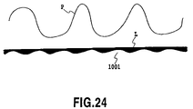
- FIGS. 24 , 25 , and 26 are diagrams illustrating the process of applying between a surface of the medium P and an applying surface in the case where the medium is ordinary paper. In these figures, the liquid is painted over with black.
- FIG. 24 shows the state of the upstream side of the nip portion between the applying roller 1001 and the counter roller 1002 .
- the liquid adheres to the applying surface of the applying roller 1001 so as to slightly cover the fine concaves and convexes on the applying surface.
- FIG. 25 shows the state of the surface of ordinary paper, the medium P, and the applying surface of the applying roller 1001 , at the nip portion between the applying roller 1001 and the counter roller 1002 .
- the convexes on the surface of the ordinary paper, the medium P contact the applying surface of the applying roller 1001 .
- the liquid instantaneously permeates through or sticks to fibers in the surface of the ordinary paper, the medium P, through the contacting parts.
- the liquid adhering to those parts of the applying surface of the applying roller which do not contact the convex portions on the surface of the ordinary paper remains on the applying surface.
- FIG. 26 shows the state of the downstream side of the nip portion between the applying roller 1001 and the counter roller 1002 .
- the medium has completely left the applying surface of the applying roller 1001 .
- the liquid adhering to those parts of the applying surface of the applying roller 1001 which do not contact with the convex portions on the surface of the ordinary paper remains on the applying surface.
- the liquid on the contacting parts also remains with very small amount on the coating surface.
- the application liquid is then mixed with the application liquid filled into the space S.
- the operation of returning the application liquid is similarly performed if the applying roller 1001 is rotated while no applying medium is present as shown in FIG. 10 . That is, the application liquid adhering to the outer periphery of the applying roller 1001 as a result of the rotation of the applying roller 1001 slipperily flows through the abutting portion between the applying roller 1001 and the counter roller 1002 . After flowing through the abutting portion, the application liquid is separated into two parts directed to the applying roller 1001 and the counter roller 1002 , respectively. The application liquid remains on the applying roller 1001 . Then, the application liquid adhering to the applying roller 1001 slipperily flows between the upper edge 2010 of the abutting member 2009 and the applying roller 1001 to enter the liquid holding space S. The application liquid is then mixed with the application liquid filled into the space S.
- circulation of the application liquid solves the following problem: when an area of the applying roller 1001 which has finished applying the liquid to the applying medium returns to the liquid holding space S, the application liquid remaining on the applying roller 1001 without being applied is disadvantageously mixed into the application liquid in the liquid holding space S, together with bubbles. This also solves the following problem: evaporation that may occur even in the liquid-tight liquid holding space S disadvantageously increases the concentration of the application liquid.
- the apparatus determines whether or not to finish the applying step. If the applying step is not to be finished, the process returns to step S 5 to repeat the applying operation until the applying step is executed on the all the parts of the applying medium to which the liquid needs to be applied.
- the applying roller 1001 is stopped (step S 7 ).
- the driving of the pump 3007 is stopped (step S 8 ).
- the process shifts to step S 2 to repeat the operations from step S 2 to step S 8 unless an applying start instruction is input before a predetermined period elapses. Even after the predetermined period has elapsed, if the applying start instruction is not input, a post process is executed such as a collecting operation of collecting the application liquid from the liquid holding space S and liquid channels (step S 9 ). Then, the coating process is finished.
- step S 8 the pump 3007 may not be stopped. In this case, after stopping the applying roller 1001 in step S 7 , the process proceeds to step S 2 .
- step S 9 the process of collecting the application liquid held by the liquid holding member 2001 is executed in step S 9 .
- the collecting process executed in step S 9 will be described below in detail with reference to FIG. 21 .
- FIG. 21 is a flowchart showing a process procedure for collecting a liquid in the liquid applying apparatus according to the present embodiment.
- step S 2 in FIG. 13 when the apparatus determines that the applying start instruction has not been input, the apparatus starts an operation of collecting the application liquid held in the liquid holding member 2001 .
- step S 21 the pump 3007 is driven in step S 21 in FIG. 21 to generate a flow from the pump 3007 to the storage tank 3003 .
- the pump 3007 is not stopped in step S 8 , the present step is not executed. Instead, when the application liquid collecting operation is started, the process proceeds to step S 22 .
- step S 22 the selector valve (three-way valve) 3006 is switched as shown in FIG. 20 .
- the air communicating port 3013 is thus allowed to communicate with the tube 3012 . That is, the supply path from the storage tank 3003 to the liquid holding member 2001 is shut off to inhibit the supply of the application liquid to the liquid holding member 2001 .
- the pump 3007 is creating a flow in the direction of an arrow in FIG. 11 , so that the application liquid present in the channel from the liquid holding tube 3012 to the second channel 3002 , including the liquid holding member 2001 , is collected in the storage tank 3003 . Further, they are filled with air from the air communicating port 3013 .
- step S 23 the driving of the pump 3003 is stopped. Then, the storage tank tube 30022 is shut off from the liquid holding member tube 30021 . Further, the tube 3011 is shut off from the tube 3012 by the selector valve 3006 .
- the pump 3007 may be stopped after a predetermined time elapses after the switching of the selector valve 3006 in step S 22 .
- the liquid holding member 2001 may contain means for sensing a timing for stopping the pump 3007 , for example, a sensor serving as means for sensing whether or not any application liquid remains in the liquid holding member 2001 . Then, the pump 3003 may be stopped on the basis of sensed information.
- step S 24 the air communicating port 3004 is closed. In this state, the storage tank 3003 is shut off from the air.
- the application liquid is collected from the liquid holding member 2001 to prevent the application liquid from being left in the liquid holding member 2001 for a long time. It is thus possible to reduce evaporation that may occur when the application liquid is left for a long time. Further, when the collecting operation is finished, the storage tank 3003 and thus the channels are shut off from the air. This makes it possible to prevent the application liquid from flowing out of the storage tank 3003 to the liquid holding member 2001 . Accordingly, even if the apparatus is, for example, tilted to change its posture during transportation or storage, the leakage of the liquid from the liquid holding member 2001 can be reduced.
- the selector valve 3006 is placed upstream of the pump 3007 .
- the pump 3007 may be placed on a supply path (in this case, the first channel 3001 ), whereas the selector valve 3006 may be placed on a collecting path (in this case, the second channel 3002 ).
- the selector valve 3006 is switched to allow the air communicating port 3013 to communicate with the liquid holding member side of the second channel 3002 .
- the storage tank side of the second channel 3002 is shut off from its liquid holding member side.
- the pump 3007 is reversely driven, that is, the rotation of the rotor 30071 of the pump 3007 is reversed to create a flow in the direction opposite to that of an arrow in FIG. 11 .
- This allows the application liquid in the liquid holding member 2001 and channels to be collected and collected in the storage tank 3003 .
- the pump is stopped (step S 23 ).
- the air communicating port 3004 in the storage tank is closed (step S 24 ).
- the reverse driving of the pump 3007 may be started before, after, or simultaneously with the switching of the selector valve 3006 .
- the pump 3007 may be placed on the first channel 3001 between the selector valve 3006 and the liquid holding member 2001 .
- means for preventing the countercurrent of the application liquid for example, a check valve (not shown), must be placed on the second channel.
- the check valve can prevent the application liquid collected in the storage tank 3003 from flowing to the liquid holding member 2001 .
- the pump 3007 used in the present embodiment has a function for shutting off the channels while not being driven.
- the check valve may be placed on the channel on which the pump 3007 is placed.
- the check valve may be placed on the storage tank 3003 side or the liquid holding member 2001 side with respect to the pump. Preferably, the check valve is placed on the storage tank 3003 side.
- the application liquid can be collected from the channels containing the liquid holding member to the storage tank by switching the selector valve having the air communicating port and driving the pump.
- the collecting makes it possible to reduce evaporation that may occur when the application liquid is left in the liquid holding member for a long time.
- the selector valve and the pump or on-off valve placed in the channel are used to shut off the application liquid channels.
- the air communicating port formed in the storage tank is also shut off from the air. Consequently, even if the application liquid flows out of the storage tank, it can be prevented from reaching the liquid holding member. Therefore, even if the apparatus is tilted during transportation or storage, no application liquid is present in the liquid holding member at that time. Naturally enough, no water head occurs, thus inhibiting the leakage of the liquid from the liquid holding member.
- the present embodiment is the applying apparatus described in the first embodiment wherein an on-off valve is used in place of the selector valve (three-way valve) 3006 to collect the liquid from the liquid holding space if the applying operation is not performed, the liquid holding space being formed between the applying roller and the liquid holding member to hold the liquid.
- an on-off valve is used in place of the selector valve (three-way valve) 3006 to collect the liquid from the liquid holding space if the applying operation is not performed, the liquid holding space being formed between the applying roller and the liquid holding member to hold the liquid.
- FIG. 22 is a diagram generally illustrating the configuration of the liquid channel connected to the liquid holding member according to the present invention.
- a first on-off valve 6001 and a second on-off valve 6002 are located in place of the selector valve (three-way valve) 3006 shown in FIG. 11 .
- the first channel 3001 has an air communicating port 6003 .
- the second on-off valve 6002 is provided on the air communication port 6003 .
- the first on-off valve 6001 is provided between the air communicating port 6003 and the storage tank 3003 .
- the combination of open and closed states of the first and second on-off valves enables the selective switching between a connected state in which the tubes 3011 and 3012 are in communication and a connected state in which the air communicating port 6003 and the tube 3012 are in communication.
- This switching makes it possible to selectively supply the application liquid or air in the storage tank 3003 to the liquid holding space S formed by the liquid holding member 2001 and the applying roller 1001 .
- Each of the first and second on-off valves 6001 and 6002 is opened and closed in accordance with a control signal from the control section 4000 , shown in FIG. 12 . The application liquid is thus filled or supplied.
- a process procedure for applying a liquid in the liquid applying apparatus is the same as that shown in FIG. 13 except for steps S 1 and S 9 . Accordingly, the description of the other steps is omitted. A detailed description will be given of steps S 1 and S 9 according to the present embodiment.
- step S 1 a step of filling the application liquid into the liquid holding space S is executed.
- the air communicating valve 3005 in the storage tank 3003 is opened to the air.
- the second on-off valve 6002 is closed, while the first on-off valve 6001 is opened, thus allowing the tubes 3011 and 3012 to communicate with each other.
- the pump 3007 is then driven for a specified time. This produces the same effect as that produced by the switching operation of the selector valve (three-way valve) 3006 .
- the application liquid is thus filled into the liquid holding member 2001 and channels as descried in step S 1 in FIG. 13 .
- step S 9 a process for collecting the application liquid held in the liquid holding member 2001 is executed in accordance with the process procedure shown in FIG. 21 .
- a process procedure for collecting a liquid is the same as that shown in FIG. 21 except for step S 22 . Accordingly, the description of the other steps is omitted. A detailed description will be given of step S 22 according to the present embodiment.
- step S 22 the second on-off valve 6002 is opened at the same time when the first on-off valve 6001 is closed.
- This allows the air communicating port 6003 to communicate with the tube 3012 . That is, the supply path from the storage tank 3003 to the liquid holding member 2001 is shut off by closing the first on-off valve 6001 .
- the pump 3007 is creating a flow in the direction of an arrow shown in FIG. 22 . Consequently, the application liquid in the channels containing the liquid holding member 2001 is collected in the storage tank 3003 .
- air from the air communicating port 6003 enters and fills the liquid holding member 2001 and the channels.
- the first on-off valve 6001 may be closed before the second on-off valve 6002 is opened.
- steps S 23 and S 24 are executed to finish the operation of collecting the application liquid. Then, the storage tank 3003 is shut off from the air.
- the application liquid can be collected from the channels including the liquid holding member to the storage tank, as in the first embodiment.
- the collecting makes it possible to reduce evaporation that may occur when the application liquid is left in the liquid holding member for a long time.
- the application liquid when the collecting of the application liquid is finished, the application liquid can be prevented from flowing out of the storage tank and reaching the liquid holding member. Therefore, even if the apparatus is tilted during transportation or storage, or the liquid holding member is separated from the applying roller or the pressure under which the liquid holding member is abutted against the applying roller is reduced when the collecting is finished, the liquid is prevented from leaking from the liquid holding member.
- the water head in a part of the channel connecting the storage tank and the liquid holding member together is set higher than the highest level in the storage tank.
- the liquid is selectively supplied to and collected from the liquid holding member by selectively enabling and disabling the communication between the high water head and the air.
- FIG. 23 is a diagram generally showing the configuration of an application liquid channel according to the present embodiment.
- the present embodiment for the configurations of the coating apparatus, liquid holding member, and liquid channel, parts similar to those in the second embodiment are denoted by the same reference numerals.
- the liquid holding member (liquid holding means) 2001 and the storage tank (storage means) 3003 are also connected together via the first channel 3001 and second channel 3002 .
- the pump 3007 is connected to the second channel 2002 .
- the first channel 3001 connects to an air introducing path 6005 at a connecting portion 6008 , the path 6005 having an air communicating port 6006 at its upper end.
- the air introducing path 6005 is provided with an on-off valve 6007 that selectively enables and disables the communication between the air communicating port 6006 and the connecting portion 6008 .
- the water head in the connecting portion 6008 is set higher (above in a gravitational direction) than the (highest) level (for example, f in the figure) in the storage tank 3003 .
- h 1 denotes a difference in water head between the level f and the connecting portion. Therefore, in this present embodiment, the air communicating valve 3005 in the storage tank 3003 is opened, while the on-off valve 6007 in the air introducing path 6005 is closed. The pump 3007 is then driven. This operation enables the application liquid in the storage tank 3003 to flow in the direction of an arrow in the figure. The liquid can thus be supplied to the interior of the liquid holding member 2001 .
- the pump 3007 is driven, while the on-off valve 6007 is opened.
- This allows the following application liquid to be collected in the storage tank 3003 under the driving force of the pump 3007 , the application liquid being present downstream of the connecting portion 6008 , that is, the application liquid being present in the area extending from the connecting portion 6008 of the first channel 3001 to the liquid holding member 2001 and in the liquid holding member 2001 and second channel 3002 .
- these portions are filled with air flowing in through the air communicating port 3004 .
- the following application liquid is collected owing to gravity until the level of the liquid becomes the same as that in the storage tank 3003 , the application liquid being present upstream of the connecting portion, that is, the application liquid being present in the area extending from the connecting portion 6008 of the first channel 3001 to the storage tank 3003 .
- the on-off valve 6007 is closed, while the air communicating valve 3005 is closed. This causes the storage tank 3003 , the first channel 3001 , the second channel 3002 , and the liquid holding member 2001 to be shut off from the air.
- the water head in the connecting portion 6008 is higher than the (highest) level in the storage tank 3003 . Accordingly, while the connecting portion 6008 is in communication with the air communicating port 6006 , the application liquid present upstream of the connecting portion 6008 does not flow downstream beyond the connecting portion 6008 .
- the connecting portion 6008 is placed so that its water head is higher than that of the liquid holding member 2001 as shown by h 2 in the figure. This is because when the connecting portion 6008 communicates with the air, the application liquid present downstream of the connecting portion 608 can be prevented from flowing backward toward the connecting portion 6008 and the air communicating port 6006 .
- the application liquid can also be collected from the channels including the liquid holding member to the storage tank as in the case of the first and second embodiments. This makes it possible to reduce evaporation that may occur when the application liquid is left in the liquid holding member for a long time.
- FIG. 14 is a diagram generally showing the configuration of an ink jet printing apparatus 1 comprising an applying mechanism having almost the same configuration as that of the above liquid applying apparatus.
- the ink jet printing apparatus 1 is provided with a feeding tray 2 on which a plurality of print media P are stacked.
- a semicircular separating roller 3 separates each print medium P from the others stacked on the feeding tray and then feeds it to a conveying path.
- the applying roller 1001 and the counter roller 1002 are arranged in the conveying path; the applying roller 1001 and the counter roller 1002 constitute liquid applying means of the liquid applying mechanism.
- the print medium P fed by the feeding tray 2 is then fed to between the rollers 1001 and 1002 .
- the applying roller 1001 is rotated clockwise in FIG. 14 by the rotation of a roller driving motor.
- the applying roller 1001 applies the application liquid to a print surface of the print medium P while conveying the print medium P.
- the print medium P to which the application liquid has been applied is fed to between a conveying roller 4 and a pinch roller 5 . Then, the conveying roller 4 is rotated counterclockwise in the figure to convey the print medium P on a platen 6 .
- the print medium P then moves to a position opposite to a print head 7 constituting printing means.
- the print head 7 is of an ink jet type in which a predetermined number of nozzles for ink ejection are disposed. While the print head 7 is being scanned in a direction perpendicular to the sheet of the drawing, printing is carried out by ejecting ink droplets from the nozzles to the print surface of the print medium P in accordance with print data.
- An image is formed on the print medium by alternately repeating a printing operation and a conveying operation performed by the conveying roller 4 to convey the print medium by a predetermined amount. Simultaneously with this image forming operation, the print medium P is sandwiched between a sheet discharging roller 8 and a sheet discharging spur 9 both provided downstream of the scan area of the print head in the conveying path for the print medium. The print medium P is then discharged onto a sheet discharging tray 10 by the rotation of the sheet discharging roller 8 .
- a full line type can be constructed in which an elongate print head having nozzles from which inks are ejected and which are disposed over the maximum width of the print medium is used to perform a printing operation.
- the application liquid used in the present embodiment is a treatment liquid that facilitates the coagulation of pigments when inks composed of the pigments as color materials are used for printing.
- the treatment liquid is used as an application liquid to react with the pigments, which are the color materials of the inks ejected to the print medium to which the treatment liquid has been applied.
- This facilitates the coagulation of the pigments.
- the facilitation of the coagulation of the pigments improves the printing density. Moreover, it is possible to suppress or prevent bleeding.
- the application liquid used in the ink jet printing apparatus is not limited to the above example.
- FIG. 15 is a perspective view showing an essential part of the above ink jet printing apparatus. As shown in the figure, an applying mechanism 100 is provided above one end of the feeding tray 2 . A printing mechanism comprising the print head 7 and the like is provided above the applying mechanism 100 and above a central portion of the feeding tray 2 .
- FIG. 16 is a block diagram showing a control arrangement for the above ink jet printing apparatus.
- the roller driving motor 1004 , the pump driving motor 4009 , and the actuator 3005 for the air communicating valve, all of which are elements of the liquid applying mechanism, are similar to those descried for the liquid applying apparatus.
- a CPU 5001 controls the driving of the elements of the applying mechanism.
- the CPU 5001 also controls the driving of an LF motor 5013 , a CR motor 5015 , and the print head 7 which relate to the printing mechanism, via driving circuits 5012 and 5014 and a head driver 5016 . That is, driving by the LF motor 5013 rotates the conveying roller 4 . Driving by the CR motor moves a carriage on which the print head 7 is mounted.
- the CPU 5001 performs control such that inks are ejected through the nozzles in the print head.
- FIG. 17 is a flowchart showing the procedure of liquid application and an accompanying printing operation in the ink jet printing apparatus according to the present embodiment.
- the processing during steps S 101 , during S 103 to S 105 , and during S 108 to S 110 is similar to that during step S 1 , during steps S 3 to S 5 , and during steps S 7 to S 9 , all the steps being shown in FIG. 13 .
- a print start instruction is given (step S 102 ).
- a series of liquid applying operations such as pump activation are performed (steps S 103 to S 105 ).
- a printing operation is performed on a print medium having the application liquid applied to desired parts of the medium (step S 106 ). That is, the print head 7 is scanned over the print medium P conveyed by the conveying roller 4 by a predetermined amount at a time. During the scan, inks are ejected from the nozzles in accordance with print data so as to adhere to the print medium to form dots. The adhering inks react with the application liquid, thus improving the concentration and preventing bleeding. The conveyance of the print medium and the scanning of the print head are repeated to print the print medium P. The finished print medium is discharged onto the sheet discharging tray 10 .
- the applying mechanism applies the liquid to another part of the print medium. Every time the print medium is conveyed by a predetermined amount, liquid application and printing are sequentially executed on different parts of the print medium.
- printing may be carried out after one print medium has been completely applied the application liquid to as described in Japanese Patent Application Laid-open No. 2002-096452.
- step S 107 When the apparatus determines in step S 107 that the printing has been finished, the processing in step S 108 and the subsequent steps is executed to finish the present process.
- the liquid is applied in the ink jet printing-based printing apparatus.
- the present invention is applicable to printing apparatuses based on other systems.
- the degree of whiteness of the medium can be improved by using a liquid containing a fluorescent whitening agent as a application liquid.
- a liquid containing components to restrain a curl (phenomenon in which a medium becomes curve shape) of the application medium may be used.
- the printing means after the liquid application is not limited to the ink jet printing system. Effects can be produced using a printing system such as a thermal transfer system or an electrophotographic system.
- a photosensitive agent as the application liquid may be applied before printing.
- the apparatus may determine in step S 2 in FIG. 13 or in step S 102 in FIG. 17 that the applying start instruction has not been input. Then, before the process proceeds to step S 9 in FIG. 13 or step S 110 in FIG. 17 , the apparatus may determine whether or not a predetermined time has elapsed since the start of a standby mode of the liquid applying apparatus or ink jet printing apparatus.
- step S 9 in FIG. 13 or step S 110 in FIG. 117 determines that the predetermined time has elapsed since the start of the standby mode. If the apparatus determines that the predetermined time has not elapsed since the start of the standby mode, it proceeds to step S 2 in FIG. 13 or step S 102 in FIG. 117 to determine whether or not the applying start instruction has been input.
- step S 9 or S 100 a process procedure concerning the collecting of the application liquid shown in FIG. 21 is executed to collect the application liquid in the storage tank 3003 .
Landscapes
- Coating Apparatus (AREA)
- Ink Jet (AREA)
- Application Of Or Painting With Fluid Materials (AREA)
Applications Claiming Priority (2)
| Application Number | Priority Date | Filing Date | Title |
|---|---|---|---|
| JP2004-035805 | 2004-02-12 | ||
| JP2004035805 | 2004-02-12 |
Publications (2)
| Publication Number | Publication Date |
|---|---|
| US20050200666A1 US20050200666A1 (en) | 2005-09-15 |
| US7270409B2 true US7270409B2 (en) | 2007-09-18 |
Family
ID=34697912
Family Applications (1)
| Application Number | Title | Priority Date | Filing Date |
|---|---|---|---|
| US11/052,023 Expired - Fee Related US7270409B2 (en) | 2004-02-12 | 2005-02-08 | Liquid applying apparatus and ink jet printing apparatus |
Country Status (3)
| Country | Link |
|---|---|
| US (1) | US7270409B2 (de) |
| EP (1) | EP1564010B1 (de) |
| CN (1) | CN100368199C (de) |
Cited By (10)
| Publication number | Priority date | Publication date | Assignee | Title |
|---|---|---|---|---|
| US20050179720A1 (en) * | 2004-02-12 | 2005-08-18 | Canon Kabushiki Kaisha | Liquid applying apparatus and ink jet printing apparatus |
| US20080223290A1 (en) * | 2004-02-12 | 2008-09-18 | Canon Kabushiki Kaisha | Liquid applying apparatus and ink jet printing apparatus |
| US20080278555A1 (en) * | 2004-02-12 | 2008-11-13 | C/O Canon Kabushiki Kaisha | Ink jet printing apparatus |
| US20100060688A1 (en) * | 2008-09-05 | 2010-03-11 | Katsuyuki Hirato | Liquid application apparatus, liquid application method and image forming apparatus |
| US20100154706A1 (en) * | 2008-12-19 | 2010-06-24 | Canon Kabushiki Kaisha | Liquid applying apparatus |
| US20110011337A1 (en) * | 2009-07-14 | 2011-01-20 | Samsung Electronics Co., Ltd | Image forming apparatus |
| US8726834B2 (en) | 2006-12-11 | 2014-05-20 | Canon Kabushiki Kaisha | Liquid applying apparatus and ink jet printing apparatus |
| US8827419B2 (en) | 2012-05-08 | 2014-09-09 | Canon Kabushiki Kaisha | Printing apparatus and control method therefor |
| US8944562B2 (en) | 2012-05-07 | 2015-02-03 | Canon Kabushiki Kaisha | Printing apparatus and control method therefor |
| US11511549B2 (en) | 2017-09-29 | 2022-11-29 | Canon Kabushiki Kaisha | Liquid ejection apparatus, liquid ejection head, and recovery method |
Families Citing this family (13)
| Publication number | Priority date | Publication date | Assignee | Title |
|---|---|---|---|---|
| DE602006012896D1 (de) * | 2005-04-28 | 2010-04-29 | Brother Ind Ltd | Tintenstrahlaufzeichnungsapparat und Steuerung desselben |
| JP4480166B2 (ja) * | 2005-08-11 | 2010-06-16 | キヤノン株式会社 | 液体塗布装置およびインクジェット記録装置 |
| JP5116471B2 (ja) | 2005-08-15 | 2013-01-09 | キヤノン株式会社 | 液体塗布装置およびインクジェット記録装置 |
| JP2007099834A (ja) * | 2005-09-30 | 2007-04-19 | Fujifilm Corp | インク組成物、インクセット及びインクジェット画像記録方法 |
| CN101121323B (zh) * | 2006-08-09 | 2012-06-20 | 鸿富锦精密工业(深圳)有限公司 | 喷墨系统及维持喷墨头与墨池之间压力差恒定的方法 |
| JP5148440B2 (ja) * | 2008-09-29 | 2013-02-20 | 富士フイルム株式会社 | 液体塗布装置、液体貯蔵方法及びインクジェット記録装置 |
| DE102009007590A1 (de) * | 2009-02-05 | 2010-09-09 | Hauni Maschinenbau Ag | Beleimung von Materialstreifen der Tabak verarbeitenden Industrie |
| KR101695333B1 (ko) * | 2009-11-13 | 2017-01-12 | 주식회사 탑 엔지니어링 | 액정 공급장치 및 액정 공급 및 회수방법 |
| JP5464492B2 (ja) * | 2010-06-16 | 2014-04-09 | 株式会社リコー | 画像形成装置及び処理液付与装置 |
| US8840230B2 (en) * | 2012-06-04 | 2014-09-23 | Xerox Corporation | Ink waste tray configured with one way filter |
| JP6068271B2 (ja) * | 2013-06-10 | 2017-01-25 | 東レ株式会社 | 塗布器、及び塗布装置 |
| JP6884991B2 (ja) * | 2016-05-26 | 2021-06-09 | セイコーエプソン株式会社 | 液体供給弁および流路システム並びに液体供給弁の使用方法 |
| CN115415103B (zh) * | 2022-09-14 | 2024-05-24 | 汕头市鼎泰丰实业有限公司 | 一种纺织面料表面处理用智能化涂布设备及涂布工艺 |
Citations (18)
| Publication number | Priority date | Publication date | Assignee | Title |
|---|---|---|---|---|
| US3905785A (en) | 1972-04-27 | 1975-09-16 | Air Ind | Spray booth bottom collector |
| US4284343A (en) * | 1978-08-12 | 1981-08-18 | Hoechst Aktiengesellschaft | Apparatus for the electric level control of a developing solution in a storage tank |
| US4449476A (en) * | 1982-01-30 | 1984-05-22 | Gebrueder Sucker | Apparatus for coating or impregnating a guided substrate in the form of a web |
| US4949667A (en) * | 1988-04-20 | 1990-08-21 | Dainippon Screen Mfg. Co., Ltd. | Roll coating apparatus for forming a film of a high viscosity coating liquid on a surface |
| US5045888A (en) * | 1989-05-30 | 1991-09-03 | Brother Kogyo Kabushiki Kaisha | Image fixing device and method for fixing image |
| US5056036A (en) * | 1989-10-20 | 1991-10-08 | Pulsafeeder, Inc. | Computer controlled metering pump |
| US5132706A (en) * | 1989-04-12 | 1992-07-21 | Canon Kabushiki Kaisha | Transferring ink with an adhesive characteristic changed by applied voltage and replacing component loss of ink in response to determined changes of ink |
| US5207159A (en) | 1991-08-30 | 1993-05-04 | Howard W. DeMoore | Coating apparatus for sheet-fed, offset rotary printing presses |
| US5367982A (en) | 1993-02-25 | 1994-11-29 | Howard W. DeMoore | Automatic coating circulation and wash-up system for printing presses |
| JPH0858069A (ja) | 1994-08-24 | 1996-03-05 | Fuji Kikai Kogyo Kk | グラビア印刷機のインク供給装置 |
| JPH0872227A (ja) | 1994-09-02 | 1996-03-19 | Canon Inc | 画像形成装置 |
| US5960713A (en) | 1995-05-04 | 1999-10-05 | Howard W. DeMoore | Retractable printing-coating unit operable on the plate and blanket cylinders simultaneously from the dampener side of the first printing unit or any consecutive printing unit or any rotary offset printing press |
| US5993524A (en) * | 1997-09-04 | 1999-11-30 | Ricoh Company, Ltd. | Image recording method, image recording apparatus and image recording acceleration liquid |
| CN1263798A (zh) | 1999-02-10 | 2000-08-23 | 松下电器产业株式会社 | 断续涂敷设备和断续涂敷方法 |
| US6183079B1 (en) | 1998-06-11 | 2001-02-06 | Lexmark International, Inc. | Coating apparatus for use in an ink jet printer |
| JP2001070858A (ja) | 1999-07-07 | 2001-03-21 | Canon Inc | 塗料の塗工装置および塗工方法 |
| JP2002096452A (ja) | 2000-09-22 | 2002-04-02 | Ricoh Co Ltd | 画像記録装置 |
| US6706118B2 (en) * | 2002-02-26 | 2004-03-16 | Lexmark International, Inc. | Apparatus and method of using motion control to improve coatweight uniformity in intermittent coaters in an inkjet printer |
Family Cites Families (3)
| Publication number | Priority date | Publication date | Assignee | Title |
|---|---|---|---|---|
| DE3909879C1 (de) * | 1989-03-25 | 1990-08-09 | Man Roland Druckmaschinen Ag, 6050 Offenbach, De | |
| US6383296B1 (en) * | 1999-11-22 | 2002-05-07 | Harris & Bruno Machine Co. | Chambered doctor blade with automatic cleanup and ink replacement |
| US6585364B2 (en) * | 2001-05-29 | 2003-07-01 | Hewlett-Packard Development Company, L.P. | Methods and apparatus for improving inkjet print quality |
-
2005
- 2005-02-07 CN CNB200510008252XA patent/CN100368199C/zh not_active Expired - Fee Related
- 2005-02-08 US US11/052,023 patent/US7270409B2/en not_active Expired - Fee Related
- 2005-02-10 EP EP05002780.4A patent/EP1564010B1/de not_active Expired - Lifetime
Patent Citations (21)
| Publication number | Priority date | Publication date | Assignee | Title |
|---|---|---|---|---|
| US3905785A (en) | 1972-04-27 | 1975-09-16 | Air Ind | Spray booth bottom collector |
| US4284343A (en) * | 1978-08-12 | 1981-08-18 | Hoechst Aktiengesellschaft | Apparatus for the electric level control of a developing solution in a storage tank |
| US4449476A (en) * | 1982-01-30 | 1984-05-22 | Gebrueder Sucker | Apparatus for coating or impregnating a guided substrate in the form of a web |
| US4949667A (en) * | 1988-04-20 | 1990-08-21 | Dainippon Screen Mfg. Co., Ltd. | Roll coating apparatus for forming a film of a high viscosity coating liquid on a surface |
| US5132706A (en) * | 1989-04-12 | 1992-07-21 | Canon Kabushiki Kaisha | Transferring ink with an adhesive characteristic changed by applied voltage and replacing component loss of ink in response to determined changes of ink |
| US5045888A (en) * | 1989-05-30 | 1991-09-03 | Brother Kogyo Kabushiki Kaisha | Image fixing device and method for fixing image |
| US5056036A (en) * | 1989-10-20 | 1991-10-08 | Pulsafeeder, Inc. | Computer controlled metering pump |
| US5207159A (en) | 1991-08-30 | 1993-05-04 | Howard W. DeMoore | Coating apparatus for sheet-fed, offset rotary printing presses |
| CN1079689A (zh) | 1992-05-06 | 1993-12-22 | 霍华德·沃伦·德穆尔 | 用于单张纸轮转胶印机的涂敷装置 |
| US5367982A (en) | 1993-02-25 | 1994-11-29 | Howard W. DeMoore | Automatic coating circulation and wash-up system for printing presses |
| JPH0858069A (ja) | 1994-08-24 | 1996-03-05 | Fuji Kikai Kogyo Kk | グラビア印刷機のインク供給装置 |
| JPH0872227A (ja) | 1994-09-02 | 1996-03-19 | Canon Inc | 画像形成装置 |
| US5960713A (en) | 1995-05-04 | 1999-10-05 | Howard W. DeMoore | Retractable printing-coating unit operable on the plate and blanket cylinders simultaneously from the dampener side of the first printing unit or any consecutive printing unit or any rotary offset printing press |
| US5993524A (en) * | 1997-09-04 | 1999-11-30 | Ricoh Company, Ltd. | Image recording method, image recording apparatus and image recording acceleration liquid |
| US6183079B1 (en) | 1998-06-11 | 2001-02-06 | Lexmark International, Inc. | Coating apparatus for use in an ink jet printer |
| JP2002517341A (ja) | 1998-06-11 | 2002-06-18 | レックスマーク・インターナショナル・インコーポレーテツド | インクジェットプリンタ用のコーティング機構 |
| CN1263798A (zh) | 1999-02-10 | 2000-08-23 | 松下电器产业株式会社 | 断续涂敷设备和断续涂敷方法 |
| US7105203B1 (en) | 1999-02-10 | 2006-09-12 | Mastsushita Electric Industrial Co., Ltd. | Intermittent coating apparatus and intermittent coating method |
| JP2001070858A (ja) | 1999-07-07 | 2001-03-21 | Canon Inc | 塗料の塗工装置および塗工方法 |
| JP2002096452A (ja) | 2000-09-22 | 2002-04-02 | Ricoh Co Ltd | 画像記録装置 |
| US6706118B2 (en) * | 2002-02-26 | 2004-03-16 | Lexmark International, Inc. | Apparatus and method of using motion control to improve coatweight uniformity in intermittent coaters in an inkjet printer |
Non-Patent Citations (1)
| Title |
|---|
| Chinese Office Action, issued on Dec. 22, 2006, in Chinese Application No. 200510008252.X and its English translation. |
Cited By (16)
| Publication number | Priority date | Publication date | Assignee | Title |
|---|---|---|---|---|
| US8038268B2 (en) | 2004-02-12 | 2011-10-18 | Canon Kabushiki Kaisha | Liquid applying apparatus and ink jet printing apparatus |
| US20080223290A1 (en) * | 2004-02-12 | 2008-09-18 | Canon Kabushiki Kaisha | Liquid applying apparatus and ink jet printing apparatus |
| US20080278555A1 (en) * | 2004-02-12 | 2008-11-13 | C/O Canon Kabushiki Kaisha | Ink jet printing apparatus |
| US20080297573A1 (en) * | 2004-02-12 | 2008-12-04 | Canon Kabushiki Kaisha | Liquid applying apparatus and ink jet printing apparatus |
| US7461932B2 (en) * | 2004-02-12 | 2008-12-09 | Canon Kabushiki Kaisha | Ink jet printing apparatus for preventing degradation of liquid application member |
| US7588639B2 (en) | 2004-02-12 | 2009-09-15 | Canon Kabushiki Kaisha | Liquid applying apparatus and ink jet printing apparatus |
| US20050179720A1 (en) * | 2004-02-12 | 2005-08-18 | Canon Kabushiki Kaisha | Liquid applying apparatus and ink jet printing apparatus |
| US8087744B2 (en) | 2004-02-12 | 2012-01-03 | Canon Kabushiki Kaisha | Ink jet printing apparatus |
| US8726834B2 (en) | 2006-12-11 | 2014-05-20 | Canon Kabushiki Kaisha | Liquid applying apparatus and ink jet printing apparatus |
| US8333464B2 (en) * | 2008-09-05 | 2012-12-18 | Fujifilm Corporation | Liquid application apparatus, liquid application method and image forming apparatus |
| US20100060688A1 (en) * | 2008-09-05 | 2010-03-11 | Katsuyuki Hirato | Liquid application apparatus, liquid application method and image forming apparatus |
| US20100154706A1 (en) * | 2008-12-19 | 2010-06-24 | Canon Kabushiki Kaisha | Liquid applying apparatus |
| US20110011337A1 (en) * | 2009-07-14 | 2011-01-20 | Samsung Electronics Co., Ltd | Image forming apparatus |
| US8944562B2 (en) | 2012-05-07 | 2015-02-03 | Canon Kabushiki Kaisha | Printing apparatus and control method therefor |
| US8827419B2 (en) | 2012-05-08 | 2014-09-09 | Canon Kabushiki Kaisha | Printing apparatus and control method therefor |
| US11511549B2 (en) | 2017-09-29 | 2022-11-29 | Canon Kabushiki Kaisha | Liquid ejection apparatus, liquid ejection head, and recovery method |
Also Published As
| Publication number | Publication date |
|---|---|
| CN1654207A (zh) | 2005-08-17 |
| EP1564010A2 (de) | 2005-08-17 |
| CN100368199C (zh) | 2008-02-13 |
| EP1564010A3 (de) | 2010-05-26 |
| US20050200666A1 (en) | 2005-09-15 |
| EP1564010B1 (de) | 2017-04-12 |
Similar Documents
| Publication | Publication Date | Title |
|---|---|---|
| US7270409B2 (en) | Liquid applying apparatus and ink jet printing apparatus | |
| US8038268B2 (en) | Liquid applying apparatus and ink jet printing apparatus | |
| US8087744B2 (en) | Ink jet printing apparatus | |
| US7588639B2 (en) | Liquid applying apparatus and ink jet printing apparatus | |
| US7650850B2 (en) | Liquid applying apparatus and ink jet printing apparatus | |
| US7537661B2 (en) | Liquid applying apparatus and ink-jet printing apparatus | |
| EP2082810B1 (de) | Flüssigkeitsauftragsvorrichtung und Druckvorrichtung | |
| JP4669347B2 (ja) | 液体塗布装置およびインクジェット記録装置 | |
| US7896966B2 (en) | Liquid applying apparatus and ink-jet printing apparatus | |
| JP5371226B2 (ja) | 液体塗布装置およびインクジェット記録装置 | |
| JP4677246B2 (ja) | インクジェット記録装置 | |
| US7536974B2 (en) | Liquid applying apparatus and printing apparatus | |
| JP4748768B2 (ja) | インクジェット記録装置 | |
| JP4355662B2 (ja) | インクジェット記録装置 | |
| JP4508978B2 (ja) | 液体塗布装置およびインクジェット記録装置 | |
| JP2008149231A (ja) | 液体塗布装置およびインクジェット記録装置 |
Legal Events
| Date | Code | Title | Description |
|---|---|---|---|
| AS | Assignment |
Owner name: CANON KABUSHIKI KAISHA, JAPAN Free format text: ASSIGNMENT OF ASSIGNORS INTEREST;ASSIGNORS:IWASAKI, OSAMU;OTSUKA, NAOJI;NAKAGAWA, YOSHINORI;REEL/FRAME:016252/0228;SIGNING DATES FROM 20050203 TO 20050204 |
|
| CC | Certificate of correction | ||
| FPAY | Fee payment |
Year of fee payment: 4 |
|
| REMI | Maintenance fee reminder mailed | ||
| LAPS | Lapse for failure to pay maintenance fees | ||
| STCH | Information on status: patent discontinuation |
Free format text: PATENT EXPIRED DUE TO NONPAYMENT OF MAINTENANCE FEES UNDER 37 CFR 1.362 |
|
| STCH | Information on status: patent discontinuation |
Free format text: PATENT EXPIRED DUE TO NONPAYMENT OF MAINTENANCE FEES UNDER 37 CFR 1.362 |
|
| FP | Lapsed due to failure to pay maintenance fee |
Effective date: 20150918 |