EP1563992B1 - Plaque d'impression avec plusieurs couches fonctionelles - Google Patents
Plaque d'impression avec plusieurs couches fonctionelles Download PDFInfo
- Publication number
- EP1563992B1 EP1563992B1 EP05100599.9A EP05100599A EP1563992B1 EP 1563992 B1 EP1563992 B1 EP 1563992B1 EP 05100599 A EP05100599 A EP 05100599A EP 1563992 B1 EP1563992 B1 EP 1563992B1
- Authority
- EP
- European Patent Office
- Prior art keywords
- zone
- layer
- absorption
- energy
- printing
- Prior art date
- Legal status (The legal status is an assumption and is not a legal conclusion. Google has not performed a legal analysis and makes no representation as to the accuracy of the status listed.)
- Expired - Lifetime
Links
- 238000007639 printing Methods 0.000 title claims description 91
- 239000002346 layers by function Substances 0.000 title 1
- 238000010521 absorption reaction Methods 0.000 claims description 79
- 230000005855 radiation Effects 0.000 claims description 47
- 229920000642 polymer Polymers 0.000 claims description 19
- 238000002955 isolation Methods 0.000 claims description 15
- 230000003139 buffering effect Effects 0.000 claims description 11
- 239000000872 buffer Substances 0.000 description 66
- 239000000463 material Substances 0.000 description 28
- 238000003384 imaging method Methods 0.000 description 24
- RTAQQCXQSZGOHL-UHFFFAOYSA-N Titanium Chemical compound [Ti] RTAQQCXQSZGOHL-UHFFFAOYSA-N 0.000 description 19
- 238000000034 method Methods 0.000 description 18
- 229910052799 carbon Inorganic materials 0.000 description 17
- 229910052757 nitrogen Inorganic materials 0.000 description 17
- 229920001721 polyimide Polymers 0.000 description 17
- 230000008569 process Effects 0.000 description 17
- IJGRMHOSHXDMSA-UHFFFAOYSA-N Atomic nitrogen Chemical compound N#N IJGRMHOSHXDMSA-UHFFFAOYSA-N 0.000 description 16
- ZOKXTWBITQBERF-UHFFFAOYSA-N Molybdenum Chemical compound [Mo] ZOKXTWBITQBERF-UHFFFAOYSA-N 0.000 description 14
- 239000010936 titanium Substances 0.000 description 13
- 229910052719 titanium Inorganic materials 0.000 description 12
- 238000009413 insulation Methods 0.000 description 11
- OKTJSMMVPCPJKN-UHFFFAOYSA-N Carbon Chemical compound [C] OKTJSMMVPCPJKN-UHFFFAOYSA-N 0.000 description 8
- 229910052751 metal Inorganic materials 0.000 description 8
- 239000002184 metal Substances 0.000 description 8
- 229910052760 oxygen Inorganic materials 0.000 description 8
- 239000001301 oxygen Substances 0.000 description 8
- 230000035515 penetration Effects 0.000 description 8
- 239000004642 Polyimide Substances 0.000 description 7
- 230000008901 benefit Effects 0.000 description 7
- 229910052750 molybdenum Inorganic materials 0.000 description 7
- 239000011733 molybdenum Substances 0.000 description 7
- 229910010413 TiO 2 Inorganic materials 0.000 description 6
- 229910052782 aluminium Inorganic materials 0.000 description 6
- XAGFODPZIPBFFR-UHFFFAOYSA-N aluminium Chemical compound [Al] XAGFODPZIPBFFR-UHFFFAOYSA-N 0.000 description 6
- 230000008878 coupling Effects 0.000 description 6
- 238000010168 coupling process Methods 0.000 description 6
- 238000005859 coupling reaction Methods 0.000 description 6
- 239000000126 substance Substances 0.000 description 6
- GWEVSGVZZGPLCZ-UHFFFAOYSA-N Titan oxide Chemical compound O=[Ti]=O GWEVSGVZZGPLCZ-UHFFFAOYSA-N 0.000 description 5
- 239000006117 anti-reflective coating Substances 0.000 description 5
- 230000005540 biological transmission Effects 0.000 description 5
- 230000002209 hydrophobic effect Effects 0.000 description 5
- 239000000203 mixture Substances 0.000 description 5
- MYMOFIZGZYHOMD-UHFFFAOYSA-N Dioxygen Chemical compound O=O MYMOFIZGZYHOMD-UHFFFAOYSA-N 0.000 description 4
- VYPSYNLAJGMNEJ-UHFFFAOYSA-N Silicium dioxide Chemical compound O=[Si]=O VYPSYNLAJGMNEJ-UHFFFAOYSA-N 0.000 description 4
- QVGXLLKOCUKJST-UHFFFAOYSA-N atomic oxygen Chemical compound [O] QVGXLLKOCUKJST-UHFFFAOYSA-N 0.000 description 4
- 238000007645 offset printing Methods 0.000 description 4
- 229920003223 poly(pyromellitimide-1,4-diphenyl ether) Polymers 0.000 description 4
- VYZAMTAEIAYCRO-UHFFFAOYSA-N Chromium Chemical compound [Cr] VYZAMTAEIAYCRO-UHFFFAOYSA-N 0.000 description 3
- 230000003667 anti-reflective effect Effects 0.000 description 3
- 239000000919 ceramic Substances 0.000 description 3
- 239000011651 chromium Substances 0.000 description 3
- 230000006378 damage Effects 0.000 description 3
- 239000012212 insulator Substances 0.000 description 3
- 230000003287 optical effect Effects 0.000 description 3
- 230000000737 periodic effect Effects 0.000 description 3
- 229910001220 stainless steel Inorganic materials 0.000 description 3
- 239000010935 stainless steel Substances 0.000 description 3
- 239000000758 substrate Substances 0.000 description 3
- ATJFFYVFTNAWJD-UHFFFAOYSA-N Tin Chemical compound [Sn] ATJFFYVFTNAWJD-UHFFFAOYSA-N 0.000 description 2
- 238000005299 abrasion Methods 0.000 description 2
- 230000015572 biosynthetic process Effects 0.000 description 2
- 238000006243 chemical reaction Methods 0.000 description 2
- 229910052804 chromium Inorganic materials 0.000 description 2
- 238000000576 coating method Methods 0.000 description 2
- 230000001066 destructive effect Effects 0.000 description 2
- 238000010438 heat treatment Methods 0.000 description 2
- 239000011572 manganese Substances 0.000 description 2
- 238000002844 melting Methods 0.000 description 2
- 230000008018 melting Effects 0.000 description 2
- 229910044991 metal oxide Inorganic materials 0.000 description 2
- 150000004706 metal oxides Chemical class 0.000 description 2
- 150000002739 metals Chemical class 0.000 description 2
- 238000002156 mixing Methods 0.000 description 2
- 150000004767 nitrides Chemical class 0.000 description 2
- 238000007711 solidification Methods 0.000 description 2
- 230000008023 solidification Effects 0.000 description 2
- 238000003860 storage Methods 0.000 description 2
- 238000009736 wetting Methods 0.000 description 2
- XEEYBQQBJWHFJM-UHFFFAOYSA-N Iron Chemical compound [Fe] XEEYBQQBJWHFJM-UHFFFAOYSA-N 0.000 description 1
- PWHULOQIROXLJO-UHFFFAOYSA-N Manganese Chemical compound [Mn] PWHULOQIROXLJO-UHFFFAOYSA-N 0.000 description 1
- ABLZXFCXXLZCGV-UHFFFAOYSA-N Phosphorous acid Chemical compound OP(O)=O ABLZXFCXXLZCGV-UHFFFAOYSA-N 0.000 description 1
- 229910004298 SiO 2 Inorganic materials 0.000 description 1
- 229910000831 Steel Inorganic materials 0.000 description 1
- 229910010421 TiNx Inorganic materials 0.000 description 1
- 230000002378 acidificating effect Effects 0.000 description 1
- 230000004913 activation Effects 0.000 description 1
- 238000004026 adhesive bonding Methods 0.000 description 1
- 239000004411 aluminium Substances 0.000 description 1
- 235000019577 caloric intake Nutrition 0.000 description 1
- 239000012876 carrier material Substances 0.000 description 1
- 230000008859 change Effects 0.000 description 1
- 238000001311 chemical methods and process Methods 0.000 description 1
- 239000011248 coating agent Substances 0.000 description 1
- 238000011161 development Methods 0.000 description 1
- 230000018109 developmental process Effects 0.000 description 1
- 238000001035 drying Methods 0.000 description 1
- 230000000694 effects Effects 0.000 description 1
- 230000005670 electromagnetic radiation Effects 0.000 description 1
- 238000005265 energy consumption Methods 0.000 description 1
- 238000004146 energy storage Methods 0.000 description 1
- 230000004927 fusion Effects 0.000 description 1
- 239000011521 glass Substances 0.000 description 1
- 230000017525 heat dissipation Effects 0.000 description 1
- 229910052748 manganese Inorganic materials 0.000 description 1
- 238000004519 manufacturing process Methods 0.000 description 1
- 239000002105 nanoparticle Substances 0.000 description 1
- 229910052755 nonmetal Inorganic materials 0.000 description 1
- 150000002894 organic compounds Chemical class 0.000 description 1
- 238000013021 overheating Methods 0.000 description 1
- 238000000059 patterning Methods 0.000 description 1
- 230000001699 photocatalysis Effects 0.000 description 1
- 239000000049 pigment Substances 0.000 description 1
- 229920006254 polymer film Polymers 0.000 description 1
- 239000012286 potassium permanganate Substances 0.000 description 1
- 238000004064 recycling Methods 0.000 description 1
- VSZWPYCFIRKVQL-UHFFFAOYSA-N selanylidenegallium;selenium Chemical compound [Se].[Se]=[Ga].[Se]=[Ga] VSZWPYCFIRKVQL-UHFFFAOYSA-N 0.000 description 1
- 239000004065 semiconductor Substances 0.000 description 1
- 235000012239 silicon dioxide Nutrition 0.000 description 1
- 239000000377 silicon dioxide Substances 0.000 description 1
- 239000002904 solvent Substances 0.000 description 1
- 239000010959 steel Substances 0.000 description 1
- 230000035882 stress Effects 0.000 description 1
- 229910052715 tantalum Inorganic materials 0.000 description 1
- GUVRBAGPIYLISA-UHFFFAOYSA-N tantalum atom Chemical compound [Ta] GUVRBAGPIYLISA-UHFFFAOYSA-N 0.000 description 1
- JBQYATWDVHIOAR-UHFFFAOYSA-N tellanylidenegermanium Chemical compound [Te]=[Ge] JBQYATWDVHIOAR-UHFFFAOYSA-N 0.000 description 1
- 230000008646 thermal stress Effects 0.000 description 1
- OGIDPMRJRNCKJF-UHFFFAOYSA-N titanium oxide Inorganic materials [Ti]=O OGIDPMRJRNCKJF-UHFFFAOYSA-N 0.000 description 1
- 230000007704 transition Effects 0.000 description 1
- 238000009827 uniform distribution Methods 0.000 description 1
- XLYOFNOQVPJJNP-UHFFFAOYSA-N water Substances O XLYOFNOQVPJJNP-UHFFFAOYSA-N 0.000 description 1
Images

Classifications
-
- B—PERFORMING OPERATIONS; TRANSPORTING
- B41—PRINTING; LINING MACHINES; TYPEWRITERS; STAMPS
- B41N—PRINTING PLATES OR FOILS; MATERIALS FOR SURFACES USED IN PRINTING MACHINES FOR PRINTING, INKING, DAMPING, OR THE LIKE; PREPARING SUCH SURFACES FOR USE AND CONSERVING THEM
- B41N1/00—Printing plates or foils; Materials therefor
- B41N1/04—Printing plates or foils; Materials therefor metallic
- B41N1/08—Printing plates or foils; Materials therefor metallic for lithographic printing
-
- B—PERFORMING OPERATIONS; TRANSPORTING
- B41—PRINTING; LINING MACHINES; TYPEWRITERS; STAMPS
- B41C—PROCESSES FOR THE MANUFACTURE OR REPRODUCTION OF PRINTING SURFACES
- B41C1/00—Forme preparation
- B41C1/10—Forme preparation for lithographic printing; Master sheets for transferring a lithographic image to the forme
-
- B—PERFORMING OPERATIONS; TRANSPORTING
- B41—PRINTING; LINING MACHINES; TYPEWRITERS; STAMPS
- B41N—PRINTING PLATES OR FOILS; MATERIALS FOR SURFACES USED IN PRINTING MACHINES FOR PRINTING, INKING, DAMPING, OR THE LIKE; PREPARING SUCH SURFACES FOR USE AND CONSERVING THEM
- B41N1/00—Printing plates or foils; Materials therefor
- B41N1/12—Printing plates or foils; Materials therefor non-metallic other than stone, e.g. printing plates or foils comprising inorganic materials in an organic matrix
- B41N1/14—Lithographic printing foils
-
- Y—GENERAL TAGGING OF NEW TECHNOLOGICAL DEVELOPMENTS; GENERAL TAGGING OF CROSS-SECTIONAL TECHNOLOGIES SPANNING OVER SEVERAL SECTIONS OF THE IPC; TECHNICAL SUBJECTS COVERED BY FORMER USPC CROSS-REFERENCE ART COLLECTIONS [XRACs] AND DIGESTS
- Y10—TECHNICAL SUBJECTS COVERED BY FORMER USPC
- Y10T—TECHNICAL SUBJECTS COVERED BY FORMER US CLASSIFICATION
- Y10T428/00—Stock material or miscellaneous articles
- Y10T428/24—Structurally defined web or sheet [e.g., overall dimension, etc.]
- Y10T428/24802—Discontinuous or differential coating, impregnation or bond [e.g., artwork, printing, retouched photograph, etc.]
Definitions
- the present invention relates to a printing form with a plurality of flat functional zones according to the preamble of claim 1.
- printing plates which carry after a (re) imaging process image information and an applied ink according to the image information on a medium such.
- B. transfer paper As of printing cylinders (hereinafter generally referred to as printing plates) known which carry after a (re) imaging process image information and an applied ink according to the image information on a medium such.
- Such printing forms often have a layered structure, i. H. on a support different layers are applied to each other, these layers special functions such. As absorption or reflection of radiation and thermal insulation, can be assigned.
- the imaging process usually involves the full-surface or according to the image information controlled irradiation of energy, often laser are used.
- the printing form is at least pixel-wise heated by the radiated energy to the extent that their surface temperature locally exceeds a certain transition temperature and a surface chemical or surface physical process takes place, which leads to a change in the wetting property with water (or color).
- the surface of the printing form can be structured into hydrophilic and hydrophobic (or oleophobic and oleophilic) areas.
- an imageable wet offset printing plate which has a layer structure is already known.
- the printing form, or their photocatalytically and thermally variable material such.
- TiO 2 is photocatalytically hydrophilized on the surface with ultraviolet radiation photocatalytic and thermoblocked with infrared radiation thermally pixel by pixel, the heat energy is absorbed by absorption centers in the variable material or an absorption layer below this material.
- a first embodiment comprises a 1 to 30 micron thick top layer of TiO 2 , in which absorption centers (eg, nanoparticles of a semiconductor material) are dispersed in a fine, uniform distribution, and an underlayer of a material with high heat conduction and high heat capacity for reducing a to large lateral heat flow.
- absorption centers eg, nanoparticles of a semiconductor material
- a second embodiment comprises an only 0.5 to 5 micrometer thick upper layer of TiO 2 and a disposed below 1 to 5 micrometer thick absorption layer, from which the absorbed heat energy can flow back into the upper layer.
- the two layers on a support for. As aluminum, be applied, with an additional 1 to 30 microns thick insulation layer can reduce the heat conduction to the carrier.
- an imageable offset printing form comprising a polymer surface, a thin metal layer less than 25 nanometers thick, e.g. As titanium, for the absorption of infrared radiation and a poor thermal conductivity carrier with infrared radiation reflective pigments.
- a thin metal layer less than 25 nanometers thick, e.g. As titanium, for the absorption of infrared radiation and a poor thermal conductivity carrier with infrared radiation reflective pigments.
- the thin metal layer may additionally be coated with an antireflective coating, e.g. B. of a metal oxide, be provided for the infrared radiation.
- an infrared-imageable offset printing plate having a 10 to 500 nanometer thick hydrophilic layer of a metal-nonmetal mixture, a metal layer 5 to 500 nanometers thick, e.g. As titanium, for absorption of the coupled infrared radiation, which forms an oxide on its surface, an oleophilic, hard ceramic layer as a thermal insulator and a support. On the surface of the ceramic layer, the incident radiation is reflected back into the metal layer.
- the printing form has an outer layer serving as an absorption layer, for. B. a 0.5 to 5 microns thick Titanium layer, and serving as an insulating layer inner layer, for. Example, a 10-100 micrometer thick glass or ceramic layer on. Both layers are recorded on a support.
- the absorption layer has a low heat capacity and density and the insulation layer additionally has a low thermal conductivity.
- Another printing form is the subject of the unpublished DE 102 27 054 .
- This reusable printing form has a metal oxide surface, e.g. A titanium oxide surface treated with an amphiphilic organic compound whose polar region has an acidic character.
- a metal oxide surface e.g. A titanium oxide surface treated with an amphiphilic organic compound whose polar region has an acidic character.
- the subject of the still unpublished DE 103 54 341 a method of patterning a printing form surface comprising a hydrophilizable polymer, wherein by energization, e.g. Example by means of laser radiation, to a region of the printing plate surface in which the polymer is hydrophilized, the printing plate surface is liquefied and mixed.
- the imaging energy is introduced into an absorption layer, from which layer the energy flows into a layer to be imaged and there abuts the imaging process.
- the energy intake of the Absorption layer is limited by a temperature of the layer at which the layer could be damaged and destroyed.
- “Functional zone” means a region or section of the printing form that extends essentially parallel to the surface of the printing form and that is substantially flat, which is characterized by its material composition, its physical and / or chemical properties (eg density, heat capacity, thermal conductivity) and / or its dimension (in the direction perpendicular to the surface of the printing form, hereinafter: thickness) a desired function, such.
- thickness a desired function, such.
- radiation transmission (antireflection), radiation absorption, energy storage (or buffering), heat conduction, thermal insulation, or image information carrier met.
- a first functional zone does not necessarily have to be delimited from an adjacent second functional zone. Rather, functional zones can also penetrate or completely or partially overlap. Furthermore, a functional zone does not necessarily have to be assigned to a layer of the printing form.
- a functional zone can also extend completely or partially over several layers or only over part of a layer. It is also possible for a layer of the printing form to be assigned a plurality of functional zones. Two mutually at least partially different zones z. B. by their respective material composition, their respective physical and / or chemical properties, their respective dimensions, and / or by their relative positions to each other.
- Buffer zone A special function zone that fulfills the function of storing or buffering energy, in particular heat energy, and returning it to another functional zone with a time delay.
- the buffer zone absorbs the energy which is supplied to it from a first zone, preferably an absorption zone, through energy flow (eg heat flow).
- the two zones absorption zone and buffer zone share the necessary tasks for energy absorption: the energy is coupled into the absorption zone and the energy is temporarily stored in the buffer zone.
- the buffer zone returns the temporarily stored energy to a second zone, preferably a zone to be changed according to the image information.
- the invention relates to a printing forme having a plurality of planar functional zones, which has at least one information zone variable according to image information and an absorption zone for energy of radiation, and in that a buffer zone, at least partially different from the absorption zone, which absorbs energy from the absorption zone and supplies energy to the absorption zone Information zone emits, and that the buffer zone is formed thicker than the absorption zone, in particular a thickness of about 0.5 to 10 microns or a thickness of about 1 micrometer, and that a thermal isolation zone is provided at least partially below the buffer zone, and that the Buffer zone is provided at least partially below the absorption zone, and that the printing forme has a support, and is characterized in that an antireflection zone is provided for the radiation, and that the antireflection zone of the ver corresponding image information ver changeable information zone and the absorption zone is formed.
- the heat energy required for heating the surface or a near-surface zone is advantageously buffered or buffered in a buffer zone, wherein the thickness of the buffer zone of the expansion may substantially correspond to that region which the coupled heat energy reaches by heat conduction during the period of energy coupling.
- ⁇ thermal conductivity
- t coupling time
- ⁇ density
- c specific heat capacity.
- z. B. metallic area (buffer) coupled, the thickness of which is smaller than the thermal penetration depth (based on an infinitely extended buffer zone), and to a poorly thermally conductive, z. B. polymer region (insulator) adjacent, wherein the thermal penetration depth in the insulator is significantly smaller than the thickness of the buffer, so all thermal energy in the buffer is coupled with a homogeneous temperature within the buffer to a good approximation.
- the above-defined buffer zone can be advantageously designed as such a functional zone with good heat conduction, which preferably adjoins the region of conversion of the radiant energy into heat energy (or to the absorption zone), and which temporarily stores or buffers the coupled thermal energy.
- the highest possible temperature of the buffer zone is advantageous.
- reaching or exceeding a limit temperature can damage or destroy a layer structure of the printing form.
- a buffer zone whose thickness, density and / or heat capacity are advantageously chosen so that when buffering the coupled heat energy almost (ie, to a non-destructive ensuring temperature difference) this limit temperature is reached, hereinafter “adapted buffer zone” or short “adapted Buffer "called.
- the coupled-in energy can be led away from the absorption zone into the lower-lying buffer zone for the purpose of time-delayed recycling.
- Another embodiment of the printing form according to the invention is characterized in that the buffer zone is designed as a matched buffer zone.
- a further embodiment of the printing form according to the invention is characterized in that the information zone, which can be changed according to image information, is designed as a zone bearing or carrying external image information.
- An embodiment of the printing form according to the invention which is alternative to the abovementioned embodiment is characterized in that the information zone, which is variable according to image information, is provided as a color layer carrying or carrying external image information.
- a particular advantage results from the fact that the irradiated energy passes through the formation of an antireflection zone largely lossless in the absorption zone and can be coupled there. Since the absorption zone cooperates according to the invention with the buffer zone, this largely lossless injected energy is rapidly transferred into the buffer zone. Damage or even destruction of the zones (and corresponding layers) by overheating can be effectively prevented in this way, even with high energy consumption.
- a particular advantage can be achieved in this way by virtue of the fact that the (for example largely lossless) coupled-in and buffered energy can be returned to the image information-carrying zone largely loss-free.
- the power of the imaging energy source eg a laser
- a further embodiment of the printing form according to the invention which is likewise possible for all the aforementioned embodiments is characterized in that at least the absorption zone and the buffer zone are formed as separate layers.
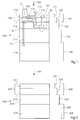
- FIG. 1 shows a schematic cross section of the layer structure or the layer sequence and the functional zones of a printing plate 100 according to the invention, which from the top with electromagnetic energy, preferably in the form of laser radiation 102 (eg. Infrared radiation in the wavelength range of 830 nanometers) is applied.
- electromagnetic energy preferably in the form of laser radiation 102 (eg. Infrared radiation in the wavelength range of 830 nanometers) is applied.
- the printing form is formed by a printing cylinder surface, it is possible to dispense with the support 118 or, in other words, the printing cylinder itself can form the support 118. This also applies correspondingly in the other embodiments.
- the information layer 110 and the absorption layer 112 together form an antireflection layer 150 or an antireflection system 150 at least for the introduced radiation, ie for the corresponding wavelength, such that the radiation penetrates into the absorption layer 112 substantially without reflection.
- the layer thicknesses and the respective refractive indices are matched to one another.
- the layer thickness of the cover layer is preferably n ⁇ / 4, where n is an odd-numbered, integer preferably greater than 5.
- the refractive index of the information layer 110 lies between the refractive index of air and the refractive index of the layer lying below the information layer 110 and is preferably the root of the refractive index of the layer located below the information layer 110.
- the functional zones of the printing form 100 are represented by lines. Like from the FIG. 1 It can be seen that the functional zones can on the one hand coincide with individual layers of the layer structure and on the other hand comprise several layers (in whole or in part). It can also be seen that individual layers can also be assigned to several functional zones.
- FIG. 1 also shows the energy flow.
- the energy 170 in the form of electromagnetic radiation 102 irradiated onto the layer structure of the printing forme 100 is lost only to a slight extent by reflection 172 (reflection loss 172), preferably less than about 20%, so that initially only this part 172 of the incident energy 170 is not lost for the reflection actual imaging process is available.
- the heat energy 190 coupled in the absorption zone 122 is lost only to a slight extent by transmission 174 (transmission loss 174) into the carrier 118, preferably less than about 5%, in particular 1%, and this part 174 of the incident energy 170 likewise does not stand available for the actual imaging process.
- the predominant portion 176 (deposited thermal energy 176) of the coupled-in thermal energy 190 is absorbed by the buffer zone 124 arranged at least partially lower than the absorption zone 122 via heat conduction 178 and as a buffered thermal energy 180 in time and spatially buffered. From the buffer zone 124, the heat energy 180 passes, with a time delay, via heat conduction 182 back into the absorption zone 122 and the information zone 120, where the heat energy is required for the actual (physical or chemical) imaging process.
- FIG. 2 shows a schematic cross section of the layer structure or the layer sequence of a further printing form 200 according to the invention, which is acted upon from above with laser radiation 202, preferably in the infrared region, for imaging.
- the information layer 110 and the absorption layer 112 together form an antireflective layer 250 or antireflective system 250 at least for the introduced radiation 202, d. H. for the corresponding wavelength, such that the radiation penetrates into the absorption layer 212 substantially without reflection.
- FIG. 3 a further embodiment of the invention for a with respect to the degree of utilization of the introduced radiation 302 optimized printing plate 300 is shown with amphiphilic molecules.
- a carrier made of sheet metal, preferably steel or aluminum sheet, wherein the sheet may preferably be provided with a polyimide layer which is about 10 or only about 5 micrometers thick (for example by gluing on) ,
- An optionally applied on the absorption layer 312, usable as an information layer and with the absorption layer 312 an antireflection layer 350 forming further layer may be exemplified as a TiO 2 layer which reduces the reflection of the incident light by destructive interference (example: refractive index of TiO 2 is 1.8, wavelength is 900 nanometers, thickness is 125 nanometers).
- titanium (Ti) its oxides or nitrides may also be present in layer 312 (or in the additional antireflective coating) zirconium (Zr), manganese (Mn), aluminum (Al), chromium (Cr), tantalum (Ta), tin (Sn), zinc (Zn) and iron (Fe), their oxides or nitrides or mixtures are used.
- a very thin buffer layer 314 may be provided, which also has the task of protecting the layer interface between the polyimide film 318 and its coating from excessive thermal stress.
- amphiphilic molecules eg, stearic phosphonic acid
- the layer 312 is also very resistant to abrasion, which benefits the stability in the printing process.
- the polyimide substrate provides effective thermal isolation so that the coupled thermal energy is used essentially to heat an area only 600 nanometers thick at the surface. As a result, reaching the Becularungstemperatur is already possible with low laser power.
- FIG. 3 In addition to the layer sequence of the printing form 300, again the functional zones are represented by lines: an information zone 320, an absorption zone 322, a buffer zone 324, an isolation zone 326, a carrier zone 328 and an antireflection zone 360
- FIG. 4 shows a further embodiment of the invention for a printing plate 400, which is based on the principle of thermal mixing and is applied during a Bericeungsreaes with laser radiation 402 corresponding to the image information.
- the polymer surface is inherently hydrophobic and can be treated by treatment with chemicals, e.g. B. with KMnO4 or by plasma or ultraviolet treatment over a large area hydrophilic, the penetration depth of such processes typically does not exceed 10 nanometers.
- the polymer is then melted, non-hydrophilized, deeper molecules and hydrophilized molecules of the treated surface mix together.
- the proportion of hydrophilized molecules on the surface is as large as their proportion in the polymer layer as a whole, d. H. at z. B. 1 nanometer hydrophilization depth and 5 microns layer thickness only 0.2 per thousand.
- the solidified polymer layer thus again has its hydrophobic character.
- the previously hydrophilized printing form can be effectively imaged, i. H. be spotwise hydrophobic by melting and thermal mixing.
- the thermal energy is conducted by conduction to the surface of the printing plate 400 (ie the polymer surface), also a larger volume (buffer layer 414 and polymer layer 410) heated, and the enthalpy of fusion must be applied, the storage of significantly more energy is necessary as in the embodiment of FIG. 3 , This fact is accommodated by a thicker buffer layer 414 in this embodiment.
- the functional zones of the printing form 400 are represented by lines: an information zone 420, an absorption zone 422, a buffer zone 424, an isolation zone 426 and a carrier zone 428.
- the invention can also be used in printing processes in which the printed image is written by laser radiation in a full-surface ink layer on the printing form.
- the initially hard ink layer is liquefied at the Becularungsticianen and by a given given solidification delay of the ink, the printed image can be transferred to a substrate.
- the printing form has a carrier layer (corresponding to 118 in FIG. 1 ), an insulating layer (corresponding to 116 in FIG. 1 ), wherein the carrier and the insulating layer may also form a unit (corresponding to 218 in FIG FIG. 2 ), and a buffer layer (corresponding to 114 in FIG FIG. 1 ) on.
- the absorption layer (corresponding to 112 in FIG. 1 ) and also the information layer (corresponding to 110 in FIG. 1 ) are formed by the applied color layer.
- the absorption layer can also be arranged below the throat level.
Landscapes
- Engineering & Computer Science (AREA)
- Manufacturing & Machinery (AREA)
- Printing Plates And Materials Therefor (AREA)
- Materials For Photolithography (AREA)
- Photosensitive Polymer And Photoresist Processing (AREA)
- Laminated Bodies (AREA)
Claims (6)
- Forme d'impression avec plusieurs zones de fonction étendues, qui comprennent au moins une zone d'information (110, 210, 312, 410) et une zone d'absorption (112, 212, 312, 412) pour l'énergie d'un rayonnement (102, 202, 302, 402) et en ce qu'une zone tampon (114, 214, 314, 414) au moins partiellement différente de la zone d'absorption (112, 212, 312, 412) laquelle absorbe l'énergie de la zone d'absorption (112, 212, 312, 412) et transmet l'énergie à la zone d'information (110, 210, 312, 410) et en ce que la zone tampon (114, 214, 314, 414) est plus épaisse que la zone d'absorption (112, 212, 312, 412), présente en particulier une épaisseur d'environ 0,5 à 10 micromètres ou une épaisseur d'environ 1 micromètre et en ce qu'une zone d'isolation thermique (116, 218, 318, 418) est prévue au moins partiellement en dessous de la zone d'absorption (112, 212, 312, 412) et que la forme d'impression (100, 200, 300, 400) présente un support (118, 218, 318, 418),
caractérisée en ce
qu'une zone antireflet (160, 260 360) est prévue pour le rayonnement (102, 202, 302) et en ce que la zone antireflet (160, 260 360) est constituée par la zone d'information (110, 210, 312, 410) modifiable en fonction d'une information d'image correspondante et par la zone d'absorption (112, 212, 312, 412). - Forme d'impression selon la revendication 1
caractérisée en ce
que la zone tampon (114, 214, 314, 414) est réalisée comme une zone tampon adaptée. - Forme d'impression selon l'une des revendications précédentes,
caractérisée en ce
que la zone d'information (110, 210, 312, 410) modifiable en fonction d'une information d'image correspondante est réalisée comme une zone (110, 210, 312, 410) porteuse ou apte à supporter une information d'image externe. - Forme d'impression selon l'une des revendications 1 ou 2,
caractérisée en ce
que la zone d'information (110, 210, 312, 410) modifiable en fonction d'une information d'image correspondante est réalisée comme une couche d'encre (312) ou une couche de polymère (312) porteuse ou apte à supporter une information d'image externe. - Forme d'impression selon l'une des revendications précédentes,
caractérisée en ce
qu'au moins la zone d'absorption (112, 212, 312, 412) et la zone tampon (114, 214, 314, 414) sont réalisées comme des couches séparées. - Machine d'impression avec au moins un cylindre d'impression,
caractérisée en ce
que le cylindre d'impression (118) est muni d'une forme d'impression (100, 200, 300, 400) selon l'une des revendications précédentes ou en ce que le cylindre d'impression (118) constitue une forme d'impression (100, 200, 300, 400) selon l'une des revendications précédentes.
Applications Claiming Priority (2)
| Application Number | Priority Date | Filing Date | Title |
|---|---|---|---|
| DE102004007600 | 2004-02-17 | ||
| DE102004007600A DE102004007600A1 (de) | 2004-02-17 | 2004-02-17 | Druckform mit mehreren flächigen Funktionszonen |
Publications (3)
| Publication Number | Publication Date |
|---|---|
| EP1563992A2 EP1563992A2 (fr) | 2005-08-17 |
| EP1563992A3 EP1563992A3 (fr) | 2006-01-11 |
| EP1563992B1 true EP1563992B1 (fr) | 2016-09-07 |
Family
ID=34684082
Family Applications (1)
| Application Number | Title | Priority Date | Filing Date |
|---|---|---|---|
| EP05100599.9A Expired - Lifetime EP1563992B1 (fr) | 2004-02-17 | 2005-01-31 | Plaque d'impression avec plusieurs couches fonctionelles |
Country Status (7)
| Country | Link |
|---|---|
| US (1) | US7704590B2 (fr) |
| EP (1) | EP1563992B1 (fr) |
| JP (1) | JP4904003B2 (fr) |
| CN (1) | CN100500450C (fr) |
| CA (1) | CA2496342A1 (fr) |
| DE (1) | DE102004007600A1 (fr) |
| IL (1) | IL166910A (fr) |
Families Citing this family (11)
| Publication number | Priority date | Publication date | Assignee | Title |
|---|---|---|---|---|
| US9463643B2 (en) | 2006-02-21 | 2016-10-11 | R.R. Donnelley & Sons Company | Apparatus and methods for controlling application of a substance to a substrate |
| US8869698B2 (en) | 2007-02-21 | 2014-10-28 | R.R. Donnelley & Sons Company | Method and apparatus for transferring a principal substance |
| US8733248B2 (en) | 2006-02-21 | 2014-05-27 | R.R. Donnelley & Sons Company | Method and apparatus for transferring a principal substance and printing system |
| US8967044B2 (en) * | 2006-02-21 | 2015-03-03 | R.R. Donnelley & Sons, Inc. | Apparatus for applying gating agents to a substrate and image generation kit |
| MX2008010723A (es) * | 2006-02-21 | 2009-01-26 | Moore Wallace North Am Inc | Sistema y metodos de impresion variable a alta velocidad. |
| WO2009025814A1 (fr) | 2007-08-20 | 2009-02-26 | Rr Donnelley | Procédé et dispositif pour l'impression par jet d'encre |
| US9701120B2 (en) | 2007-08-20 | 2017-07-11 | R.R. Donnelley & Sons Company | Compositions compatible with jet printing and methods therefor |
| DE102012013302A1 (de) | 2011-08-11 | 2013-02-14 | Heidelberger Druckmaschinen Ag | Druckform |
| DE102012021983A1 (de) | 2012-06-15 | 2013-12-19 | Heidelberger Druckmaschinen Ag | Verfahren zum indirekten Auftragen von Druckflüssigkeit auf einen Bedruckstoff |
| US10153324B2 (en) * | 2016-09-02 | 2018-12-11 | Arizona Board Of Regents On Behalf Of Arizona State University | Low-voltage charge-coupled devices with a heterostructure charge-storage well |
| CN110588141A (zh) * | 2019-09-03 | 2019-12-20 | 天津保创印刷材料有限公司 | 印刷版及其制备工艺 |
Family Cites Families (17)
| Publication number | Priority date | Publication date | Assignee | Title |
|---|---|---|---|---|
| US5322763A (en) * | 1992-05-06 | 1994-06-21 | E. I. Du Pont De Nemours And Company | Process for making metal ledge on stencil screen |
| USRE35512F1 (en) * | 1992-07-20 | 1998-08-04 | Presstek Inc | Lithographic printing members for use with laser-discharge imaging |
| US5351617A (en) * | 1992-07-20 | 1994-10-04 | Presstek, Inc. | Method for laser-discharge imaging a printing plate |
| US5570636A (en) * | 1995-05-04 | 1996-11-05 | Presstek, Inc. | Laser-imageable lithographic printing members with dimensionally stable base supports |
| US5868074A (en) * | 1995-05-08 | 1999-02-09 | Flex Products, Inc. | Laser imageable direct-write printing member |
| US5632204A (en) | 1995-07-27 | 1997-05-27 | Presstek, Inc. | Thin-metal lithographic printing members with integral reflective layers |
| US5783364A (en) * | 1996-08-20 | 1998-07-21 | Presstek, Inc. | Thin-film imaging recording constructions incorporating metallic inorganic layers and optical interference structures |
| EP0847853B1 (fr) * | 1996-11-14 | 2001-01-24 | Kodak Polychrome Graphics LLC | Plaque lithographique sans développement |
| DE59712866D1 (de) * | 1997-11-03 | 2007-09-06 | Stork Prints Austria Gmbh | Verfahren zum Herstellen einer Druckform |
| US6073559A (en) | 1998-09-11 | 2000-06-13 | Presstek, Inc. | Lithographic imaging with constructions having inorganic oleophilic layers |
| DE10138772A1 (de) | 2000-09-07 | 2002-03-28 | Heidelberger Druckmasch Ag | Wiederbeschreibbare Druckform zum Drucken mit schmelzbarer Druckfarbe |
| JP2002082429A (ja) | 2000-09-08 | 2002-03-22 | Fuji Photo Film Co Ltd | ネガ型画像記録材料 |
| US6521391B1 (en) * | 2000-09-14 | 2003-02-18 | Alcoa Inc. | Printing plate |
| DE10115435B8 (de) * | 2001-03-29 | 2007-02-08 | Maschinenfabrik Wifag | Verfahren zur Erzeugung eines Druckbilds und/oder zur Löschung eines Druckbilds einer Nassoffset-Druckform mit fotothermisch veränderbarem Material |
| DE10227054B4 (de) | 2002-06-17 | 2013-01-03 | Heidelberger Druckmaschinen Ag | Wiederverwendbare Druckform, Druckwerk und Druckmaschine damit sowie Verfahren zur Bebilderung der Druckform |
| DE10354341A1 (de) | 2002-11-21 | 2004-06-03 | Heidelberger Druckmaschinen Ag | Verfahren und Einrichtung zum Strukturieren einer Druckformoberfläche |
| JP2007531019A (ja) * | 2004-03-26 | 2007-11-01 | プレステク,インコーポレイテッド | 溶解度変化層を有する印刷部材及び関連する方法 |
-
2004
- 2004-02-17 DE DE102004007600A patent/DE102004007600A1/de not_active Ceased
-
2005
- 2005-01-31 EP EP05100599.9A patent/EP1563992B1/fr not_active Expired - Lifetime
- 2005-02-09 CA CA002496342A patent/CA2496342A1/fr not_active Abandoned
- 2005-02-15 US US11/058,039 patent/US7704590B2/en not_active Expired - Fee Related
- 2005-02-15 IL IL166910A patent/IL166910A/en not_active IP Right Cessation
- 2005-02-17 JP JP2005041071A patent/JP4904003B2/ja not_active Expired - Fee Related
- 2005-02-17 CN CNB2005100090668A patent/CN100500450C/zh not_active Expired - Fee Related
Non-Patent Citations (1)
| Title |
|---|
| None * |
Also Published As
| Publication number | Publication date |
|---|---|
| IL166910A (en) | 2007-06-17 |
| CA2496342A1 (fr) | 2005-08-17 |
| JP2005231370A (ja) | 2005-09-02 |
| EP1563992A2 (fr) | 2005-08-17 |
| JP4904003B2 (ja) | 2012-03-28 |
| CN100500450C (zh) | 2009-06-17 |
| CN1657313A (zh) | 2005-08-24 |
| US7704590B2 (en) | 2010-04-27 |
| EP1563992A3 (fr) | 2006-01-11 |
| DE102004007600A1 (de) | 2005-09-01 |
| US20050181187A1 (en) | 2005-08-18 |
Similar Documents
| Publication | Publication Date | Title |
|---|---|---|
| DE69733906T2 (de) | Dünnfilm-Bildaufzeichnungskonstruktionen mit anorganischen Metallschichten und optischen Interferenz-Strukturen | |
| DE69514568T2 (de) | Flachdruckplatten zur Bebilderung mittels Laserbestrahlung | |
| EP1563992B1 (fr) | Plaque d'impression avec plusieurs couches fonctionelles | |
| DE69914649T2 (de) | Verfahren zur lithographischen Aufzeichnung mit weniger Leistungsfähigkeitsverschlechterung durch Abstoffe | |
| DE60024190T2 (de) | Infrarotlaser-bebilderbare Flachdruckplatte und Verfahren zu ihrer Herstellung | |
| DE3636129C2 (fr) | ||
| DE69604258T2 (de) | Flachdruckverfahren | |
| EP0559069A1 (fr) | Document de valeur | |
| DE112012003902B4 (de) | Verfahren zur Herstellung einer durch Abblättern abzutrennenden Verbundstruktur, zugehörige Verbundstruktur und Verfahren zum Trennen derselben | |
| EP1473154A2 (fr) | Méthode d'impression et machine d'impression | |
| EP1151857A2 (fr) | Formation et effacement d'un image d'une façon contrôlée sur une forme d'impression en titane métallique | |
| DE69731969T2 (de) | Flachdruckplatten-vorlaüfer mit einer mit laserbestrahlung bebildbarer mehrschichtfolie mit optischen hohlraum | |
| DE69908261T2 (de) | Lithographisches verfahren mit anorganisch-organischen mischungen enthaltenden schichten | |
| DE10360108A1 (de) | Herstellung einer wiederverwendbaren Druckform | |
| EP2191976A2 (fr) | Procédé de marquage ou d'inscription d'une pièce à usiner | |
| DE102006019118B4 (de) | Bauelement mit optischer Markierung und Verfahren zur Herstellung | |
| DE69911791T2 (de) | Verfahren zum beschriften eines laminierten films | |
| DE69613919T2 (de) | Verfahren zur Herstellung einer Flachdruckplatte, die kein Feuchtwasser erfordert | |
| DE69926211T2 (de) | Flachdruckplatte und Verfahren zu seiner Herstellung, das Laserstrahlung verwendet | |
| DE10115435B4 (de) | Verfahren zur Erzeugung eines Druckbilds und/oder zur Löschung eines Druckbilds einer Nassoffset-Druckform mit fofothermisch veränderbarem Material | |
| DE69917126T2 (de) | Vorläufer für eine Flachdruckplatte sowie Verfahren zu deren Herstellung | |
| DE69907580T2 (de) | Verfahren zur lithographischen Aufzeichnung mit weniger Leistungsfähigkeitsverschlechterung durch Abstoffe | |
| WO2008092650A2 (fr) | Procédé et film de marquage pour le transfert sélectif d'au moins une couche fonctionnelle sur un support | |
| DE10017614B4 (de) | Verfahren zur Herstellung einer dielektrischen Reflexionsmaske | |
| DE60113898T2 (de) | Verfahren zur ausbildung eines ablationsbildes |
Legal Events
| Date | Code | Title | Description |
|---|---|---|---|
| PUAI | Public reference made under article 153(3) epc to a published international application that has entered the european phase |
Free format text: ORIGINAL CODE: 0009012 |
|
| AK | Designated contracting states |
Kind code of ref document: A2 Designated state(s): AT BE BG CH CY CZ DE DK EE ES FI FR GB GR HU IE IS IT LI LT LU MC NL PL PT RO SE SI SK TR |
|
| AX | Request for extension of the european patent |
Extension state: AL BA HR LV MK YU |
|
| PUAL | Search report despatched |
Free format text: ORIGINAL CODE: 0009013 |
|
| AK | Designated contracting states |
Kind code of ref document: A3 Designated state(s): AT BE BG CH CY CZ DE DK EE ES FI FR GB GR HU IE IS IT LI LT LU MC NL PL PT RO SE SI SK TR |
|
| AX | Request for extension of the european patent |
Extension state: AL BA HR LV MK YU |
|
| RIC1 | Information provided on ipc code assigned before grant |
Ipc: B41N 1/08 20060101ALI20051121BHEP Ipc: B41N 1/14 20060101ALI20051121BHEP Ipc: B41C 1/10 20060101AFI20050602BHEP |
|
| 17P | Request for examination filed |
Effective date: 20060711 |
|
| AKX | Designation fees paid |
Designated state(s): AT BE BG CH CY CZ DE DK EE ES FI FR GB GR HU IE IS IT LI LT LU MC NL PL PT RO SE SI SK TR |
|
| 17Q | First examination report despatched |
Effective date: 20061009 |
|
| APBK | Appeal reference recorded |
Free format text: ORIGINAL CODE: EPIDOSNREFNE |
|
| APBN | Date of receipt of notice of appeal recorded |
Free format text: ORIGINAL CODE: EPIDOSNNOA2E |
|
| APBR | Date of receipt of statement of grounds of appeal recorded |
Free format text: ORIGINAL CODE: EPIDOSNNOA3E |
|
| APAF | Appeal reference modified |
Free format text: ORIGINAL CODE: EPIDOSCREFNE |
|
| APBX | Invitation to file observations in appeal sent |
Free format text: ORIGINAL CODE: EPIDOSNOBA2E |
|
| APBZ | Receipt of observations in appeal recorded |
Free format text: ORIGINAL CODE: EPIDOSNOBA4E |
|
| APBT | Appeal procedure closed |
Free format text: ORIGINAL CODE: EPIDOSNNOA9E |
|
| GRAP | Despatch of communication of intention to grant a patent |
Free format text: ORIGINAL CODE: EPIDOSNIGR1 |
|
| INTG | Intention to grant announced |
Effective date: 20160601 |
|
| GRAS | Grant fee paid |
Free format text: ORIGINAL CODE: EPIDOSNIGR3 |
|
| GRAA | (expected) grant |
Free format text: ORIGINAL CODE: 0009210 |
|
| AK | Designated contracting states |
Kind code of ref document: B1 Designated state(s): AT BE BG CH CY CZ DE DK EE ES FI FR GB GR HU IE IS IT LI LT LU MC NL PL PT RO SE SI SK TR |
|
| REG | Reference to a national code |
Ref country code: GB Ref legal event code: FG4D Free format text: NOT ENGLISH |
|
| REG | Reference to a national code |
Ref country code: CH Ref legal event code: EP |
|
| REG | Reference to a national code |
Ref country code: IE Ref legal event code: FG4D Free format text: LANGUAGE OF EP DOCUMENT: GERMAN |
|
| REG | Reference to a national code |
Ref country code: AT Ref legal event code: REF Ref document number: 826469 Country of ref document: AT Kind code of ref document: T Effective date: 20161015 |
|
| REG | Reference to a national code |
Ref country code: DE Ref legal event code: R096 Ref document number: 502005015356 Country of ref document: DE |
|
| REG | Reference to a national code |
Ref country code: LT Ref legal event code: MG4D |
|
| REG | Reference to a national code |
Ref country code: NL Ref legal event code: MP Effective date: 20160907 |
|
| PG25 | Lapsed in a contracting state [announced via postgrant information from national office to epo] |
Ref country code: LT Free format text: LAPSE BECAUSE OF FAILURE TO SUBMIT A TRANSLATION OF THE DESCRIPTION OR TO PAY THE FEE WITHIN THE PRESCRIBED TIME-LIMIT Effective date: 20160907 Ref country code: FI Free format text: LAPSE BECAUSE OF FAILURE TO SUBMIT A TRANSLATION OF THE DESCRIPTION OR TO PAY THE FEE WITHIN THE PRESCRIBED TIME-LIMIT Effective date: 20160907 |
|
| PG25 | Lapsed in a contracting state [announced via postgrant information from national office to epo] |
Ref country code: NL Free format text: LAPSE BECAUSE OF FAILURE TO SUBMIT A TRANSLATION OF THE DESCRIPTION OR TO PAY THE FEE WITHIN THE PRESCRIBED TIME-LIMIT Effective date: 20160907 Ref country code: SE Free format text: LAPSE BECAUSE OF FAILURE TO SUBMIT A TRANSLATION OF THE DESCRIPTION OR TO PAY THE FEE WITHIN THE PRESCRIBED TIME-LIMIT Effective date: 20160907 Ref country code: GR Free format text: LAPSE BECAUSE OF FAILURE TO SUBMIT A TRANSLATION OF THE DESCRIPTION OR TO PAY THE FEE WITHIN THE PRESCRIBED TIME-LIMIT Effective date: 20161208 Ref country code: ES Free format text: LAPSE BECAUSE OF FAILURE TO SUBMIT A TRANSLATION OF THE DESCRIPTION OR TO PAY THE FEE WITHIN THE PRESCRIBED TIME-LIMIT Effective date: 20160907 |
|
| PG25 | Lapsed in a contracting state [announced via postgrant information from national office to epo] |
Ref country code: RO Free format text: LAPSE BECAUSE OF FAILURE TO SUBMIT A TRANSLATION OF THE DESCRIPTION OR TO PAY THE FEE WITHIN THE PRESCRIBED TIME-LIMIT Effective date: 20160907 Ref country code: EE Free format text: LAPSE BECAUSE OF FAILURE TO SUBMIT A TRANSLATION OF THE DESCRIPTION OR TO PAY THE FEE WITHIN THE PRESCRIBED TIME-LIMIT Effective date: 20160907 |
|
| PG25 | Lapsed in a contracting state [announced via postgrant information from national office to epo] |
Ref country code: PL Free format text: LAPSE BECAUSE OF FAILURE TO SUBMIT A TRANSLATION OF THE DESCRIPTION OR TO PAY THE FEE WITHIN THE PRESCRIBED TIME-LIMIT Effective date: 20160907 Ref country code: BG Free format text: LAPSE BECAUSE OF FAILURE TO SUBMIT A TRANSLATION OF THE DESCRIPTION OR TO PAY THE FEE WITHIN THE PRESCRIBED TIME-LIMIT Effective date: 20161207 Ref country code: IS Free format text: LAPSE BECAUSE OF FAILURE TO SUBMIT A TRANSLATION OF THE DESCRIPTION OR TO PAY THE FEE WITHIN THE PRESCRIBED TIME-LIMIT Effective date: 20170107 Ref country code: BE Free format text: LAPSE BECAUSE OF NON-PAYMENT OF DUE FEES Effective date: 20170131 Ref country code: PT Free format text: LAPSE BECAUSE OF FAILURE TO SUBMIT A TRANSLATION OF THE DESCRIPTION OR TO PAY THE FEE WITHIN THE PRESCRIBED TIME-LIMIT Effective date: 20170109 Ref country code: SK Free format text: LAPSE BECAUSE OF FAILURE TO SUBMIT A TRANSLATION OF THE DESCRIPTION OR TO PAY THE FEE WITHIN THE PRESCRIBED TIME-LIMIT Effective date: 20160907 Ref country code: CZ Free format text: LAPSE BECAUSE OF FAILURE TO SUBMIT A TRANSLATION OF THE DESCRIPTION OR TO PAY THE FEE WITHIN THE PRESCRIBED TIME-LIMIT Effective date: 20160907 |
|
| REG | Reference to a national code |
Ref country code: DE Ref legal event code: R097 Ref document number: 502005015356 Country of ref document: DE |
|
| PG25 | Lapsed in a contracting state [announced via postgrant information from national office to epo] |
Ref country code: IT Free format text: LAPSE BECAUSE OF FAILURE TO SUBMIT A TRANSLATION OF THE DESCRIPTION OR TO PAY THE FEE WITHIN THE PRESCRIBED TIME-LIMIT Effective date: 20160907 |
|
| PLBE | No opposition filed within time limit |
Free format text: ORIGINAL CODE: 0009261 |
|
| STAA | Information on the status of an ep patent application or granted ep patent |
Free format text: STATUS: NO OPPOSITION FILED WITHIN TIME LIMIT |
|
| PG25 | Lapsed in a contracting state [announced via postgrant information from national office to epo] |
Ref country code: DK Free format text: LAPSE BECAUSE OF FAILURE TO SUBMIT A TRANSLATION OF THE DESCRIPTION OR TO PAY THE FEE WITHIN THE PRESCRIBED TIME-LIMIT Effective date: 20160907 |
|
| 26N | No opposition filed |
Effective date: 20170608 |
|
| PG25 | Lapsed in a contracting state [announced via postgrant information from national office to epo] |
Ref country code: SI Free format text: LAPSE BECAUSE OF FAILURE TO SUBMIT A TRANSLATION OF THE DESCRIPTION OR TO PAY THE FEE WITHIN THE PRESCRIBED TIME-LIMIT Effective date: 20160907 |
|
| REG | Reference to a national code |
Ref country code: CH Ref legal event code: PL |
|
| GBPC | Gb: european patent ceased through non-payment of renewal fee |
Effective date: 20170131 |
|
| PG25 | Lapsed in a contracting state [announced via postgrant information from national office to epo] |
Ref country code: MC Free format text: LAPSE BECAUSE OF FAILURE TO SUBMIT A TRANSLATION OF THE DESCRIPTION OR TO PAY THE FEE WITHIN THE PRESCRIBED TIME-LIMIT Effective date: 20160907 |
|
| REG | Reference to a national code |
Ref country code: FR Ref legal event code: ST Effective date: 20170929 |
|
| PG25 | Lapsed in a contracting state [announced via postgrant information from national office to epo] |
Ref country code: LI Free format text: LAPSE BECAUSE OF NON-PAYMENT OF DUE FEES Effective date: 20170131 Ref country code: CH Free format text: LAPSE BECAUSE OF NON-PAYMENT OF DUE FEES Effective date: 20170131 Ref country code: FR Free format text: LAPSE BECAUSE OF NON-PAYMENT OF DUE FEES Effective date: 20170131 |
|
| REG | Reference to a national code |
Ref country code: IE Ref legal event code: MM4A |
|
| PG25 | Lapsed in a contracting state [announced via postgrant information from national office to epo] |
Ref country code: GB Free format text: LAPSE BECAUSE OF NON-PAYMENT OF DUE FEES Effective date: 20170131 Ref country code: LU Free format text: LAPSE BECAUSE OF NON-PAYMENT OF DUE FEES Effective date: 20170131 |
|
| REG | Reference to a national code |
Ref country code: BE Ref legal event code: MM Effective date: 20170131 |
|
| PG25 | Lapsed in a contracting state [announced via postgrant information from national office to epo] |
Ref country code: IE Free format text: LAPSE BECAUSE OF NON-PAYMENT OF DUE FEES Effective date: 20170131 |
|
| REG | Reference to a national code |
Ref country code: AT Ref legal event code: MM01 Ref document number: 826469 Country of ref document: AT Kind code of ref document: T Effective date: 20170131 |
|
| PG25 | Lapsed in a contracting state [announced via postgrant information from national office to epo] |
Ref country code: AT Free format text: LAPSE BECAUSE OF NON-PAYMENT OF DUE FEES Effective date: 20170131 |
|
| PG25 | Lapsed in a contracting state [announced via postgrant information from national office to epo] |
Ref country code: HU Free format text: LAPSE BECAUSE OF FAILURE TO SUBMIT A TRANSLATION OF THE DESCRIPTION OR TO PAY THE FEE WITHIN THE PRESCRIBED TIME-LIMIT; INVALID AB INITIO Effective date: 20050131 |
|
| PG25 | Lapsed in a contracting state [announced via postgrant information from national office to epo] |
Ref country code: CY Free format text: LAPSE BECAUSE OF NON-PAYMENT OF DUE FEES Effective date: 20160907 |
|
| PG25 | Lapsed in a contracting state [announced via postgrant information from national office to epo] |
Ref country code: TR Free format text: LAPSE BECAUSE OF FAILURE TO SUBMIT A TRANSLATION OF THE DESCRIPTION OR TO PAY THE FEE WITHIN THE PRESCRIBED TIME-LIMIT Effective date: 20160907 |
|
| PGFP | Annual fee paid to national office [announced via postgrant information from national office to epo] |
Ref country code: DE Payment date: 20200131 Year of fee payment: 16 |
|
| REG | Reference to a national code |
Ref country code: DE Ref legal event code: R119 Ref document number: 502005015356 Country of ref document: DE |
|
| PG25 | Lapsed in a contracting state [announced via postgrant information from national office to epo] |
Ref country code: DE Free format text: LAPSE BECAUSE OF NON-PAYMENT OF DUE FEES Effective date: 20210803 |