EP1563290B1 - Qualitätsprüfungsverfahren mittels frequenzveränderlicher anregungsschwingungen - Google Patents
Qualitätsprüfungsverfahren mittels frequenzveränderlicher anregungsschwingungen Download PDFInfo
- Publication number
- EP1563290B1 EP1563290B1 EP03769407A EP03769407A EP1563290B1 EP 1563290 B1 EP1563290 B1 EP 1563290B1 EP 03769407 A EP03769407 A EP 03769407A EP 03769407 A EP03769407 A EP 03769407A EP 1563290 B1 EP1563290 B1 EP 1563290B1
- Authority
- EP
- European Patent Office
- Prior art keywords
- frequency
- resonance
- interval
- unit
- frequency range
- Prior art date
- Legal status (The legal status is an assumption and is not a legal conclusion. Google has not performed a legal analysis and makes no representation as to the accuracy of the status listed.)
- Expired - Lifetime
Links
- 238000003908 quality control method Methods 0.000 title 1
- 238000000034 method Methods 0.000 claims abstract description 22
- 230000010355 oscillation Effects 0.000 claims abstract description 17
- 238000012360 testing method Methods 0.000 abstract description 4
- 238000011156 evaluation Methods 0.000 abstract description 2
- 238000005259 measurement Methods 0.000 description 24
- 230000001133 acceleration Effects 0.000 description 17
- 230000003595 spectral effect Effects 0.000 description 5
- 238000007689 inspection Methods 0.000 description 4
- 238000012372 quality testing Methods 0.000 description 4
- 238000010276 construction Methods 0.000 description 3
- 238000010009 beating Methods 0.000 description 2
- 230000007423 decrease Effects 0.000 description 2
- 238000011161 development Methods 0.000 description 2
- 230000005284 excitation Effects 0.000 description 2
- 230000000737 periodic effect Effects 0.000 description 2
- 238000010998 test method Methods 0.000 description 2
- 230000000712 assembly Effects 0.000 description 1
- 238000000429 assembly Methods 0.000 description 1
- 230000002238 attenuated effect Effects 0.000 description 1
- 230000035559 beat frequency Effects 0.000 description 1
- 230000003247 decreasing effect Effects 0.000 description 1
- 238000001514 detection method Methods 0.000 description 1
- 238000011835 investigation Methods 0.000 description 1
- 238000004519 manufacturing process Methods 0.000 description 1
- 238000001303 quality assessment method Methods 0.000 description 1
- 239000007787 solid Substances 0.000 description 1
- 238000001228 spectrum Methods 0.000 description 1
- 239000000758 substrate Substances 0.000 description 1
Images

Classifications
-
- G—PHYSICS
- G01—MEASURING; TESTING
- G01H—MEASUREMENT OF MECHANICAL VIBRATIONS OR ULTRASONIC, SONIC OR INFRASONIC WAVES
- G01H1/00—Measuring characteristics of vibrations in solids by using direct conduction to the detector
- G01H1/003—Measuring characteristics of vibrations in solids by using direct conduction to the detector of rotating machines
-
- G—PHYSICS
- G01—MEASURING; TESTING
- G01N—INVESTIGATING OR ANALYSING MATERIALS BY DETERMINING THEIR CHEMICAL OR PHYSICAL PROPERTIES
- G01N29/00—Investigating or analysing materials by the use of ultrasonic, sonic or infrasonic waves; Visualisation of the interior of objects by transmitting ultrasonic or sonic waves through the object
- G01N29/04—Analysing solids
- G01N29/11—Analysing solids by measuring attenuation of acoustic waves
-
- G—PHYSICS
- G01—MEASURING; TESTING
- G01N—INVESTIGATING OR ANALYSING MATERIALS BY DETERMINING THEIR CHEMICAL OR PHYSICAL PROPERTIES
- G01N29/00—Investigating or analysing materials by the use of ultrasonic, sonic or infrasonic waves; Visualisation of the interior of objects by transmitting ultrasonic or sonic waves through the object
- G01N29/04—Analysing solids
- G01N29/12—Analysing solids by measuring frequency or resonance of acoustic waves
-
- G—PHYSICS
- G01—MEASURING; TESTING
- G01N—INVESTIGATING OR ANALYSING MATERIALS BY DETERMINING THEIR CHEMICAL OR PHYSICAL PROPERTIES
- G01N29/00—Investigating or analysing materials by the use of ultrasonic, sonic or infrasonic waves; Visualisation of the interior of objects by transmitting ultrasonic or sonic waves through the object
- G01N29/14—Investigating or analysing materials by the use of ultrasonic, sonic or infrasonic waves; Visualisation of the interior of objects by transmitting ultrasonic or sonic waves through the object using acoustic emission techniques
-
- G—PHYSICS
- G01—MEASURING; TESTING
- G01N—INVESTIGATING OR ANALYSING MATERIALS BY DETERMINING THEIR CHEMICAL OR PHYSICAL PROPERTIES
- G01N29/00—Investigating or analysing materials by the use of ultrasonic, sonic or infrasonic waves; Visualisation of the interior of objects by transmitting ultrasonic or sonic waves through the object
- G01N29/34—Generating the ultrasonic, sonic or infrasonic waves, e.g. electronic circuits specially adapted therefor
- G01N29/348—Generating the ultrasonic, sonic or infrasonic waves, e.g. electronic circuits specially adapted therefor with frequency characteristics, e.g. single frequency signals, chirp signals
-
- G—PHYSICS
- G01—MEASURING; TESTING
- G01N—INVESTIGATING OR ANALYSING MATERIALS BY DETERMINING THEIR CHEMICAL OR PHYSICAL PROPERTIES
- G01N29/00—Investigating or analysing materials by the use of ultrasonic, sonic or infrasonic waves; Visualisation of the interior of objects by transmitting ultrasonic or sonic waves through the object
- G01N29/36—Detecting the response signal, e.g. electronic circuits specially adapted therefor
- G01N29/42—Detecting the response signal, e.g. electronic circuits specially adapted therefor by frequency filtering or by tuning to resonant frequency
-
- G—PHYSICS
- G01—MEASURING; TESTING
- G01N—INVESTIGATING OR ANALYSING MATERIALS BY DETERMINING THEIR CHEMICAL OR PHYSICAL PROPERTIES
- G01N29/00—Investigating or analysing materials by the use of ultrasonic, sonic or infrasonic waves; Visualisation of the interior of objects by transmitting ultrasonic or sonic waves through the object
- G01N29/44—Processing the detected response signal, e.g. electronic circuits specially adapted therefor
- G01N29/48—Processing the detected response signal, e.g. electronic circuits specially adapted therefor by amplitude comparison
-
- G—PHYSICS
- G01—MEASURING; TESTING
- G01N—INVESTIGATING OR ANALYSING MATERIALS BY DETERMINING THEIR CHEMICAL OR PHYSICAL PROPERTIES
- G01N2291/00—Indexing codes associated with group G01N29/00
- G01N2291/01—Indexing codes associated with the measuring variable
- G01N2291/014—Resonance or resonant frequency
-
- G—PHYSICS
- G01—MEASURING; TESTING
- G01N—INVESTIGATING OR ANALYSING MATERIALS BY DETERMINING THEIR CHEMICAL OR PHYSICAL PROPERTIES
- G01N2291/00—Indexing codes associated with group G01N29/00
- G01N2291/01—Indexing codes associated with the measuring variable
- G01N2291/015—Attenuation, scattering
-
- G—PHYSICS
- G01—MEASURING; TESTING
- G01N—INVESTIGATING OR ANALYSING MATERIALS BY DETERMINING THEIR CHEMICAL OR PHYSICAL PROPERTIES
- G01N2291/00—Indexing codes associated with group G01N29/00
- G01N2291/26—Scanned objects
- G01N2291/269—Various geometry objects
- G01N2291/2693—Rotor or turbine parts
Definitions
- the present invention relates to a method for quality testing of aggregates having variable speed moving parts.
- the movement of such a part be it an oscillation or a vibration, can excite vibrations of other parts of the aggregate.
- the frequency of movement of the exciting part coincides with a resonant frequency of the pulse generator, the excited vibration can reach considerable amplitudes and clearly audible noises can be emitted.
- These sounds are undesirable for two reasons. On the one hand, they are generally perceived as annoying by a person who is within earshot of the unit; on the other hand, excessive noise development of an aggregate, which clearly exceeds that of units of identical construction from the same production, is often an indication of a mistake.
- a strongly muted resonance generally has a large spectral width, so that when the velocity of the resonance exciting moving part is continuously varied, the time in which its velocity is suitable for exciting the resonance is long enough so that the resonance can be also observed.
- the lower the attenuation the smaller the spectral width of a resonance, and the shorter the time span during which the resonance is excitable at a given rate of change of the frequency of the movable part.
- the frequency of the movable part does not coincide exactly with the resonance frequency, beats occur between the resonance and the periodic movement of the moving part, that is, the resonance is alternately excited and damped by the movement of the moving part.
- the amplitude with which resonance is actually observed when excited by a periodic motion of uniformly increasing (or decreasing) frequency therefore, depends critically on the relative phase between exciting motion and resonance as their two frequencies match. However, this phase is a random quantity.
- the strength of weakly attenuated resonances may not be properly detected because the period of time in which the frequency of the excitation body movement overlaps the resonance spectrum is too short to effectively excite the resonance, and / or because when passing through the resonance range, the movement of the body and the resonance vibration are in an unfavorable phase relationship to each other, which prevents effective excitation of the resonance vibration.
- the reliability with which the strength of a resonance can be detected is the greater, the slower the frequency of movement of a moving part is varied, which could stimulate the resonance.
- the slower the frequency is varied the longer the testing process takes, and the smaller the number of units that can be tested with a single tester in a given period of time.
- the object of the invention is to provide a method for quality testing, which enables a quality test in a short time, and yet allows a reliable detection and evaluation of resonances even with low spectral width.
- the object is achieved according to the invention in that the frequency of the moving part is varied in the course of the method with two different rates of change, a first one which is suitable for a "superficial" examination and does not have to allow a quantitative assessment of the strength of a resonance, and one second rate of change, which is lower than the first one and thus allows a detailed investigation of spectral regions of particular interest.
- the assessment of the usability of an aggregate takes place on the basis of the oscillation amplitude detected at least with the second rate of change.
- the frequency interval to be examined in detail with the second rate of change is determined on the basis of the amplitude of oscillation previously detected at the first rate of change. Preferably, this is done by first completely traversing the entire frequency range to be examined with the first rate of change, wherein existing resonances are generally already apparent in the oscillation amplitude detected in this way, even if an assessment of the strength of the resonances is not yet possible.
- the frequency intervals to be examined in this way in a short time are then examined with the second, lower rate of change, which allows a more secure assessment of the magnitude of the resonance.
- the determination of the areas to be examined at the second rate of change preferably takes place in this case in which a measurement of the existing resonance frequencies is carried out beforehand on a unit of the same construction as the one to be examined. Since the resonant frequencies found in such a preliminary measurement can be used for a large number of test procedures on units of identical construction, these can be used Pre-measurement with high time and high accuracy are performed; the subsequent measurements for the quality assessment of the individual assemblies require only a short time contrast.
- Fig. 1 is a graph showing the vibration amplitude A of a casing of an electric motor plotted in arbitrary units on the ordinate as a function of the rotational speed ⁇ of the rotor thereof as plotted on the abscissa.
- the curve 1 shown in FIG. 1 is idealized insofar as its points correspond in each case to measuring points which would be obtained with the individual rotational speeds ⁇ given an arbitrarily long measuring duration. In practice, such a curve is only approximately feasible, since such arbitrarily long measurement times are not available.
- the curve 1 shows, superimposed on a growing with increasing speed ⁇ substrate, two local extremes 2, 3, each corresponding to the resonant frequencies of the examined engine.
- a measurement of the resonance frequencies of motors of a given type is carried out on a sample copy or a limited number of sample copies.
- the number of samples examined is generally much smaller than the number of engines that will later undergo a quality inspection, and the amount of time spent measuring the samples is therefore negligible relative to the time spent on engine quality testing.
- the measurement of the samples can therefore be carried out by their speed is increased very slowly over time and while the amplitude of the housing vibration is detected and recorded as a function of speed. In such a measurement, traversing the speed range of such an engine from zero to several thousand revolutions per minute may require a period of several minutes.
- the applied rate of change of the rotational speed or the rotational acceleration ⁇ is shown in FIG. 2 as a function of the rotational speed ⁇ .
- a first rotational speed range 6, in which the previously examined specimens have exhibited no resonance, is traversed with a high rotational acceleration ⁇ 1 .
- This spin is chosen to allow, as will become clearer later, the presence of a resonance, but not a reliable assessment of its strength.
- the angular acceleration ⁇ 1 can, for example, in a range of 5 - 20 U / s 2 . lie so that a speed range of 0 - 200 U / s can be passed in a period of 10 - 40 s.
- FIG. 3 shows a typical progression of the oscillation amplitude on a speed scale spread in comparison with FIG. 1, which could be detected when traversing the interval 4 with the low angular acceleration ⁇ 2 .
- the course of the resonance from FIG. 1 is shown in FIG. 3 as a dotted line 9.
- the angular acceleration ⁇ of the motor during passage through the interval 4 were significantly greater, the number of beating periods observed when passing through the resonance would decrease, and the obtained measuring curve could, for example, have the shape of the dot-dashed curve 13 from FIG. As you can see, their extremes remain well below the maximum amplitude of the resonance. How big the maximum amplitude measured in a single pass is depends on the relative phase angle between motor rotation and resonance oscillation. These However, relative phase angle is a random quantity, making the amplitude measurements at high angular acceleration non-reproducible.
- the angular acceleration is again set to the high value ⁇ 1 , in a subsequent region 7, in which no resonance is to be expected on the basis of the measurement results obtained on the sample specimens.
- the angular acceleration is again set to the low second value ⁇ 2 in order to measure the corresponding resonance accurately. This change is repeated as often as resonant frequency intervals have been found in the measurements on the sample.
- the width of a resonant speed interval 4 or 5 is typically about 100 rpm.
- such an area is preferably interrogated in 5 to 7 seconds, which corresponds to an angular acceleration of approximately 2 to 4 U / s 2 for a measurement duration per resonance of approximately 20 ⁇ s.
- a complete measurement of the vibration behavior of an engine can thus be completed within 15 - 20 seconds.
- a second embodiment of the method will be illustrated with reference to FIG. 4.
- the entire interest speed range of the motor with the rotational acceleration ⁇ 1 is traversed and the occurring vibration amplitudes A are recorded.
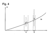
- 4 shows as a solid line 14 a typical course of the measurement curve obtained thereby and, in comparison thereto, the curve 1 from FIG. 1, which reproduces the true oscillation amplitude in the stationary regime.
- the oscillation amplitudes occurring when passing through the resonances with the angular acceleration ⁇ 1 do not allow a reliable estimation of the magnitude of a resonance. That a resonance is present, but can be concluded from the observation of their typical beats in the intervals 4, 5 of the curve 14.
- These beats are easily detected metrologically by deriving the measurement curve 14 according to the rotational speed ⁇ , forming the amount of the derivative and looking for those frequency ranges in which the derivative amount exceeds a limit.
- the time required for a single quality test is slightly greater with the method according to the second embodiment than with the first method, since in the second embodiment, those speed intervals 4, 5, at which the fast first measurement has a suspected resonance, measured a second time must be, while in the first embodiment, the entire frequency range of interest only once, but with changing acceleration values ⁇ 1 , ⁇ 2 is driven through.
- the increased measurement time has the advantage that no previous knowledge about the possible location of resonances is needed, so that preparatory measurements on specimens are superfluous.
Landscapes
- Physics & Mathematics (AREA)
- General Physics & Mathematics (AREA)
- Pathology (AREA)
- Life Sciences & Earth Sciences (AREA)
- Chemical & Material Sciences (AREA)
- Analytical Chemistry (AREA)
- Biochemistry (AREA)
- General Health & Medical Sciences (AREA)
- Health & Medical Sciences (AREA)
- Immunology (AREA)
- Acoustics & Sound (AREA)
- Engineering & Computer Science (AREA)
- Signal Processing (AREA)
- Measurement Of Mechanical Vibrations Or Ultrasonic Waves (AREA)
- Investigating Strength Of Materials By Application Of Mechanical Stress (AREA)
- Testing Of Devices, Machine Parts, Or Other Structures Thereof (AREA)
- Apparatuses For Generation Of Mechanical Vibrations (AREA)
- Crystals, And After-Treatments Of Crystals (AREA)
- General Electrical Machinery Utilizing Piezoelectricity, Electrostriction Or Magnetostriction (AREA)
- Vibration Prevention Devices (AREA)
- Arrangement Or Mounting Of Propulsion Units For Vehicles (AREA)
Description
- Die vorliegende Erfindung betrifft ein Verfahren zur Qualitätsprüfung von Aggregaten, die mit variablen Geschwindigkeiten periodisch bewegbare Teile aufweisen. Die Bewegung eines solchen Teils, sei es eine Oszillation oder eine Vibration, kann Schwingungen anderer Teile des Aggregats anregen. Wenn die Bewegungsfrequenz des anregenden Teils mit einer Resonanzfrequenz des Aggregats übereinstimmt, kann die angeregte Schwingung beträchtliche Amplituden erreichen, und es kann zur Abstrahlung von deutlich hörbaren Geräuschen kommen. Diese Geräusche sind aus zweierlei Gründen unerwünscht. Zum einen werden sie von einer Person, die sich in Hörweite des Aggregats aufhält, im Allgemeinen als lästig empfunden, zum anderen ist eine übermäßige Geräuschentwicklung eines Aggregats, die die von baugleichen Aggregaten aus der gleichen Fertigung deutlich übersteigt, häufig ein Hinweis auf einen Fehler, der zwar nicht notwendigerweise die sofortige Unbrauchbarkeit des Aggregats mit sich bringt, der aber zumindest bei einem Aggregat, das starke Geräusche erzeugt, eine geringere Lebensdauer erwarten lässt als bei einem Aggregat, das dies nicht tut. Vor dem Einbau eines solchen Aggregats in ein komplexes Gerät ist es daher zweckmäßig, eine Qualitätsprüfung des Aggregats anhand von dessen Geräuschentwicklung bei unterschiedlichen Betriebsgeschwindigkeiten durchzuführen, um ggf. Aggregate von zweifelhafter Qualität aussondern zu können.
- Um die Qualität eines Aggregats anhand seiner Geräuschentwicklung zu beurteilen, müsste man theoretisch jede Geschwindigkeit, die dessen bewegliche Teile annehmen können, einstellen und für die betreffende Geschwindigkeit resultierende Schwingungsamplituden erfassen. Die einfachste Möglichkeit, die ist zu tun, ist, die Geschwindigkeit eines beweglichen Teils innerhalb des gegebenen Bereichs der möglichen Geschwindigkeiten im Laufe der Zeit kontinuierlich zu variieren und die daraus resultierenden, im Laufe der Zeit unterschiedlichen Schwingungsamplituden zu erfassen.
- Dabei ergibt sich jedoch das Problem, dass Resonanzen des Aggregats, sofern sie auftreten, stark unterschiedliche Dämpfungen und entsprechend auch unterschiedliche spektrale Breiten aufweisen können. Eine stark gedämpfte Resonanz hat im Allgemeinen eine große spektrale Breite, so dass, wenn die Geschwindigkeit des die Resonanz anregenden beweglichen Teils kontinuierlich variiert wird, die Zeitspanne, in der dessen Geschwindigkeit geeignet ist, die Resonanz anzuregen, lang genug ist, so dass die Resonanz auch beobachtet werden kann. Je geringer die Dämpfung ist, um so geringer ist die spektrale Breite einer Resonanz, und um so kürzer ist bei einer gegebenen Änderungsrate der Frequenz des beweglichen Teils die Zeitspanne, in der die Resonanz anregbar ist.
- Wenn die Frequenz des beweglichen Teils mit der Resonanzfrequenz nicht exakt übereinstimmt, kommt es zu Schwebungen zwischen der Resonanz und der periodischen Bewegung des beweglichen Teils, das heißt die Resonanz wird durch die Bewegung des beweglichen Teils abwechselnd angeregt und gedämpft. Die Amplitude, mit der eine Resonanz tatsächlich beobachtet wird, wenn sie durch eine periodische Bewegung mit gleichmäßig zunehmender (oder abnehmender) Frequenz angeregt wird, hängt daher entscheidend von der relativen Phasenlage zwischen anregender Bewegung und Resonanz bei Übereinstimmung ihrer beiden Frequenzen ab. Diese Phasenlage ist jedoch eine zufällige Größe. Daher kann es vorkommen, dass insbesondere die Stärke von schwach gedämpften Resonanzen nicht richtig erfasst wird, weil die Zeitspanne, in der die Frequenz der Bewegung des anregenden Körpers sich mit dem Spektrum der Resonanz überschneidet, zu kurz ist, um die Resonanz wirksam anzuregen, und/oder weil beim Durchfahren durch den Resonanzbereich die Bewegung des Körpers und die Resonanzschwingung in einer ungünstigen Phasenlage zueinander stehen, die eine wirksame Anregung der Resonanzschwingung verhindert.
- Die Zuverlässigkeit, mit der die Stärke einer Resonanz erfasst werden kann, ist also um so größer, je langsamer die Bewegungsfrequenz eines beweglichen Teils variiert wird, welches die Resonanz anregen könnte. Je langsamer aber die Frequenz variiert wird, umso länger dauert ein Prüfvorgang, und um so kleiner ist die Zahl der Aggregate, die mit einer einzelnen Prüfvorrichtung in einer gegebenen Zeitspanne untersucht werden können.
- Um die Kosten der Qualitätsprüfung zu verringern, muss man daher bemüht sein, die für eine Qualitätsprüfung benötigte Zeitspanne so gering wie möglich zu halten.
- US-A-4 988 979 beschreibt ein Verfahren zur Prüfung der Qualität eines Aggregats, das wenigstens ein bewegliches Teil aufweist, das innerhalb eines gegebenen Frequenzbereiches mit unterschiedlichen Frequenzen bewegbar ist und in der Lage ist, das Aggregat zu Schwingungen anzuregen, mit den Schritten:
- a) Variieren der Frequenz des beweglichen Teils innerhalb eines Intervalls des Frequenzbereichs mit einer bestimmten Änderungsrate,
- b) Erfassen der Schwingungsamplitude des Aggregats und Bewerten des Aggregats als brauchbar oder unbrauchbar anhand der erfassten Schwingungsamplitude.
- Aufgabe der Erfindung ist, ein Verfahren zur Qualitätsprüfung zu schaffen, das eine Qualitätsprüfung in kurzer Zeit ermöglicht, und das dennoch eine sichere Erfassung und Bewertung von Resonanzen auch geringer spektraler Breite erlaubt.
- Die Aufgabe wird erfindungsgemäß dadurch gelöst, dass die Frequenz des beweglichen Teils im Laufe des Verfahrens mit zwei verschiedenen Änderungsraten variiert wird, einer ersten, die für eine "oberflächliche" Untersuchung geeignet ist und eine quantitative Beurteilung der Stärke einer Resonanz nicht ermöglichen muss, und einer zweiten Änderungsrate, die niedriger als die erste ist und so eine detaillierte Untersuchung besonders interessierender Spektralbereiche ermöglicht. Die Beurteilung der Brauchbarkeit eines Aggregats erfolgt anhand der wenigstens mit der zweiten Änderungsrate erfassten Schwingungsamplitude.
- Bei einer ersten Ausgestaltung des Verfahrens wird das mit der zweiten Änderungsrate detailliert zu untersuchende Frequenzintervall anhand der zuvor mit der ersten Änderungsrate erfassten Schwingungsamplitude festgelegt. Vorzugsweise geschieht dies, in dem zunächst der gesamte zu untersuchende Frequenzbereich mit der ersten Änderungsrate vollständig durchgefahren wird, wobei vorhandene Resonanzen sich im allgemeinen bereits in der so erfassten Schwingungsamplitude abzeichnen, auch wenn eine Beurteilung der Stärke der Resonanzen noch nicht möglich ist. Die auf diese Weise in kurzer Zeit ermittelten genauer zu untersuchenden Frequenzintervalle werden anschließend mit der zweiten, niedrigeren Änderungsrate untersucht, die eine sicherere Beurteilung der Stärke der Resonanz erlaubt.
- Einer zweiten Ausgestaltung der Erfindung zufolge genügt es, den zu untersuchenden Frequenzbereich ein einziges Mal kontinuierlich durchzufahren, wobei die Änderungsrate jeweils innerhalb eines vorher festgelegten, genau zu untersuchenden Intervalls auf dem zweiten Wert und außerhalb eines solchen Intervalls auf dem ersten Wert gehalten wird.
- Die Festlegung der mit der zweiten Änderungsrate zu untersuchenden Bereiche erfolgt in diesem Fall vorzugsweise, in dem vorab an einem mit dem zu untersuchenden Aggregat baugleichen Aggregat eine Messung der vorhandenen Resonanzfrequenzen durchgeführt wird. Da die in einer solchen Vorabmessung gefundenen Resonanzfrequenzen für eine Vielzahl von Prüfvorgängen an jeweils baugleichen Aggregaten nutzbar sind, kann diese Vorabmessung mit hohem Zeitaufwand und hoher Genauigkeit durchgeführt werden; die nachfolgenden Messungen zur Qualitätsbeurteilung der einzelnen Baugruppen benötigen demgegenüber nur kurze Zeit.
- Weitere Merkmale und Vorteile des erfindungsgemäßen Verfahrens ergeben sich aus der nachfolgenden Beschreibung von Ausführungsbeispielen mit Bezug auf die beigefügten Figuren. Es zeigen:
- Fig. 1
- die Schwingungsamplitude des Gehäuses eines Elektromotors als Funktion von dessen Drehzahl;
- Fig. 2
- die Drehbeschleunigung des Rotors im Laufe einer Messung als Funktion der Drehzahl;
- Fig. 3
- eine idealisierte Darstellung einer tatsächlich gemessenen Schwingungsamplitude als Funktion der Drehzahl in der Umgebung einer Resonanz;
- Fig. 4
- eine idealisierte Kurve der Schwingungsamplitude als Funktion der Drehzahl, die im ersten Schritt eines Verfahrens gemäß einer zweiten Ausgestaltung der Erfindung erhalten werden kann.
- Fig. 1 ist ein Graph, der die Schwingungsamplitude A eines Gehäuses eines Elektromotors, aufgetragen in willkürlichen Einheiten an der Ordinate, als Funktion der Drehzahl ω von dessen Rotor, aufgetragen an der Abszisse, zeigt. Die in Fig. 1 gezeigte Kurve 1 ist insofern idealisiert, als ihre Punkte jeweils Messpunkten entsprechen, die bei beliebig langer Messdauer bei den einzelnen Drehzahlen ω erhalten würden. In der Praxis ist eine solche Kurve nur näherungsweise realisierbar, da solche beliebig langen Messzeiten nicht zur Verfügung stehen.
- Die Kurve 1 zeigt, einem mit zunehmender Drehzahl ω anwachsenden Untergrund überlagert, zwei lokale Extrema 2, 3, die jeweils Resonanzfrequenzen des untersuchten Motors entsprechen. Wenn man mehrere Motoren einer gleichen Baureihe untersucht, stellt man im Allgemeinen fest, dass die den einzelnen Resonanzen entsprechenden Drehzahlen sich von einem Motor zum anderen nur unwesentlich unterscheiden. Die maximalen Schwingungsamplituden bei den Resonanzen, d.h. die Werte der Amplitude an den Externen 2, 3. können jedoch von Motor zu Motor stark variieren.
- Basierend auf dieser Erkenntnis wird bei einer ersten Ausgestaltung des erfindungsgemäßen Verfahrens eine Messung der Resonanzfrequenzen von Motoren einer gegebenen Bauart an einem Musterexemplar oder einer begrenzten Zahl von Musterexemplaren durchgeführt. Die Zahl der untersuchten Musterexemplare ist im Allgemeinen wesentlich kleiner als die Zahl der Motoren, an denen später eine Qualitätsprüfung durchzuführen ist, und der Zeitaufwand für das Vermessen der Musterexemplare fällt daher im Verhältnis zum Zeitaufwand für die Qualitätsprüfungen der Motoren nur wenig ins Gewicht. Die Vermessung der Musterexemplare kann daher durchgeführt werden, indem deren Drehzahl im Laufe der Zeit sehr langsam gesteigert wird und währenddessen die Amplitude der Gehäuseschwingung als Funktion der Drehzahl erfasst und aufgezeichnet wird. Bei einer solchen Messung kann das Durchfahren des Drehzahlbereichs eines solchen Motors von Null bis zu einigen Tausend Umdrehungen pro Minute eine Zeitspanne von mehreren Minuten erfordern.
- Aus den so erhaltenen Messkurven werden die Drehzahlintervalle, in Fig. 1 mit 4, 5 bezeichnet, ermittelt, in denen die Resonanzen des Gehäuses liegen.
- Bei der anschließenden Qualitätsprüfung eines einzelnen Motors wird dessen Drehgeschwindigkeit einmal von Null bis an die obere Grenze seines zulässigen Drehzahlbereichs variiert. Die dabei angewendete Änderungsrate der Drehzahl oder die Drehbeschleunigung α ist in Fig. 2 als Funktion der Drehzahl ω gezeigt. Ein erster Drehzahlbereich 6, in dem die zuvor untersuchten Musterexemplare keine Resonanz aufgewiesen haben, wird mit einer hohen Drehbeschleunigung α1 durchgefahren. Diese Drehbeschleunigung ist so gewählt, dass sie, wie später noch deutlicher werden wird, zwar das Vorhandensein einer Resonanz zu erkennen gestattet, nicht aber eine sichere Bewertung von deren Stärke erlaubt. Die Winkelbeschleunigung α1 kann z.B. in einem Bereich von 5 - 20 U/s2. liegen, so dass ein Drehzahlbereich von 0 - 200 U/s in einer Zeitspanne von 10 - 40 s durchgefahren werden kann.
- Das auf den Bereich 6 folgende Drehzahlintervall 4 wird mit einer Winkelbeschleunigung α2 durchgefahren, die maximal 1/10 bis ¼ von α1 beträgt. Diese Winkelbeschleunigung α2 ist so gewählt, dass im Laufe einer Zeitspanne, in der sich die Winkelgeschwindigkeit ω des Motors im Bereich einer Resonanz befindet, mehrere Schwebungsperioden zwischen der Drehung des Rotors und der Resonanz stattfinden können. Fig. 3 zeigt auf einer im Vergleich zu Fig. 1 gespreizten Drehzahlskala einen typischen Verlauf der Schwingungsamplitude, der beim Durchfahren des Intervalls 4 mit der niedrigen Winkelbeschleunigung α2 erfasst werden könnte. Der Verlauf der Resonanz aus Fig. 1 ist in Fig. 3 als punktierte Linie 9 dargestellt. Wenn die Drehzahl des Motors von niedrigen Drehzahlen her kommend in den Randbereich der Resonanz eintritt, so tritt zwischen der Motordrehung und der Gehäuseresonanz eine Schwebung auf. Deren Frequenz ist im Randbereich der Resonanz hoch, was sich in Fig. 3 als ein schnelles Oszillieren der Messkurve 10 bemerkbar macht. Je näher die Drehzahl der exakten Resonanzdrehzahl kommt, um so niedriger wird die Frequenz der Schwebung, und um so breiter werden die einzelnen Perioden der Messkurve 10. Wenn die Drehzahl des Motors die der Resonanzdrehzahl überschritten hat, nimmt die Schwebungsfrequenz zum Rand der Resonanz hin wieder zu. Da die Winkelbeschleunigung α klein ist, wird, während die Winkelgeschwindigkeit ω die Resonanz durchläuft, eine große Zahl von Schwebungsperioden aufgezeichnet, darunter auch welche, die so nah an der exakten Resonanzdrehzahl liegen, dass ihre Maxima wie etwa der Punkt 12 einen guten Rückschluss auf das tatsächliche Maximum der Linie 9 und damit auf die Stärke der Resonanz zulassen. Das heißt, es wird eine reproduzierbare Messung derjenigen Schwingungsamplitude erhalten, die sich einstellt, wenn der Motor dauernd mit der Resonanzfrequenz läuft. Anhand dieser Amplitude ist eine zuverlässige Beurteilung der Qualität des Motors möglich.
- Wäre die Winkelbeschleunigung α des Motors beim Durchgang durch das Intervall 4 deutlich größer, so würde sich die Zahl der beim Durchgang durch die Resonanz beobachteten Schwebungsperioden verringern, und die erhaltene Messkurve könnte z.B. die Form der strichpunktierten Kurve 13 aus Fig. 3 haben. Wie man sieht, bleiben deren Extrema deutlich unter der maximalen Amplitude der Resonanz. Wie groß die bei einem schnellen Durchlauf gemessene maximale Amplitude im Einzelfall ist, hängt von der relativen Phasenlage zwischen Motordrehung und Resonanzschwingung ab. Diese relative Phasenlage ist jedoch eine zufällige Größe, was die Amplitudenmessungen bei hoher Winkelbeschleunigung nichtreproduzierbar macht.
- Wenn die Drehfrequenz des Motors das Intervall 4 verlassen hat, wird in einem anschließenden Bereich 7, in dem anhand der an den Musterexemplaren gewonnenen Messergebnisse keine Resonanz zu erwarten ist, die Winkelbeschleunigung wieder auf den hohen Wert α1, gesetzt. In dem Intervall 5, in dem wieder eine Resonanz des Gehäuses zu erwarten ist, wird die Winkelbeschleunigung wieder auf den niedrigen zweiten Wert α2 gesetzt, um die entsprechende Resonanz genau zu vermessen. Dieser Wechsel wiederholt sich so oft, wie Resonanzfrequenzintervalle bei den Messungen an den Musterexemplaren gefunden worden sind.
- Die Breite eines Resonanzdrehzahlintervalls 4 oder 5 beträgt typischerweise ca. 100 U/min. Beim erfindungsgemäßen Verfahren wird ein solcher Bereich vorzugsweise in 5 - 7 Sek. abgefragt, was bei einer Messdauer pro Resonanz von ca. 20 µs einer Winkelbeschleunigung von ca. 2 - 4 U/s2 entspricht.
- Eine komplette Messung des Schwingungsverhaltens eines Motors kann somit innerhalb von 15 - 20 Sekunden abgeschlossen sein.
- Eine zweite Ausgestaltung des Verfahrens soll anhand von Fig. 4 veranschaulicht werden. Bei dieser Ausgestaltung wird zunächst der gesamte interessierende Drehzahlbereich des Motors mit der Drehbeschleunigung α1 durchfahren und die dabei auftretenden Schwingungsamplituden A werden aufgezeichnet. Fig. 4 zeigt als durchgezogene Linie 14 einen typischen Verlauf der dabei erhaltenen Messkurve und im Vergleich dazu die Kurve 1 aus Fig. 1, die die wahre Schwingungsamplitude im stationären Regime wiedergibt. Die beim Durchgang durch die Resonanzen mit der Winkelbeschleunigung α1 auftretenden Schwingungsamplituden erlauben keine zuverlässige Einschätzung der Stärke einer Resonanz. Dass eine Resonanz vorhanden ist, kann aber aus der Beobachtung der für sie typischen Schwebungen in den Intervallen 4, 5 der Kurve 14 geschlossen werden. Diese Schwebungen sind messtechnisch leicht zu erfassen durch Ableiten der Messkurve 14 nach der Drehzahl ω, Bilden des Betrages der Ableitung und Suchen derjenigen Frequenzbereiche, in denen der Ableitungsbetrag einen Grenzwert überschreitet.
- Wenn auf diese Weise Bereiche der Messkurve 14 wie die gezeigten Intervalle 4, 5 ermittelt worden sind, an denen sich Resonanzen befinden könnten, werden diese Intervalle anschließend mit der Winkelbeschleunigung α2 durchgefahren. Auf diese Weise wird auch hier ein Messsignal erhalten, wie als durchgezogene Kurve 10 in Fig. 3 dargestellt, und anhand der Extrema der Kurve 10 ist eine sichere Beurteilung der Stärke der Resonanz möglich.
- Der Zeitaufwand für eine einzelne Qualitätsprüfung ist mit dem Verfahren nach der zweiten Ausgestaltung geringfügig größer als mit dem ersten Verfahren, da bei der zweiten Ausgestaltung diejenigen Drehzahlintervalle 4, 5, bei denen die schnelle erste Messung einen Verdacht auf Resonanz ergeben hat, ein zweites Mal gemessen werden müssen, während bei der ersten Ausgestaltung der gesamte interessierende Frequenzbereich nur einmal, allerdings mit wechselnden Beschleunigungswerten α1, α2 durchgefahren wird. Der vergrößerten Messzeit steht jedoch als Vorteil gegenüber, dass keine vorherigen Kenntnisse über die mögliche Lage von Resonanzen benötigt werden, dass also vorbereitende Messungen an Musterexemplaren überflüssig sind.
Claims (8)
- Verfahren zur Prüfung der Qualität eines Aggregats, das wenigstens ein bewegliches Teil aufweist, das innerhalb eines gegebenen Frequenzbereichs mit unterschiedlichen Frequenzen bewegbar ist und in der Lage ist, das Aggregat zu Schwingungen anzuregen, mit den Schritten:a) Variieren der Frequenz des beweglichen Teils wenigstens innerhalb eines ersten Intervalls (6, 7) des Frequenzbereichs mit einer ersten Änderungsrate (α1),b) Variieren der Frequenz des beweglichen Teils innerhalb wenigstens eines zweiten Intervalls (4, 5) des Frequenzbereichs mit einer zweiten Änderungsrate (α2), die niedriger als die erste ist,c) Erfassen der Schwingungsamplitude (A) des Aggregats und Bewerten des Aggregats als brauchbar oder unbrauchbar anhand der erfassten Schwingungsamplitude (A).
- Verfahren nach Anspruch 1, bei dem anhand der in Schritt a) erfassten Schwingungsamplitude (A) das in Schritt b) zu untersuchende zweite Frequenzintervall (4, 5) festgelegt wird.
- Verfahren nach Anspruch 1 oder 2, bei dem in Schritt a) der gegebene Frequenzbereich mit der ersten Änderungsrate (α1) vollständig durchgefahren und anschließend in Schritt b) das zweite Intervall (4, 5) mit der zweiten Änderungsrate (α2) durchgefahren wird.
- Verfahren nach Anspruch 1, bei dem der gegebene Frequenzbereich kontinuierlich durchgefahren wird, wobei die Änderungsrate (α) innerhalb jedes zweiten Intervalls (4, 5) auf dem zweiten Wert (α2) und außerhalb davon auf dem ersten Wert (α1) gehalten wird.
- Verfahren nach Anspruch 1 oder 4, bei dem das wenigstens eine zweite Intervall (4, 5) vor Durchführung der Schritte a) und b) festgelegt wird.
- Verfahren nach Anspruch 5, dadurch gekennzeichnet, dass das wenigstens eine zweite Intervall (4, 5) durch Erfassen der Schwingungsamplitude (A) eines mit dem zu prüfenden Aggregat baugleichen Aggregats in Abhängigkeit von der Frequenz festgelegt wird.
- Verfahren nach einem der vorhergehenden Ansprüche, dadurch gekennzeichnet, dass das Aggregat eine elektrische Maschine, insbesondere ein Elektromotor, ist.
- Verfahren nach einem der vorhergehenden Ansprüche, dadurch gekennzeichnet, dass die zweite Änderungsrate (α2) weniger als ein Viertel, vorzugsweise weniger als ein Zehntel, der ersten (α1) beträgt.
Applications Claiming Priority (3)
| Application Number | Priority Date | Filing Date | Title |
|---|---|---|---|
| DE10248511 | 2002-10-17 | ||
| DE10248511A DE10248511A1 (de) | 2002-10-17 | 2002-10-17 | Qualitätsprüfungsverfahren |
| PCT/EP2003/011501 WO2004036157A2 (de) | 2002-10-17 | 2003-10-16 | Qualitätsprüfungsverfahren |
Publications (2)
| Publication Number | Publication Date |
|---|---|
| EP1563290A2 EP1563290A2 (de) | 2005-08-17 |
| EP1563290B1 true EP1563290B1 (de) | 2007-02-21 |
Family
ID=32049374
Family Applications (1)
| Application Number | Title | Priority Date | Filing Date |
|---|---|---|---|
| EP03769407A Expired - Lifetime EP1563290B1 (de) | 2002-10-17 | 2003-10-16 | Qualitätsprüfungsverfahren mittels frequenzveränderlicher anregungsschwingungen |
Country Status (7)
| Country | Link |
|---|---|
| US (1) | US7174786B2 (de) |
| EP (1) | EP1563290B1 (de) |
| AT (1) | ATE354797T1 (de) |
| AU (1) | AU2003278096A1 (de) |
| DE (2) | DE10248511A1 (de) |
| ES (1) | ES2281668T3 (de) |
| WO (1) | WO2004036157A2 (de) |
Families Citing this family (2)
| Publication number | Priority date | Publication date | Assignee | Title |
|---|---|---|---|---|
| DE102007052453B4 (de) * | 2007-11-02 | 2013-04-04 | Continental Automotive Gmbh | Diagnosevorrichtung bzw. Diagnoseverfahren bei Abgasturboladern im Betrieb am Verbrennungsmotor |
| DE102021120494B3 (de) * | 2021-08-06 | 2023-01-26 | Sandvik Mining and Construction Deutschland GmbH | Verfahren und vorrichtung zur resonanzanalyse einer schwingmaschine |
Family Cites Families (9)
| Publication number | Priority date | Publication date | Assignee | Title |
|---|---|---|---|---|
| SU966518A1 (ru) * | 1981-04-06 | 1982-10-15 | Рижский Краснознаменный Институт Инженеров Гражданской Авиации Им.Ленинского Комсомола | Способ вибрационной диагностики технического состо ни роторных машин |
| JPH02298825A (ja) * | 1989-05-13 | 1990-12-11 | Nippondenso Co Ltd | 回転機のための異常検査装置 |
| US5062296A (en) * | 1990-09-20 | 1991-11-05 | The United States Of America As Represented By The Department Of Energy | Resonant ultrasound spectroscopy |
| US5528924A (en) * | 1993-11-29 | 1996-06-25 | Leybold Inficon Inc. | Acoustic tool for analysis of a gaseous substance |
| US6098022A (en) * | 1997-10-17 | 2000-08-01 | Test Devices, Inc. | Detecting anomalies in rotating components |
| US6023975A (en) * | 1998-04-27 | 2000-02-15 | Willis; Frank A. | Method for rapid data acquisition in resonant ultrasound spectroscopy |
| US6289735B1 (en) * | 1998-09-29 | 2001-09-18 | Reliance Electric Technologies, Llc | Machine diagnostic system and method for vibration analysis |
| US6366862B1 (en) * | 2000-04-19 | 2002-04-02 | National Instruments Corporation | System and method for analyzing signals generated by rotating machines |
| GB2407639B (en) * | 2003-10-30 | 2005-12-07 | Rolls Royce Plc | A method and apparatus for analysing an oscillatable system |
-
2002
- 2002-10-17 DE DE10248511A patent/DE10248511A1/de not_active Withdrawn
-
2003
- 2003-10-16 WO PCT/EP2003/011501 patent/WO2004036157A2/de not_active Ceased
- 2003-10-16 AU AU2003278096A patent/AU2003278096A1/en not_active Abandoned
- 2003-10-16 DE DE50306600T patent/DE50306600D1/de not_active Expired - Lifetime
- 2003-10-16 EP EP03769407A patent/EP1563290B1/de not_active Expired - Lifetime
- 2003-10-16 ES ES03769407T patent/ES2281668T3/es not_active Expired - Lifetime
- 2003-10-16 AT AT03769407T patent/ATE354797T1/de not_active IP Right Cessation
-
2005
- 2005-04-18 US US11/108,542 patent/US7174786B2/en not_active Expired - Fee Related
Also Published As
| Publication number | Publication date |
|---|---|
| US20050188767A1 (en) | 2005-09-01 |
| WO2004036157A2 (de) | 2004-04-29 |
| WO2004036157A3 (de) | 2004-08-12 |
| ATE354797T1 (de) | 2007-03-15 |
| EP1563290A2 (de) | 2005-08-17 |
| AU2003278096A1 (en) | 2004-05-04 |
| AU2003278096A8 (en) | 2004-05-04 |
| DE50306600D1 (de) | 2007-04-05 |
| DE10248511A1 (de) | 2004-04-29 |
| US7174786B2 (en) | 2007-02-13 |
| ES2281668T3 (es) | 2007-10-01 |
Similar Documents
| Publication | Publication Date | Title |
|---|---|---|
| DE102008027016B4 (de) | Verfahren und Vorrichtung zur Analyse von Geräuschen eines Kraftfahrzeuges | |
| EP3830540B1 (de) | Verfahren zum erkennen einer veränderung am betriebsverhalten eines kurbeltriebs eines kraftfahrzeugs | |
| DE102011089101B4 (de) | Verfahren und Vorrichtung zum Erkennen eines Fehlers bei einem Antriebsstrang eines Fahrzeugs | |
| EP1764589B1 (de) | Verfahren zur Prüfung eines Coriolis-Massendurchflussmessgeräts | |
| DE3408492A1 (de) | Geraeuschmesseinrichtung zur messung von anormalen geraeuschen bei getrieben | |
| DE102018101057A1 (de) | Detektieren einer fehlerhaften Sammlung von Vibrationsdaten | |
| DE102015106849A1 (de) | Waschmaschine mit einem Beschleunigungssensor und Verfahren zum Betreiben einer Waschmaschine | |
| DE19902326C2 (de) | Verfahren zur Schadensfrüherkennung von rotierenden Maschinen | |
| DE102016202340A1 (de) | Messvorrichtung und Messverfahren | |
| EP3155228A1 (de) | Verfahren zum betreiben einer maschinenanlage mit einem wellenstrang | |
| EP1415132B1 (de) | Spektrale bewertung eines prüfobjekts | |
| DE10333410B4 (de) | Verfahren und Vorrichtung zur Bestimmung der Eigenfrequenzen eines Lagersystems mit einer gelagerten Welle | |
| DE19531858B4 (de) | Messverfahren für Abspannseile | |
| DE102019209495A1 (de) | Verfahren zum Überprüfen einer Schaufel eines Triebwerks und Überprüfungsvorrichtung zum Überprüfen einer Schaufel eines Triebwerks | |
| DE102020113126A1 (de) | Vorrichtung und Verfahren zum Messen der Schwingfestigkeit eines Bauteils | |
| EP1563290A2 (de) | Qualitätsprüfungsverfahren | |
| DE102017002624A1 (de) | Verfahren zur Produktionsüberwachung von mechanischen und elektromechanischen Produkten und Maschinen | |
| DE10351698A1 (de) | Meßverfahren zur Bestimmung der Geräuschemission eines Elektromotors und Meßvorrichtung | |
| DE19518409C1 (de) | Verfahren zur akustischen Fehlererkennung | |
| DE19640859A1 (de) | Verfahren und Vorrichtung zur zerstörungsfreien Feststellung des Werkstoffzustands in Bauteilen | |
| EP3410081B1 (de) | Effektivwertbestimmung einer maschinenschwingungsgrösse | |
| DE19612925C1 (de) | Verfahren zur Werkstoffprüfung von beschichteten Werkstoffen | |
| DE102009009714A1 (de) | Vorrichtung und Verfahren zur Drehmomentmessung an einer Turbinenwelle | |
| DE19701405C2 (de) | Überwachungssystem | |
| DE102021204884A1 (de) | Vorrichtung zur Messung eines indikativen Parameters der Drehgeschwindigkeit eines Bauteils |
Legal Events
| Date | Code | Title | Description |
|---|---|---|---|
| PUAI | Public reference made under article 153(3) epc to a published international application that has entered the european phase |
Free format text: ORIGINAL CODE: 0009012 |
|
| 17P | Request for examination filed |
Effective date: 20050517 |
|
| AK | Designated contracting states |
Kind code of ref document: A2 Designated state(s): AT BE BG CH CY CZ DE DK EE ES FI FR GB GR HU IE IT LI LU MC NL PT RO SE SI SK TR |
|
| AX | Request for extension of the european patent |
Extension state: AL LT LV MK |
|
| DAX | Request for extension of the european patent (deleted) | ||
| GRAP | Despatch of communication of intention to grant a patent |
Free format text: ORIGINAL CODE: EPIDOSNIGR1 |
|
| RIC1 | Information provided on ipc code assigned before grant |
Ipc: G01N 29/11 20060101ALI20060731BHEP Ipc: G01H 1/00 20060101ALI20060731BHEP Ipc: G01N 29/34 20060101AFI20060731BHEP |
|
| RTI1 | Title (correction) |
Free format text: QUALITY CONTROL METHOD BY VARYING THE FREQUENCY OF EXCITING VIBRATIONS |
|
| GRAS | Grant fee paid |
Free format text: ORIGINAL CODE: EPIDOSNIGR3 |
|
| GRAA | (expected) grant |
Free format text: ORIGINAL CODE: 0009210 |
|
| AK | Designated contracting states |
Kind code of ref document: B1 Designated state(s): AT BE BG CH CY CZ DE DK EE ES FI FR GB GR HU IE IT LI LU MC NL PT RO SE SI SK TR |
|
| PG25 | Lapsed in a contracting state [announced via postgrant information from national office to epo] |
Ref country code: NL Free format text: LAPSE BECAUSE OF FAILURE TO SUBMIT A TRANSLATION OF THE DESCRIPTION OR TO PAY THE FEE WITHIN THE PRESCRIBED TIME-LIMIT Effective date: 20070221 Ref country code: FI Free format text: LAPSE BECAUSE OF FAILURE TO SUBMIT A TRANSLATION OF THE DESCRIPTION OR TO PAY THE FEE WITHIN THE PRESCRIBED TIME-LIMIT Effective date: 20070221 Ref country code: DK Free format text: LAPSE BECAUSE OF FAILURE TO SUBMIT A TRANSLATION OF THE DESCRIPTION OR TO PAY THE FEE WITHIN THE PRESCRIBED TIME-LIMIT Effective date: 20070221 Ref country code: IE Free format text: LAPSE BECAUSE OF FAILURE TO SUBMIT A TRANSLATION OF THE DESCRIPTION OR TO PAY THE FEE WITHIN THE PRESCRIBED TIME-LIMIT Effective date: 20070221 Ref country code: SI Free format text: LAPSE BECAUSE OF FAILURE TO SUBMIT A TRANSLATION OF THE DESCRIPTION OR TO PAY THE FEE WITHIN THE PRESCRIBED TIME-LIMIT Effective date: 20070221 |
|
| REG | Reference to a national code |
Ref country code: GB Ref legal event code: FG4D Free format text: NOT ENGLISH |
|
| GBT | Gb: translation of ep patent filed (gb section 77(6)(a)/1977) |
Effective date: 20070221 |
|
| REG | Reference to a national code |
Ref country code: CH Ref legal event code: EP |
|
| REF | Corresponds to: |
Ref document number: 50306600 Country of ref document: DE Date of ref document: 20070405 Kind code of ref document: P |
|
| REG | Reference to a national code |
Ref country code: IE Ref legal event code: FG4D Free format text: LANGUAGE OF EP DOCUMENT: GERMAN |
|
| PG25 | Lapsed in a contracting state [announced via postgrant information from national office to epo] |
Ref country code: SE Free format text: LAPSE BECAUSE OF FAILURE TO SUBMIT A TRANSLATION OF THE DESCRIPTION OR TO PAY THE FEE WITHIN THE PRESCRIBED TIME-LIMIT Effective date: 20070521 |
|
| PG25 | Lapsed in a contracting state [announced via postgrant information from national office to epo] |
Ref country code: BG Free format text: LAPSE BECAUSE OF EXPIRATION OF PROTECTION Effective date: 20070522 |
|
| ET | Fr: translation filed | ||
| PG25 | Lapsed in a contracting state [announced via postgrant information from national office to epo] |
Ref country code: PT Free format text: LAPSE BECAUSE OF FAILURE TO SUBMIT A TRANSLATION OF THE DESCRIPTION OR TO PAY THE FEE WITHIN THE PRESCRIBED TIME-LIMIT Effective date: 20070723 |
|
| NLV1 | Nl: lapsed or annulled due to failure to fulfill the requirements of art. 29p and 29m of the patents act | ||
| REG | Reference to a national code |
Ref country code: IE Ref legal event code: FD4D |
|
| REG | Reference to a national code |
Ref country code: ES Ref legal event code: FG2A Ref document number: 2281668 Country of ref document: ES Kind code of ref document: T3 |
|
| PLBE | No opposition filed within time limit |
Free format text: ORIGINAL CODE: 0009261 |
|
| STAA | Information on the status of an ep patent application or granted ep patent |
Free format text: STATUS: NO OPPOSITION FILED WITHIN TIME LIMIT |
|
| PG25 | Lapsed in a contracting state [announced via postgrant information from national office to epo] |
Ref country code: CZ Free format text: LAPSE BECAUSE OF FAILURE TO SUBMIT A TRANSLATION OF THE DESCRIPTION OR TO PAY THE FEE WITHIN THE PRESCRIBED TIME-LIMIT Effective date: 20070221 Ref country code: RO Free format text: LAPSE BECAUSE OF FAILURE TO SUBMIT A TRANSLATION OF THE DESCRIPTION OR TO PAY THE FEE WITHIN THE PRESCRIBED TIME-LIMIT Effective date: 20070221 |
|
| 26N | No opposition filed |
Effective date: 20071122 |
|
| BERE | Be: lapsed |
Owner name: BSH BOSCH UND SIEMENS HAUSGERATE G.M.B.H. Effective date: 20071031 |
|
| PG25 | Lapsed in a contracting state [announced via postgrant information from national office to epo] |
Ref country code: GR Free format text: LAPSE BECAUSE OF FAILURE TO SUBMIT A TRANSLATION OF THE DESCRIPTION OR TO PAY THE FEE WITHIN THE PRESCRIBED TIME-LIMIT Effective date: 20070522 |
|
| PG25 | Lapsed in a contracting state [announced via postgrant information from national office to epo] |
Ref country code: MC Free format text: LAPSE BECAUSE OF NON-PAYMENT OF DUE FEES Effective date: 20071031 |
|
| REG | Reference to a national code |
Ref country code: CH Ref legal event code: PL |
|
| PG25 | Lapsed in a contracting state [announced via postgrant information from national office to epo] |
Ref country code: CH Free format text: LAPSE BECAUSE OF NON-PAYMENT OF DUE FEES Effective date: 20071031 Ref country code: LI Free format text: LAPSE BECAUSE OF NON-PAYMENT OF DUE FEES Effective date: 20071031 |
|
| PG25 | Lapsed in a contracting state [announced via postgrant information from national office to epo] |
Ref country code: BE Free format text: LAPSE BECAUSE OF NON-PAYMENT OF DUE FEES Effective date: 20071031 |
|
| PG25 | Lapsed in a contracting state [announced via postgrant information from national office to epo] |
Ref country code: EE Free format text: LAPSE BECAUSE OF FAILURE TO SUBMIT A TRANSLATION OF THE DESCRIPTION OR TO PAY THE FEE WITHIN THE PRESCRIBED TIME-LIMIT Effective date: 20070221 |
|
| PGFP | Annual fee paid to national office [announced via postgrant information from national office to epo] |
Ref country code: TR Payment date: 20081010 Year of fee payment: 6 |
|
| PG25 | Lapsed in a contracting state [announced via postgrant information from national office to epo] |
Ref country code: AT Free format text: LAPSE BECAUSE OF NON-PAYMENT OF DUE FEES Effective date: 20071016 |
|
| PGFP | Annual fee paid to national office [announced via postgrant information from national office to epo] |
Ref country code: ES Payment date: 20081027 Year of fee payment: 6 |
|
| PGFP | Annual fee paid to national office [announced via postgrant information from national office to epo] |
Ref country code: FR Payment date: 20081021 Year of fee payment: 6 |
|
| PGFP | Annual fee paid to national office [announced via postgrant information from national office to epo] |
Ref country code: GB Payment date: 20081024 Year of fee payment: 6 |
|
| PG25 | Lapsed in a contracting state [announced via postgrant information from national office to epo] |
Ref country code: CY Free format text: LAPSE BECAUSE OF FAILURE TO SUBMIT A TRANSLATION OF THE DESCRIPTION OR TO PAY THE FEE WITHIN THE PRESCRIBED TIME-LIMIT Effective date: 20070221 |
|
| PG25 | Lapsed in a contracting state [announced via postgrant information from national office to epo] |
Ref country code: LU Free format text: LAPSE BECAUSE OF NON-PAYMENT OF DUE FEES Effective date: 20071016 |
|
| PG25 | Lapsed in a contracting state [announced via postgrant information from national office to epo] |
Ref country code: HU Free format text: LAPSE BECAUSE OF FAILURE TO SUBMIT A TRANSLATION OF THE DESCRIPTION OR TO PAY THE FEE WITHIN THE PRESCRIBED TIME-LIMIT Effective date: 20070822 |
|
| REG | Reference to a national code |
Ref country code: FR Ref legal event code: ST Effective date: 20100630 |
|
| PG25 | Lapsed in a contracting state [announced via postgrant information from national office to epo] |
Ref country code: FR Free format text: LAPSE BECAUSE OF NON-PAYMENT OF DUE FEES Effective date: 20091102 |
|
| PG25 | Lapsed in a contracting state [announced via postgrant information from national office to epo] |
Ref country code: GB Free format text: LAPSE BECAUSE OF NON-PAYMENT OF DUE FEES Effective date: 20091016 |
|
| PGFP | Annual fee paid to national office [announced via postgrant information from national office to epo] |
Ref country code: DE Payment date: 20101031 Year of fee payment: 8 Ref country code: SK Payment date: 20101012 Year of fee payment: 8 |
|
| REG | Reference to a national code |
Ref country code: ES Ref legal event code: FD2A Effective date: 20110302 |
|
| PGFP | Annual fee paid to national office [announced via postgrant information from national office to epo] |
Ref country code: IT Payment date: 20101029 Year of fee payment: 8 |
|
| PG25 | Lapsed in a contracting state [announced via postgrant information from national office to epo] |
Ref country code: ES Free format text: LAPSE BECAUSE OF NON-PAYMENT OF DUE FEES Effective date: 20110301 |
|
| PG25 | Lapsed in a contracting state [announced via postgrant information from national office to epo] |
Ref country code: ES Free format text: LAPSE BECAUSE OF NON-PAYMENT OF DUE FEES Effective date: 20091017 |
|
| PG25 | Lapsed in a contracting state [announced via postgrant information from national office to epo] |
Ref country code: TR Free format text: LAPSE BECAUSE OF NON-PAYMENT OF DUE FEES Effective date: 20091016 |
|
| REG | Reference to a national code |
Ref country code: SK Ref legal event code: MM4A Ref document number: E 1876 Country of ref document: SK Effective date: 20121016 |
|
| PG25 | Lapsed in a contracting state [announced via postgrant information from national office to epo] |
Ref country code: DE Free format text: LAPSE BECAUSE OF NON-PAYMENT OF DUE FEES Effective date: 20130501 Ref country code: SK Free format text: LAPSE BECAUSE OF NON-PAYMENT OF DUE FEES Effective date: 20121016 |
|
| REG | Reference to a national code |
Ref country code: DE Ref legal event code: R119 Ref document number: 50306600 Country of ref document: DE Effective date: 20130501 |
|
| PG25 | Lapsed in a contracting state [announced via postgrant information from national office to epo] |
Ref country code: IT Free format text: LAPSE BECAUSE OF NON-PAYMENT OF DUE FEES Effective date: 20121016 |