EP1560992B1 - Support pour objets tels que des pare-soleil - Google Patents
Support pour objets tels que des pare-soleil Download PDFInfo
- Publication number
- EP1560992B1 EP1560992B1 EP03779532A EP03779532A EP1560992B1 EP 1560992 B1 EP1560992 B1 EP 1560992B1 EP 03779532 A EP03779532 A EP 03779532A EP 03779532 A EP03779532 A EP 03779532A EP 1560992 B1 EP1560992 B1 EP 1560992B1
- Authority
- EP
- European Patent Office
- Prior art keywords
- post according
- connecting element
- ground
- mounting
- post
- Prior art date
- Legal status (The legal status is an assumption and is not a legal conclusion. Google has not performed a legal analysis and makes no representation as to the accuracy of the status listed.)
- Expired - Lifetime
Links
- XAGFODPZIPBFFR-UHFFFAOYSA-N aluminium Chemical compound [Al] XAGFODPZIPBFFR-UHFFFAOYSA-N 0.000 claims description 2
- 229910052782 aluminium Inorganic materials 0.000 claims description 2
- 229910000831 Steel Inorganic materials 0.000 claims 1
- 239000004411 aluminium Substances 0.000 claims 1
- 230000008878 coupling Effects 0.000 claims 1
- 238000010168 coupling process Methods 0.000 claims 1
- 238000005859 coupling reaction Methods 0.000 claims 1
- 239000010959 steel Substances 0.000 claims 1
- 238000004026 adhesive bonding Methods 0.000 description 3
- 239000004568 cement Substances 0.000 description 3
- 239000000853 adhesive Substances 0.000 description 2
- 230000001070 adhesive effect Effects 0.000 description 2
- 239000003292 glue Substances 0.000 description 2
- 238000004519 manufacturing process Methods 0.000 description 2
- 208000027418 Wounds and injury Diseases 0.000 description 1
- 238000004873 anchoring Methods 0.000 description 1
- 239000010426 asphalt Substances 0.000 description 1
- 150000001875 compounds Chemical class 0.000 description 1
- 230000006378 damage Effects 0.000 description 1
- 230000001419 dependent effect Effects 0.000 description 1
- 238000006073 displacement reaction Methods 0.000 description 1
- 208000014674 injury Diseases 0.000 description 1
- 238000003780 insertion Methods 0.000 description 1
- 230000037431 insertion Effects 0.000 description 1
- 239000000463 material Substances 0.000 description 1
- 230000035515 penetration Effects 0.000 description 1
- 239000004576 sand Substances 0.000 description 1
- 229910001220 stainless steel Inorganic materials 0.000 description 1
- 239000010935 stainless steel Substances 0.000 description 1
- XLYOFNOQVPJJNP-UHFFFAOYSA-N water Substances O XLYOFNOQVPJJNP-UHFFFAOYSA-N 0.000 description 1
Images

Classifications
-
- E—FIXED CONSTRUCTIONS
- E04—BUILDING
- E04H—BUILDINGS OR LIKE STRUCTURES FOR PARTICULAR PURPOSES; SWIMMING OR SPLASH BATHS OR POOLS; MASTS; FENCING; TENTS OR CANOPIES, IN GENERAL
- E04H12/00—Towers; Masts or poles; Chimney stacks; Water-towers; Methods of erecting such structures
- E04H12/22—Sockets or holders for poles or posts
- E04H12/2253—Mounting poles or posts to the holder
- E04H12/2261—Mounting poles or posts to the holder on a flat base
-
- E—FIXED CONSTRUCTIONS
- E01—CONSTRUCTION OF ROADS, RAILWAYS, OR BRIDGES
- E01F—ADDITIONAL WORK, SUCH AS EQUIPPING ROADS OR THE CONSTRUCTION OF PLATFORMS, HELICOPTER LANDING STAGES, SIGNS, SNOW FENCES, OR THE LIKE
- E01F9/00—Arrangement of road signs or traffic signals; Arrangements for enforcing caution
- E01F9/60—Upright bodies, e.g. marker posts or bollards; Supports for road signs
- E01F9/658—Upright bodies, e.g. marker posts or bollards; Supports for road signs characterised by means for fixing
- E01F9/673—Upright bodies, e.g. marker posts or bollards; Supports for road signs characterised by means for fixing for holding sign posts or the like
- E01F9/681—Upright bodies, e.g. marker posts or bollards; Supports for road signs characterised by means for fixing for holding sign posts or the like the sign posts being fastened by removable means, e.g. screws or bolts
-
- A—HUMAN NECESSITIES
- A45—HAND OR TRAVELLING ARTICLES
- A45B—WALKING STICKS; UMBRELLAS; LADIES' OR LIKE FANS
- A45B11/00—Umbrellas characterised by their shape or attachment
- A45B2011/005—Umbrellas characterised by their shape or attachment characterised by their shape
Definitions
- the invention relates to a stand for objects such as umbrellas, signs, billboards or clothes dryers with an upper part for receiving a shaft of the article and a bottom facing the bottom, with a central connecting element, which is arranged in the region of the lower part and with a firmly anchored in the ground bracket is positively connected.
- Such stands are made of the most diverse materials, with an essential prerequisite, depending on the required stability, more or less great weight. There are therefore those that z. B. made of concrete and are difficult to transport at a greater weight. There are also those that can be filled with water or sand, these stands can be easily transported after emptying.
- a major disadvantage of all these stands, however, is that they are either left alone when not in use, causing an accident and injury risk because people trip over it or can bump into it, or always transported away and brought back to the place of use if necessary but this is difficult or difficult to do in the case of heavy stands or in the case of empty stands. It is also known to insert or install pipes in the ground into which the shank of the article can be inserted. However, these tubes must have a larger diameter than the shaft and are therefore unsightly.
- the invention is therefore an object of the invention to provide a generic stand available that can be easily assembled and dismantled with high stability and has a low weight.
- a generic stand for achieving this object is characterized in that an elastic layer is arranged on the bottom plate on the side facing the bottom.
- the stand according to the invention since it is firmly anchored to the ground, can be made relatively easy, as it is its stability not achieved by a high weight. After it has been separated from its anchored in the ground bracket, stay well No disturbing parts back, because the holder can be sunk completely into the ground.
- the central connecting element is a screw and the holder is a dowel. But it can also be used other compounds such as screw thread quick connections, bayonet-type connections or snap connections.
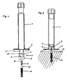
- a first embodiment of a stator according to the invention which consists essentially of an upper part 1 in the form of a tube and a lower part 2 in the form of a disc which is welded to the tube 1.
- a disc 2 instead of a disc 2 but other forms of a lower part are conceivable, for. B. star-like feet or supports that are not attached to the lower end of the tube 1, but slightly higher, and project obliquely downwards.
- a screw 3 is fixed in the interior of the tube 1, such as Fig. 2 shows.
- a holding part 4 is provided, which consists of a receiving part 5 and a fixing part 6.
- the receiving part 5 is attached to the lower end of the tube 1, for example, welded or glued.
- the screw 3 is inserted from above through the receiving part 5, wherein the screw head 8 is rotatably received in a recess 9 in the receiving part 5.
- the fixing part 6 On its upper side, the fixing part 6 furthermore has a centering opening 10.
- a shaft of a parasol, a sign, a billboard, a clothes dryer or the like can be plugged from above, wherein the shaft, provided he has a tip at its lower end in the centering opening 10 is centered.
- a known per se clamping screw sleeve with which an inserted shaft can be centered by twisting and clamped e.g. a known per se clamping screw sleeve with which an inserted shaft can be centered by twisting and clamped.
- connection with the ground is such that z.
- the stand can then be screwed with its screw 3 in the holder 11 until the plate 2 rests firmly on the floor.
- central connecting element can be different in size.
- the anchoring of the stand according to the invention with the ground can be further simplified in that instead of a conventional screw 3, 3 ', which must be screwed into a dowel 11, 11' screw thread quick connections, bayonet-type connections or snap-rotary joints are used.
- an elastic layer 15 shown on the underside of the plate 2 which may be a rubber plate, for example, which is glued to the underside of the bottom plate 2.
- the rubber plate 15 is preferably close to the screw 3, 3 'and serves to compensate for unevenness and to prevent rubbing of the underside of the bottom plate 2 on the surface 14 of the floor, such as tiles or paving stones.
- the holder 11, 11 ' e.g. a screw plug, must be firmly anchored in the bottom 14. This can e.g. by gluing or cementing in an opening in the floor. It is essential that the dowel 11, 11 'straight, i. is used at right angles to the bottom surface 14 and the underside of the bottom plate 2.
- the rubber plate 15 is helpful because the dowel 11 can be screwed onto the screw 3 so far that the dowel 11, 11 'sealingly abuts the rubber plate 15, so that an ingress of adhesive or cement paste between the dowel 11, 11 'and the screw 3 is prevented, which could make it difficult or completely prevent a solution of this connection.
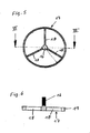
- a mounting device according to the insertion of the anchor 11, 11 'in the ground FIGS. 5 and 6 provided, which consists essentially of a carrier 16, in particular a threaded pin, protrude from the radial struts 18. At the free ends of the struts 18, a support ring 19 is attached.
- a suitable means for example glue or cement
- a stand for objects such as umbrellas, signs, billboards or clothes dryers has an upper part 1 for receiving a shaft of the article and a bottom facing the base 2, 2 'on.
- a central connecting element 3, 3 ' e.g. a screw, provided in the region of the lower part 2, 2 'arranged and with a firmly anchored in the ground holder 11, 11', z. B. a dowel, is positively connected.
Landscapes
- Engineering & Computer Science (AREA)
- Architecture (AREA)
- Civil Engineering (AREA)
- Structural Engineering (AREA)
- Holders For Apparel And Elements Relating To Apparel (AREA)
- Road Signs Or Road Markings (AREA)
- Drying Of Solid Materials (AREA)
- Building Awnings And Sunshades (AREA)
- Supports Or Holders For Household Use (AREA)
- Joining Of Building Structures In Genera (AREA)
- Floor Finish (AREA)
Abstract
Claims (19)
- Support pour des objets comme les parasols, les panneaux de signalisation, les tableaux publicitaires ou les séchoirs parapluies, avec une partie supérieure (1) destinée à réceptionner une tige de l'objet et une partie inférieure (2, 2') faisant face au sol, avec un élément de liaison (3, 3') central, qui est disposé dans la zone de la partie inférieure (2, 2') et qui peut être relié par complémentarité de forme avec une attache (11, 11') solidement ancrée dans le sol, la partie inférieure (2, 2') étant reliée de façon inamovible, par exemple soudée avec la partie supérieure (1), caractérisé en ce que sur la plaque de base (2'), sur le côté faisant face au sol est disposée une couche élastique (15).
- Support selon la revendication 1, caractérisé en ce que l'élément de liaison central (3, 3') est une vis et l'attache (11, 11') est une cheville.
- Support selon la revendication 1, caractérisé en ce que l'élément de liaison central (3, 3') et l'attache (11, 11') forment un raccord rapide à vis.
- Support selon la revendication 1, caractérisé en ce que l'élément de liaison central (3, 3') et l'attache (11, 11') peuvent être reliés l'un à l'autre par l'intermédiaire d'un raccord par cliquet et/ou d'un raccord rotatif.
- Support selon l'une quelconque des revendications 1 à 4, caractérisé en ce que l'attache (11, 11') est en acier inoxydable ou en aluminium.
- Support selon l'une quelconque des revendications 1 à 5, caractérisé en ce que la partie supérieure (1) est un tube et la partie inférieure (2) est une plaque reliée à la manière d'une bride avec le tube.
- Support selon la revendication 6, caractérisé en ce que sur son extrémité faisant face à l'attache (11), le tube (1) est ouvert et en ce que l'élément de liaison (11) est fixé sur le tube (1) par cette extrémité.
- Support selon la revendication 7, caractérisé en ce qu'une pièce de maintien (4) pour l'élément de liaison (3) est fixée dans le tube (1).
- Support selon la revendication 8, caractérisé en ce que la pièce de maintien (4) est constituée d'une pièce de logement (5) à travers laquelle s'étend l'élément de liaison (3) et d'une pièce de fixation (6) par laquelle l'élément de liaison (3) est tenu dans la pièce de logement (5).
- Support selon la revendication 9, caractérisé en ce que la pièce de logement (5) et la pièce de fixation (6) sont vissées (7) l'une à l'autre.
- Support selon la revendication 9 ou 10, caractérisé en ce que la pièce de fixation (6) est un orifice de centrage (10).
- Support selon la revendication 1 à 11, caractérisé en ce que la partie inférieure (2') est formée par une plaque de base fixement reliée sensiblement à pleine surface avec la partie supérieure (1).
- Support selon l'une quelconque des revendications 1 à 12, caractérisé en ce que l'élément de liaison est inséré dans la plaque de base (2') à travers un trou (13).
- Support selon l'une quelconque des revendications 1 à 13, caractérisé en ce que l'élément de liaison (3, 3') est relié de manière inamovible, par exemple collé sur le support.
- Support selon les revendications 12 à 14, caractérisé en ce que l'élément de liaison (13) est une vis (3') vissée dans la plaque de base (2') et fixée le cas échéant dans cette dernière.
- Support selon l'une quelconque des revendications 1 à 15, caractérisé en ce que la partie supérieure (1) comporte dans la zone de son extrémité supérieure un dispositif de serrage pour la tige de l'objet.
- Support selon l'une quelconque des revendications 1 à 16, caractérisé en ce que la couche élastique (15) est une plaque en caoutchouc ou similaire.
- Support selon l'une quelconque des revendications 1 à 17, caractérisé en ce que la couche (15) est fixement reliée, par exemple collée sur la partie inférieure (2').
- Support selon l'une quelconque des revendications 1 à 18, caractérisé en ce que la couche (15) entoure étroitement l'élément de liaison (3, 3') central.
Applications Claiming Priority (3)
| Application Number | Priority Date | Filing Date | Title |
|---|---|---|---|
| AT77402U | 2002-11-14 | ||
| AT0077402U AT6883U1 (de) | 2002-11-14 | 2002-11-14 | Ständer für gegenstände wie sonnenschirme |
| PCT/AT2003/000344 WO2004044354A2 (fr) | 2002-11-14 | 2003-11-14 | Support pour objets tels que des pare-soleil |
Publications (2)
| Publication Number | Publication Date |
|---|---|
| EP1560992A2 EP1560992A2 (fr) | 2005-08-10 |
| EP1560992B1 true EP1560992B1 (fr) | 2012-01-25 |
Family
ID=32046326
Family Applications (1)
| Application Number | Title | Priority Date | Filing Date |
|---|---|---|---|
| EP03779532A Expired - Lifetime EP1560992B1 (fr) | 2002-11-14 | 2003-11-14 | Support pour objets tels que des pare-soleil |
Country Status (8)
| Country | Link |
|---|---|
| US (1) | US20060054765A1 (fr) |
| EP (1) | EP1560992B1 (fr) |
| CN (1) | CN1711401B (fr) |
| AT (2) | AT6883U1 (fr) |
| AU (1) | AU2003287738B2 (fr) |
| CA (1) | CA2505897A1 (fr) |
| DE (2) | DE20320460U1 (fr) |
| WO (1) | WO2004044354A2 (fr) |
Cited By (1)
| Publication number | Priority date | Publication date | Assignee | Title |
|---|---|---|---|---|
| US9233054B2 (en) | 2004-11-16 | 2016-01-12 | 3M Innovative Properties Company | Dental fillers including a phosphorus-containing surface treatment, and compositions and methods thereof |
Families Citing this family (8)
| Publication number | Priority date | Publication date | Assignee | Title |
|---|---|---|---|---|
| US20110036026A1 (en) * | 2009-08-11 | 2011-02-17 | Lee Robert E | Ergonomic post with integral anchor |
| GB2504548A (en) * | 2012-08-03 | 2014-02-05 | A Fax Ltd | Compression post foot connection |
| GB2504549A (en) * | 2012-08-03 | 2014-02-05 | A Fax Ltd | Coaxial, post, foot anchor and ground anchor connections |
| JP2015206169A (ja) * | 2014-04-17 | 2015-11-19 | Nok株式会社 | 視線誘導標識柱の脚部取付け構造 |
| CN104055456A (zh) * | 2014-07-06 | 2014-09-24 | 李健 | 自对正不滑动折叠坐便椅 |
| US11319724B2 (en) * | 2019-08-01 | 2022-05-03 | Tindall Corporation | System and method for coupling a post to a foundation |
| CN112726450A (zh) * | 2020-12-31 | 2021-04-30 | 杭州半云科技有限公司 | 一种智慧城市交通道路指示装置 |
| US11993928B2 (en) * | 2021-07-12 | 2024-05-28 | Falkbuilt Ltd. | Hybrid wall system |
Family Cites Families (24)
| Publication number | Priority date | Publication date | Assignee | Title |
|---|---|---|---|---|
| US1696288A (en) * | 1926-05-17 | 1928-12-25 | Underwood Frank Karl | Tree holder |
| US2684245A (en) * | 1951-10-20 | 1954-07-20 | Jacoby Louis | Golf hole protector |
| US3289369A (en) * | 1964-08-11 | 1966-12-06 | Spring City Foundry Company | Light standard base hold down |
| GB1138339A (en) * | 1965-12-28 | 1969-01-01 | Geoffrey William Thomas | Support apparatus, particularly but not exclusively for games posts |
| DE8513417U1 (de) * | 1985-05-07 | 1989-01-12 | Wenninger, Johann, 8351 Mariaposching | Säulenfuß |
| US4850564A (en) * | 1988-09-26 | 1989-07-25 | Gilberto Padin | Windproof umbrella holder |
| US5271196A (en) * | 1991-12-13 | 1993-12-21 | Roy Fanti | Stabilizer retention device for beach umbrellas |
| SE501275C2 (sv) * | 1992-02-05 | 1995-01-09 | A Kit Ab | Förankringsdon för förankring av föremål i underlag såsom t ex mark |
| US5207175A (en) * | 1992-03-17 | 1993-05-04 | Garbis Andonian | Marker post |
| US5169111A (en) * | 1992-03-18 | 1992-12-08 | Dunaj Raymond C | Collapsible stand for shade umbrellas |
| DE9302983U1 (de) * | 1993-03-02 | 1993-07-29 | Eberhardt, Beatrice, Dr., 4100 Duisburg | Stativ zum Halten von Sonnenschirmen |
| US5354031A (en) * | 1993-03-29 | 1994-10-11 | Dayva International, Inc. | Low-profile umbrella base |
| US5369925A (en) * | 1993-06-01 | 1994-12-06 | Hardy Manufacturing, Inc. | Post protector |
| SE9302126L (sv) * | 1993-06-18 | 1994-04-11 | Dekont Teknik Ab | Vid påkörning eftergivlig stolpanordning med stolpfot |
| US5535978A (en) * | 1994-07-12 | 1996-07-16 | Rodriguez; Arturo E. | Beach umbrella anchoring apparatus |
| US5697190A (en) * | 1995-11-13 | 1997-12-16 | Scribner; Marshall N. | Earth anchored pole apparatus |
| US6202369B1 (en) * | 1996-08-21 | 2001-03-20 | Stanley E. Partee | Universal anchor system |
| US5895017A (en) * | 1997-09-11 | 1999-04-20 | Mcmillan, Jr.; Keith S. | Portable furniture base |
| US6484471B2 (en) * | 2000-03-22 | 2002-11-26 | Patent Applied Technology | Adhesive fixed anchors |
| US6393795B1 (en) * | 2000-08-16 | 2002-05-28 | Illinois Tool Works Inc. | Adhesive anchor and system |
| US6471176B2 (en) * | 2001-02-20 | 2002-10-29 | Edmond R. Berthiaume | Staff holder |
| US6402117B1 (en) * | 2001-07-03 | 2002-06-11 | Jui-Yi Tsai | Display frame fixing device |
| US6953180B1 (en) * | 2001-07-06 | 2005-10-11 | Jose Luis Ruvalcaba | Anchoring device for an umbrella |
| US6908067B2 (en) * | 2002-10-07 | 2005-06-21 | Reinhard Herman Clasen | Ground anchoring sunshade umbrella stand |
-
2002
- 2002-11-14 AT AT0077402U patent/AT6883U1/de not_active IP Right Cessation
-
2003
- 2003-11-14 AT AT03779532T patent/ATE542970T1/de active
- 2003-11-14 AU AU2003287738A patent/AU2003287738B2/en not_active Ceased
- 2003-11-14 DE DE20320460U patent/DE20320460U1/de not_active Expired - Lifetime
- 2003-11-14 CN CN2003801032264A patent/CN1711401B/zh not_active Expired - Fee Related
- 2003-11-14 DE DE20321485U patent/DE20321485U1/de not_active Expired - Lifetime
- 2003-11-14 US US10/535,150 patent/US20060054765A1/en not_active Abandoned
- 2003-11-14 CA CA002505897A patent/CA2505897A1/fr not_active Abandoned
- 2003-11-14 EP EP03779532A patent/EP1560992B1/fr not_active Expired - Lifetime
- 2003-11-14 WO PCT/AT2003/000344 patent/WO2004044354A2/fr not_active Ceased
Cited By (1)
| Publication number | Priority date | Publication date | Assignee | Title |
|---|---|---|---|---|
| US9233054B2 (en) | 2004-11-16 | 2016-01-12 | 3M Innovative Properties Company | Dental fillers including a phosphorus-containing surface treatment, and compositions and methods thereof |
Also Published As
| Publication number | Publication date |
|---|---|
| WO2004044354A3 (fr) | 2005-01-06 |
| DE20320460U1 (de) | 2004-11-18 |
| DE20321485U1 (de) | 2007-08-16 |
| US20060054765A1 (en) | 2006-03-16 |
| ATE542970T1 (de) | 2012-02-15 |
| AU2003287738A1 (en) | 2004-06-03 |
| CA2505897A1 (fr) | 2004-05-27 |
| CN1711401A (zh) | 2005-12-21 |
| CN1711401B (zh) | 2010-10-06 |
| AU2003287738B2 (en) | 2009-10-29 |
| WO2004044354A2 (fr) | 2004-05-27 |
| EP1560992A2 (fr) | 2005-08-10 |
| AT6883U1 (de) | 2004-05-25 |
Similar Documents
| Publication | Publication Date | Title |
|---|---|---|
| EP1560992B1 (fr) | Support pour objets tels que des pare-soleil | |
| EP2003270B1 (fr) | Système et procédé de fixation d'un objet en forme de mât ou de poteau dans le sol en terre avec une partie réceptrice en plusieurs pièces pouvant être vissées sur le sol en terre | |
| CH641862A5 (de) | Bodenhuelse fuer eine darin einsteckbare und zu haltende stange. | |
| DE1893892U (de) | In den erdboden einschraubbarer erdanker. | |
| DE3721115A1 (de) | Traeger von strassenverkehrszeichen, richtungsweisern, fussgaengerschutzzaeunen und aehnlichem | |
| EP2497879B1 (fr) | Fixation d'une plaque de monument sur une fondation | |
| DE202010016548U1 (de) | Vorrichtung zur kippsicheren Aufnahme einer Stange | |
| DE10347536B4 (de) | Verankerung eines Säulenschwenkkranes | |
| DE202006015706U1 (de) | Befestigungseinrichtung für einen Mast aus einem Faser-Kunststoff-Verbundmaterial | |
| DE102010009140B4 (de) | System zur Bodenverankerung von Aufbauten | |
| EP1719859B1 (fr) | Ancre de sol | |
| DE102008037938B4 (de) | Fundamentsystem zum Ausrichten und Befestigen eines stabförmigen Gegenstandes im Erdboden | |
| DE10240586A1 (de) | Vorrichtung zur Befestigung von stabförmigen Gegenständen z.B. Rohrpfosten im Naturboden und in befestigtem Untergrund | |
| DE10142399A1 (de) | Befestigungeinrichtung für eine rohrförmige Stange und Verwendung der Befestigungseinrichtung zum Aufstellen von Fahnenmasten | |
| DE9406750U1 (de) | Fuß für Gartenschirme, Sonnenschirme, mobile Begrenzungs-, Sichtschutzeinrichtungen und dergleichen | |
| DE7931559U1 (de) | Halterung für Stangen, wie Schilder-, Hinweis- o.ä. Stangen | |
| DE102008005952B4 (de) | Vorrichtung zur lösbaren Befestigung | |
| DE102016106330A1 (de) | Verfahren, Vorrichtung und Bodendübelsystem zur Pfostenbefestigung | |
| DE29713525U1 (de) | Vorrichtung zum Aufstellen eines Mastes | |
| DE29507183U1 (de) | Zusammenlegbarer Schirmständer | |
| DE29512048U1 (de) | Pfahlverkleidung | |
| DE202006015172U1 (de) | Multifunktionale Bodenhülse | |
| DE202005015564U1 (de) | Ständer für längliche stangenartige Endbereiche aufweisende Gegenstände | |
| DE202008001062U1 (de) | Vorrichtung zur lösbaren Befestigung | |
| DE7031616U (de) | Vorrichtung zur verankerung von masten. |
Legal Events
| Date | Code | Title | Description |
|---|---|---|---|
| PUAI | Public reference made under article 153(3) epc to a published international application that has entered the european phase |
Free format text: ORIGINAL CODE: 0009012 |
|
| 17P | Request for examination filed |
Effective date: 20050423 |
|
| AK | Designated contracting states |
Kind code of ref document: A2 Designated state(s): AT BE BG CH CY CZ DE DK EE ES FI FR GB GR HU IE IT LI LU MC NL PT RO SE SI SK TR |
|
| AX | Request for extension of the european patent |
Extension state: AL LT LV MK |
|
| GRAP | Despatch of communication of intention to grant a patent |
Free format text: ORIGINAL CODE: EPIDOSNIGR1 |
|
| GRAS | Grant fee paid |
Free format text: ORIGINAL CODE: EPIDOSNIGR3 |
|
| GRAA | (expected) grant |
Free format text: ORIGINAL CODE: 0009210 |
|
| AK | Designated contracting states |
Kind code of ref document: B1 Designated state(s): AT BE BG CH CY CZ DE DK EE ES FI FR GB GR HU IE IT LI LU MC NL PT RO SE SI SK TR |
|
| AX | Request for extension of the european patent |
Extension state: AL LT LV MK |
|
| REG | Reference to a national code |
Ref country code: GB Ref legal event code: FG4D Free format text: NOT ENGLISH |
|
| REG | Reference to a national code |
Ref country code: CH Ref legal event code: EP |
|
| REG | Reference to a national code |
Ref country code: AT Ref legal event code: REF Ref document number: 542970 Country of ref document: AT Kind code of ref document: T Effective date: 20120215 |
|
| REG | Reference to a national code |
Ref country code: IE Ref legal event code: FG4D |
|
| REG | Reference to a national code |
Ref country code: DE Ref legal event code: R096 Ref document number: 50314191 Country of ref document: DE Effective date: 20120322 |
|
| REG | Reference to a national code |
Ref country code: NL Ref legal event code: VDEP Effective date: 20120125 |
|
| LTLA | Lt: lapse of european patent or patent extension | ||
| PG25 | Lapsed in a contracting state [announced via postgrant information from national office to epo] |
Ref country code: BG Free format text: LAPSE BECAUSE OF FAILURE TO SUBMIT A TRANSLATION OF THE DESCRIPTION OR TO PAY THE FEE WITHIN THE PRESCRIBED TIME-LIMIT Effective date: 20120425 Ref country code: NL Free format text: LAPSE BECAUSE OF FAILURE TO SUBMIT A TRANSLATION OF THE DESCRIPTION OR TO PAY THE FEE WITHIN THE PRESCRIBED TIME-LIMIT Effective date: 20120125 |
|
| REG | Reference to a national code |
Ref country code: IE Ref legal event code: FD4D |
|
| PG25 | Lapsed in a contracting state [announced via postgrant information from national office to epo] |
Ref country code: FI Free format text: LAPSE BECAUSE OF FAILURE TO SUBMIT A TRANSLATION OF THE DESCRIPTION OR TO PAY THE FEE WITHIN THE PRESCRIBED TIME-LIMIT Effective date: 20120125 Ref country code: GR Free format text: LAPSE BECAUSE OF FAILURE TO SUBMIT A TRANSLATION OF THE DESCRIPTION OR TO PAY THE FEE WITHIN THE PRESCRIBED TIME-LIMIT Effective date: 20120426 Ref country code: PT Free format text: LAPSE BECAUSE OF FAILURE TO SUBMIT A TRANSLATION OF THE DESCRIPTION OR TO PAY THE FEE WITHIN THE PRESCRIBED TIME-LIMIT Effective date: 20120525 |
|
| PG25 | Lapsed in a contracting state [announced via postgrant information from national office to epo] |
Ref country code: CY Free format text: LAPSE BECAUSE OF FAILURE TO SUBMIT A TRANSLATION OF THE DESCRIPTION OR TO PAY THE FEE WITHIN THE PRESCRIBED TIME-LIMIT Effective date: 20120125 |
|
| PG25 | Lapsed in a contracting state [announced via postgrant information from national office to epo] |
Ref country code: DK Free format text: LAPSE BECAUSE OF FAILURE TO SUBMIT A TRANSLATION OF THE DESCRIPTION OR TO PAY THE FEE WITHIN THE PRESCRIBED TIME-LIMIT Effective date: 20120125 Ref country code: IE Free format text: LAPSE BECAUSE OF FAILURE TO SUBMIT A TRANSLATION OF THE DESCRIPTION OR TO PAY THE FEE WITHIN THE PRESCRIBED TIME-LIMIT Effective date: 20120125 Ref country code: RO Free format text: LAPSE BECAUSE OF FAILURE TO SUBMIT A TRANSLATION OF THE DESCRIPTION OR TO PAY THE FEE WITHIN THE PRESCRIBED TIME-LIMIT Effective date: 20120125 Ref country code: SI Free format text: LAPSE BECAUSE OF FAILURE TO SUBMIT A TRANSLATION OF THE DESCRIPTION OR TO PAY THE FEE WITHIN THE PRESCRIBED TIME-LIMIT Effective date: 20120125 Ref country code: EE Free format text: LAPSE BECAUSE OF FAILURE TO SUBMIT A TRANSLATION OF THE DESCRIPTION OR TO PAY THE FEE WITHIN THE PRESCRIBED TIME-LIMIT Effective date: 20120125 Ref country code: CZ Free format text: LAPSE BECAUSE OF FAILURE TO SUBMIT A TRANSLATION OF THE DESCRIPTION OR TO PAY THE FEE WITHIN THE PRESCRIBED TIME-LIMIT Effective date: 20120125 Ref country code: SE Free format text: LAPSE BECAUSE OF FAILURE TO SUBMIT A TRANSLATION OF THE DESCRIPTION OR TO PAY THE FEE WITHIN THE PRESCRIBED TIME-LIMIT Effective date: 20120125 |
|
| PG25 | Lapsed in a contracting state [announced via postgrant information from national office to epo] |
Ref country code: IT Free format text: LAPSE BECAUSE OF FAILURE TO SUBMIT A TRANSLATION OF THE DESCRIPTION OR TO PAY THE FEE WITHIN THE PRESCRIBED TIME-LIMIT Effective date: 20120125 Ref country code: SK Free format text: LAPSE BECAUSE OF FAILURE TO SUBMIT A TRANSLATION OF THE DESCRIPTION OR TO PAY THE FEE WITHIN THE PRESCRIBED TIME-LIMIT Effective date: 20120125 |
|
| PLBE | No opposition filed within time limit |
Free format text: ORIGINAL CODE: 0009261 |
|
| STAA | Information on the status of an ep patent application or granted ep patent |
Free format text: STATUS: NO OPPOSITION FILED WITHIN TIME LIMIT |
|
| 26N | No opposition filed |
Effective date: 20121026 |
|
| REG | Reference to a national code |
Ref country code: DE Ref legal event code: R097 Ref document number: 50314191 Country of ref document: DE Effective date: 20121026 |
|
| PG25 | Lapsed in a contracting state [announced via postgrant information from national office to epo] |
Ref country code: ES Free format text: LAPSE BECAUSE OF FAILURE TO SUBMIT A TRANSLATION OF THE DESCRIPTION OR TO PAY THE FEE WITHIN THE PRESCRIBED TIME-LIMIT Effective date: 20120506 |
|
| BERE | Be: lapsed |
Owner name: GRIENGL, HUBERT RUDOLF Effective date: 20121130 |
|
| REG | Reference to a national code |
Ref country code: CH Ref legal event code: PL |
|
| GBPC | Gb: european patent ceased through non-payment of renewal fee |
Effective date: 20121114 |
|
| PG25 | Lapsed in a contracting state [announced via postgrant information from national office to epo] |
Ref country code: LI Free format text: LAPSE BECAUSE OF NON-PAYMENT OF DUE FEES Effective date: 20121130 Ref country code: CH Free format text: LAPSE BECAUSE OF NON-PAYMENT OF DUE FEES Effective date: 20121130 |
|
| REG | Reference to a national code |
Ref country code: FR Ref legal event code: ST Effective date: 20130731 |
|
| PG25 | Lapsed in a contracting state [announced via postgrant information from national office to epo] |
Ref country code: BE Free format text: LAPSE BECAUSE OF NON-PAYMENT OF DUE FEES Effective date: 20121130 |
|
| PG25 | Lapsed in a contracting state [announced via postgrant information from national office to epo] |
Ref country code: FR Free format text: LAPSE BECAUSE OF NON-PAYMENT OF DUE FEES Effective date: 20121130 Ref country code: GB Free format text: LAPSE BECAUSE OF NON-PAYMENT OF DUE FEES Effective date: 20121114 |
|
| PGFP | Annual fee paid to national office [announced via postgrant information from national office to epo] |
Ref country code: AT Payment date: 20131126 Year of fee payment: 11 |
|
| PG25 | Lapsed in a contracting state [announced via postgrant information from national office to epo] |
Ref country code: MC Free format text: LAPSE BECAUSE OF NON-PAYMENT OF DUE FEES Effective date: 20121130 Ref country code: TR Free format text: LAPSE BECAUSE OF FAILURE TO SUBMIT A TRANSLATION OF THE DESCRIPTION OR TO PAY THE FEE WITHIN THE PRESCRIBED TIME-LIMIT Effective date: 20120125 |
|
| PG25 | Lapsed in a contracting state [announced via postgrant information from national office to epo] |
Ref country code: LU Free format text: LAPSE BECAUSE OF NON-PAYMENT OF DUE FEES Effective date: 20121114 |
|
| PG25 | Lapsed in a contracting state [announced via postgrant information from national office to epo] |
Ref country code: HU Free format text: LAPSE BECAUSE OF FAILURE TO SUBMIT A TRANSLATION OF THE DESCRIPTION OR TO PAY THE FEE WITHIN THE PRESCRIBED TIME-LIMIT Effective date: 20031114 |
|
| REG | Reference to a national code |
Ref country code: AT Ref legal event code: MM01 Ref document number: 542970 Country of ref document: AT Kind code of ref document: T Effective date: 20141114 |
|
| PG25 | Lapsed in a contracting state [announced via postgrant information from national office to epo] |
Ref country code: AT Free format text: LAPSE BECAUSE OF NON-PAYMENT OF DUE FEES Effective date: 20141114 |
|
| PGFP | Annual fee paid to national office [announced via postgrant information from national office to epo] |
Ref country code: DE Payment date: 20180427 Year of fee payment: 15 |
|
| REG | Reference to a national code |
Ref country code: DE Ref legal event code: R119 Ref document number: 50314191 Country of ref document: DE |
|
| PG25 | Lapsed in a contracting state [announced via postgrant information from national office to epo] |
Ref country code: DE Free format text: LAPSE BECAUSE OF NON-PAYMENT OF DUE FEES Effective date: 20190601 |