EP1560960B1 - Procede et dispositif pour produire une meche - Google Patents
Procede et dispositif pour produire une meche Download PDFInfo
- Publication number
- EP1560960B1 EP1560960B1 EP03772296A EP03772296A EP1560960B1 EP 1560960 B1 EP1560960 B1 EP 1560960B1 EP 03772296 A EP03772296 A EP 03772296A EP 03772296 A EP03772296 A EP 03772296A EP 1560960 B1 EP1560960 B1 EP 1560960B1
- Authority
- EP
- European Patent Office
- Prior art keywords
- twisting
- fibre composite
- pair
- drafting unit
- roving
- Prior art date
- Legal status (The legal status is an assumption and is not a legal conclusion. Google has not performed a legal analysis and makes no representation as to the accuracy of the status listed.)
- Expired - Lifetime
Links
- 238000000034 method Methods 0.000 title claims description 37
- 238000004519 manufacturing process Methods 0.000 title claims description 22
- 239000000835 fiber Substances 0.000 claims description 136
- 239000002131 composite material Substances 0.000 claims description 34
- 230000008569 process Effects 0.000 claims description 24
- 238000007378 ring spinning Methods 0.000 claims description 21
- 238000004804 winding Methods 0.000 claims description 19
- 230000000694 effects Effects 0.000 claims description 10
- 238000003780 insertion Methods 0.000 claims description 5
- 230000037431 insertion Effects 0.000 claims description 5
- 230000006978 adaptation Effects 0.000 claims description 3
- 230000001105 regulatory effect Effects 0.000 claims 1
- 238000009987 spinning Methods 0.000 description 7
- 230000015572 biosynthetic process Effects 0.000 description 5
- 238000009826 distribution Methods 0.000 description 5
- 230000008859 change Effects 0.000 description 3
- 230000009471 action Effects 0.000 description 2
- 230000002411 adverse Effects 0.000 description 2
- 238000013461 design Methods 0.000 description 2
- 238000003892 spreading Methods 0.000 description 2
- 230000007480 spreading Effects 0.000 description 2
- 230000007704 transition Effects 0.000 description 2
- 241000239290 Araneae Species 0.000 description 1
- 229920000742 Cotton Polymers 0.000 description 1
- 238000013459 approach Methods 0.000 description 1
- 230000008878 coupling Effects 0.000 description 1
- 238000010168 coupling process Methods 0.000 description 1
- 238000005859 coupling reaction Methods 0.000 description 1
- 238000010036 direct spinning Methods 0.000 description 1
- 238000004090 dissolution Methods 0.000 description 1
- 230000002349 favourable effect Effects 0.000 description 1
- 239000002657 fibrous material Substances 0.000 description 1
- 230000007257 malfunction Effects 0.000 description 1
- 239000000203 mixture Substances 0.000 description 1
- 238000007383 open-end spinning Methods 0.000 description 1
- 210000000056 organ Anatomy 0.000 description 1
- 230000002093 peripheral effect Effects 0.000 description 1
- 238000002360 preparation method Methods 0.000 description 1
- 238000012545 processing Methods 0.000 description 1
- 239000007787 solid Substances 0.000 description 1
- 238000007711 solidification Methods 0.000 description 1
- 230000008023 solidification Effects 0.000 description 1
- 238000006467 substitution reaction Methods 0.000 description 1
- 239000012209 synthetic fiber Substances 0.000 description 1
- 229920002994 synthetic fiber Polymers 0.000 description 1
- 238000012546 transfer Methods 0.000 description 1
Images


Classifications
-
- D—TEXTILES; PAPER
- D01—NATURAL OR MAN-MADE THREADS OR FIBRES; SPINNING
- D01H—SPINNING OR TWISTING
- D01H1/00—Spinning or twisting machines in which the product is wound-up continuously
- D01H1/11—Spinning by false-twisting
- D01H1/115—Spinning by false-twisting using pneumatic means
-
- D—TEXTILES; PAPER
- D01—NATURAL OR MAN-MADE THREADS OR FIBRES; SPINNING
- D01H—SPINNING OR TWISTING
- D01H5/00—Drafting machines or arrangements ; Threading of roving into drafting machine
- D01H5/18—Drafting machines or arrangements without fallers or like pinned bars
- D01H5/70—Constructional features of drafting elements
- D01H5/72—Fibre-condensing guides
Definitions
- the invention relates to a method for producing a Vorgarnlunte, which is suitable as a template for spinning to a fiber yarn, for example on a ring spinning machine, wherein a conveyor belt warped in a drafting and then this fiber strand receives a twisting before he wound up as a roving on a supply spool as well as a device with which this procedure can be carried out.
- flyer To produce the Flyerlunte is used as roving the so-called flyer.
- This roving machine is equipped with a drafting system and a spindle for winding up the Flyerlunte a cylindrical coil by means of a wing to support the fuse with respect to the centrifugal force caused by the spindle speeds.
- This flyer is an especially complicated and expensive machine in the spinning process.
- the usual performance of a flyer is 20-25 meters per minute.
- this low production can not be increased in view of the updraft system with flyer wings, since a higher speed is limited by the centrifugal force that endure the wings.
- the object of the present invention is to provide a method and a device in which the abovementioned disadvantages of the conventional roving process are avoided and yet to provide a template for the ring spinning machine with respect to the conveyor belt refined fiber structure that meets the characteristics of the conventional Flyerlunte.
- the fiber composite exits the drafting system in such a width relative to the width of the passageway that it is in the area between the nip line of the drafting system and the insert opening of the passage channel of the first swirl chamber leads to a splitting off of edge fibers which, due to the opposing twisting in the two swirl chambers, wrap around the fiber structure. In this way, only a small hardening of the fiber structure is achieved, which is sufficient for winding and transport, but can be easily redissolved in the delay on the ring spinning machine.
- the width of the emerging from the drafting fiber structure is tuned to about twice to 5 times the diameter of the passage channel of the first swirl chamber. It has also proved to be advantageous if the distance between the nip line of the pair of delivery rollers and the inlet opening of the passage channel of the first swirl chamber is not greater than the average fiber length.
- the average fiber length is understood to mean the length of 50% of the fibers.
- the first swirl chamber exerts a lower torque on the fiber structure than the second swirl chamber, so that the fiber structure receives a rotation excess through the second swirl chamber into the area between the drafting system exit roller pair and the first swirl chamber and can split off edge fibers with an open fiber end.
- the pressure in the first swirl chamber is kept constant and changed in adaptation to the delivery speed of the pressure in the second swirl chamber. At a higher delivery speed the pressure in the second swirl chamber is increased according to the higher delivery speed.
- the wrap is favored by a negative delay, which is subjected to the fiber chambers passing through the twist chambers. It has proved advantageous both for the winding, as well as for the further spinning of the fuse to exert on the finished fuse before winding a tension distortion to stretch the Umwindemaschinen.
- a highly productive device is created in a simple manner, in which the splitting of edge fibers for the winding of the twisted core of the fiber structure takes place without ballooning.
- high production speeds can be achieved with a smooth run.
- a device for determining the outlet width of the fiber structure the most favorable for the spread of edge fibers outlet width of the fiber structure can be matched and the uniformity of the Vorgarnlunte produced can be improved. It is essential that a certain distance is maintained between the nip of the pair of output rollers and the entrance to the first swirl chamber.
- the design of the swirl chambers with holes opening tangentially into the through-passage for the fiber structure produces a good swirl effect, without the use of rotating parts.
- the holes in the first swirl chamber have an inclination angle relative to the axis of the passage channel, a suction effect is generated in the direction of the input side of the passage channel, which ensures a good transfer of fiber structure from the drafting in the swirl chamber.
- the same can also be advantageous for the second swirl chamber.
- the speed of the delivery roller pair is adjustable. It has proved to be extremely advantageous to arrange another pair of rollers for the pair of delivery rollers so as to exert a tensioning delay on the finished roving for stretching the binding fibers.
- the winding device expediently generates parallel windings on a spool, which is suitable as a template for a ring spinning machine.
- a fiber roving for example, a conveyor belt to forgive in a drafting and then give the distorted fiber structure a twist, the twisting in a first pneumatic Swirl chamber takes place by air jets acting in the sense of a twisting opposite to the swirling in the subsequent second pneumatic swirl chamber on the fiber structure, so that a yarn is formed. Since for the production of a yarn, the fiber structure must be solidified in such a way that the highest possible breaking strength is generated in the yarn, this process is useless for the production of a roving, which is to be suitable as a template for spinning to a fiber yarn. This prior art is therefore not obvious and can not give any incentive to use the pneumatic twisting for fiber yarn with high tensile strength for producing a delayable roving.
- Example is that in the yarn production a very fine, small diameter fiber structure swirl must be given. The air flow has few attack possibilities to exert a torque on this fiber structure.
- the fiber strand is deflected into a vibrating balloon, on which the airflow can engage, such as on a crank arm, to spin the yarn.
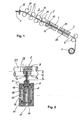
- a roving machine is used with a drafting 3
- the pair of drafting rollers 34 and 35 for the collection and first Vorverzug the original volume S and pairs of rollers 36 and 31 for the main delay has.
- a template tape is usually a conveyor belt S, which is fed with a Lunten Entry 32 the feed roller pair 34.
- Luntenver participatr in the drafting field in front of the main drafting zone is omitted, since it is important in this process that the fuse spreads enough during the delay to a sufficient width B at the exit from the exit roller pair 31 to exhibit, which is required for the distribution of the exiting fiber structure F in edge fibers FR and a turned core FD.
- the fiber structure F is passed through a pneumatic swirl device, which consists of a first swirl chamber 1 and a second swirl chamber 2. From this pneumatic twisting device, the solidified but distortable fiber structure F is withdrawn by the delivery roller pair 4 and fed to a winding device 5.
- Both swirl chambers 1 and 2 each have a passageway 11 and 21, through which the fiber structure F is passed.
- the passageways 11 and 21 are arranged so that they are aligned.
- the diameter D of these passageways 11 and 21 is preferably about 1.5 to 4 times the diameter d of the fiber strand F. in this range, all conventional rovings can be made with a single passage channel size.
- the diameter D of the passage channel 11 or 21 is kept constant over the entire length of the channel.
- the passage 11 opens at the first swirl chamber 1 holes 12 at an inclination angle ⁇ of preferably 45 °.
- the angle may be in a range of 30 to 60 degrees depending on the tuning of the swirl and the injector action. Due to the tangential junction of the channels 12, a torque is exerted on the fiber structure F by the air flow. At the same time, a suction effect is produced by the angle of inclination ⁇ , whereby the fibers emerging from the drafting system 3 are sucked into the through-channel 11.
- the bores 22 are preferably rectangular, i.
- the angle ⁇ of the bores 22 may be in a range of 45 to 90 °.
- an angle of inclination ⁇ of 90 ° achieves the best efficiency of the air flow for the swirling, there is a risk that the injected air escapes from the channel 21 counter to the direction of advance. By a slight inclination of the holes 22, this can be prevented and at the same time a suction effect can be generated.
- 12 and 22 not only a distribution over the circumference of the passage channel 11 and 21 is made at a higher number of opening holes, but also over the length.
- the fiber roving F emerging from the drafting unit 3 is a relatively coarse fiber composite compared to the yarn preparation, the lever arm given by the diameter d is large, so that the air flow can exert a large torque on the circumference of the fiber structure F. Ballooning to have a crank arm as a point of attack for the air flow for the twist distribution, has proven to be disadvantageous. The balloon formation is avoided by a close guidance of the fiber structure F in the passageway 11 or 21.
- the torque difference between the first and second swirl chamber is therefore tuned so that only the core FD of the fiber structure F until the nip 33 receives rotation, while the split-edge fibers FR are wound by the counter torque in the first swirl chamber 1 to this rotated core.
- the roving thus obtains its cohesion only by these edge fibers FR.
- edge fibers FR are therefore integrated only on one side and therefore have a free open end. This free end is detected in the first swirl chamber 1 by the swirl flow and wound against the direction of rotation of the second swirl chamber 2.
- these edge fibers FR are tightened and give the fiber structure F the required hold, which however is only so great that the delaying ability is maintained.
- the distance A is of crucial importance, wherein the size of the distance A is measured according to the fiber length in the fiber structure. Particularly good results could be obtained if this distance A is not greater than the average fiber length, that is the length which has 50% of the fibers. If this condition is exceeded for the distance A, then worse values result for the Vorgam. If the distance A is too large, there will be a breakage of the fiber structure F and thus a collapse of the entire process. A smaller distance A does not adversely affect, however, are set by the nip of the output roller pair 31 the distance A limits. It is important that in this area a clear spider triangle is formed and a splitting of edge fibers FR takes place, which serve to wrap around and thereby solidification of the fiber structure.
- outlet width B of the fiber structure an optimum value between twice to 5 times compared to the diameter D of the passage channel 11 has resulted. If this width B is not reached by the usual delay operation, but without Luntenverêtr, so is a corresponding device for determination the outlet width B of the fiber structure F in the drafting 3 provide.
- This can also be a spreading device in order to achieve the width B of the fiber structure F required for the fiber spreading when emerging from the pair of delivery rollers 31.
- it may also be a limiting device in order to achieve a required for the necessary splitting of edge fibers FR width B with simultaneous edge fiber control.
- This device is in the drafting 3 against the feed direction in front of the pair of output rollers 31, preferably to be arranged in front of the main drafting field.
- the first swirl chamber consists of a cylindrical outer part 1, in which an inner cylinder 14 is inserted against a stop 16.
- the outer cylinder 1 has at its inner periphery a recess 15 which serves as an air duct for the entering through the opening 13 compressed air.
- This inner cylinder 14 carries the nozzles 12 which are connected to the annular channel formed by the recess 15.
- different inner cylinder 14 can be used, which differ in the number and location of the nozzles 12 or in the diameter of the passage channel 11.
- a seal is made by two O-ring seals 17 in a simple manner.
- the nozzles 12 are inserted or screwed into the inner cylinder 14. After insertion of this inner cylinder 14 in the outer cylinder 1, the nozzle 12 is fixed in position, as well by the stop 16 against which the inner cylinder 14 is pushed. This ensures both a positioning of the nozzle 12, as well as the mouth of the passage channel 12 relative to the pair of output rollers 31 of the drafting system 3.
- the swirl chamber also consists of a cylindrical outer part with a recess 25 on the inner circumference and an inserted into this outer cylinder 2, continuously cylindrical inner cylinder 24 into which the nozzle bores 22 are inserted. Again, different inner cylinder 24 can be inserted without a change in the swirl chamber 2 itself.
- the nozzle bores 22 are connected independently of their number to the compressed air supply 23 via the annular channel formed by the recess 25.
- a seal is also made here by O-ring seals 27.
- This design the swirl chambers is not only simple in terms of their precise manufacture. It can also be used according to the technological requirements, various inserts with different diameters of the passage channel 11 and 21 and nozzle bores 12 and 22 respectively.
- the second swirl chamber 2 is followed by a delivery roller pair 4, which supplies the finished roving a Aufwindevor substances 5.
- a delivery roller pair 4 which supplies the finished roving a Aufwindevor substances 5.
- this pair of delivery rollers 4 may be provided a Lunten Entry, which is suitably tubular.
- balloon formation should be avoided as far as possible, since these adversely affect the generated vorgam, e.g. lead to uncontrolled Fehlvermann or centrifuging of peripheral fibers FR and thus flight formation. Therefore, the free lengths between the swirl chambers 1 and 2 and also the Lunten Adjust are to be kept as small as possible. However, these distances are required for the removal of the air emerging from the passageways 12 and 22.
- this sliver guide may be funnel-shaped on the side facing the second swirl chamber 2. This Lunten Entry also has the task to introduce the finished Vorgam in the pair of draw-off rollers 4. If required and desired, a traverse can also be carried out with this sliver guide.
- the speed of the delivery roller pair 4 is suitably adjustable, since it has proved to be advantageous to subject the fiber structure between the pair of output rollers 31 of the drafting system 3 and the delivery roller pair 4 a delay.
- fiber material and thickness of the fiber structure it is preferable to provide a negative distortion of between 0.97 and 0.99.
- a winding device 5 on which a coil is produced, which is suitable as a template for a ring spinning machine.
- ring spinning machines so far known from the flyer as a conventional roving bobbins with parallel winding are common.
- this Aufwindungsart requires a relatively high technical complexity and is therefore expensive.
- a cross-winding device as is customary for roving in the worsted region during the formation of bobbins, has also proven itself in this roving machine.
- Figure 6 shows another embodiment of the invention described above. It has proven to be extremely useful to subject the finished fuse before winding up to a certain extension by a tension delay.
- the Klemmlinienabstand of the pair of rollers 4 to the pair of rollers 41 is slightly more than the staple length, which is understood by staple length, the length of the longest fiber. Due to this tension, the Umwindefasem is stretched, which has proved to be extremely advantageous for winding and also for further processing of the sliver on the ring spinning machine.
- the tensioning delay between the delivery roller pair 4 and the tensioning roller pair 41 can be varied depending on the pulp and lint fineness in the range of 1.05 to 1.5. Due to the tension the binding fibers are not only stretched, but the fiber structure F summarized by the stretched Umwindemaschinen stronger overall.
- the embodiment shown in Figure 6 has a single drive for the drafting rollers 34 and 35 and 36 and also for the delivery roller pair 31 and the tensioning roller pair 41st
- the original belt S is clamped in the feed area by the roller pairs 34 and 35, which are driven by a common controllable motor 43.
- the roller pairs 36 and 31 forming the main drafting field are driven separately by the motors 44 and 45, respectively.
- a separate drive 42 is provided for the delivery roller pair 4 and the tensioning roller pair 41.
- the motors 44, 45 and 42 the compressed air for the swirl chambers 1 and 2 and the coil 5 at a reduced speed to run on. In this approach is located in the area between the pair of draw rollers 36 and the coil 5 no fiber structure.
- the pressure in the swirl chambers 1 and 2 is also reduced according to this reduced starting speed and thereby adapted.
- the pairs of rollers 34 and 35 driven by the motor 43, now run in the correct direction.
- the original belt S is fed via the roller pairs 35 and 36 to the main drafting field.
- the outfeed rollers 31 of the drafting system 3 leaving fiber strand F is sucked from the mouth of the swirl chamber 1, passed through this to the second swirl chamber 2 and finally passes into the delivery roller pair 4 and the Anschreibswalzencru 41, from which the fuse is first discharged into a suction 6, so on the coil 5 only a useful fuse with appropriate structure passes.
- the fuse is removed from the suction 6 and placed on the coil 5.
- the manufacturing process is now fully underway at reduced speed.
- the entire device is now ramped from the reduced speed to the operating speed.
- the pressures in the swirl chambers 1 and 2 are adjusted according to this ramp-up curve to the final pressures, so that always a fuse of constant strength and the same Lunten Geneva is generated.
- the embodiments described herein are exemplary and can be modified in various ways.
- the described embodiments and observations relate essentially to the spinning of short staple fibers, in particular cotton.
- the same device can also be used successfully for synthetic fibers with cut stacks or fiber blends as well as for long staple fibers with success.
- a certain adjustment of the dimensioning and also the impingement of the swirl chambers 1 and 2 is required.
- this does not change the principle described here of producing a delayable roving with pneumatic twisting.
- a 3-cylinder drafting system can be used.
- the suction devices 6 are expediently connected to a common suction channel 61.
- the Luntenauerwachung 7 may be arranged at the output of the roller pair 41 or 4 of the pair of delivery rollers. It can be done mechanically or optically.
Landscapes
- Engineering & Computer Science (AREA)
- Mechanical Engineering (AREA)
- Textile Engineering (AREA)
- Spinning Or Twisting Of Yarns (AREA)
Claims (42)
- Procédé de fabrication d'une mèche convenant comme alimentation pour le filage en un fil fibreux par exemple sur un métier à filer à anneaux, dans lequel un ruban d'étirage est déformé jusqu'à atteindre l'épaisseur d'une mèche et ce composite fibreux subit ensuite une torsion avant d'être enroulé sous forme de mèche sur une bobine d'alimentation, caractérisé en ce que la bande fibreuse (F) sortant du banc d'étirage est conduite dans une première chambre pneumatique de torsion (1) par un canal de passage (11) dans lequel des jets d'air agissent en vue d'une torsion à l'opposé de la torsion ayant lieu dans une deuxième chambre pneumatique de torsion suivante (2) sur le composite fibreux (F), le composite fibreux (F) sortant du banc d'étirage en une largeur relative à la largeur du canal de passage telle qu'il se produit une division du composite fibreux (F) en fibres de bord (FR) à extrémité libre et en fibres tournées (FD) et que les extrémités libres des fibres de bord (FR), sont déposées dans la première chambre de torsion (1) à contresens autour des fibres tournées (FD) et qu'on évite un ballonnement du composite fibreux.
- Procédé selon la revendication 1, caractérisé en ce que la division en fibres de bord (FR) et en fibres tournées (FD) a lieu sensiblement avant l'entrée dans la première chambre de torsion.
- Procédé selon une des revendications 1 ou 2, caractérisé en ce que la largeur (B) du composite fibreux (F) sortant du banc d'étirage (3) est fixée à environ deux à cinq fois le diamètre (D) du canal de passage (11) de la première chambre de torsion (1).
- Procédé selon une ou plusieurs des revendications 1 à 3, caractérisé en ce qu'entre la ligne de serrage (33) de la paire de rouleaux de sortie (32) et l'orifice d'entrée du canal de passage (11) de la première chambre de torsion (1), on respecte une distance (A) qui n'est pas supérieure à la longueur moyenne des fibres (= longueur de 50 % des fibres).
- Procédé selon une ou plusieurs des revendications 1 à 4, caractérisé en ce que les jets d'air de la première chambre de torsion (1) sont dirigés de manière à exercer une action d'aspiration sur le composite fibreux (F) sortant du banc d'étirage (3).
- Procédé selon une ou plusieurs des revendications 1 à 5, caractérisé en ce que le composite fibreux (F) est enroulé en spires parallèles.
- Procédé selon une ou plusieurs des revendications 1 à 6, caractérisé en ce que le composite fibreux (F) est enroulé de préférence en une pelote en croix.
- Procédé selon une ou plusieurs des revendications 1 à 7, caractérisé en ce que la première chambre de torsion (1) exerce sur le composite fibreux (F) un couple de rotation plus faible que la deuxième chambre de torsion (2), de sorte que le composite fibreux (F) subit dans la deuxième chambre de torsion (2) un surplus de rotation jusque dans la zone située entre la paire de rouleaux de sortie du banc d'étirage (31) et la première chambre de torsion (1).
- Procédé selon la revendication 8, caractérisé en ce que la différence de couple de rotation exercée sur le composite fibreux (F) est modifiée, en s'adaptant à la vitesse de délivrance, en modifiant la pression dans la deuxième chambre de torsion (2), tandis que la pression est maintenue constante dans la première chambre de torsion (1).
- Procédé selon une ou plusieurs des revendications 1 à 9, caractérisé en ce que le composite fibreux (F) traversant les chambres de torsion (1 ; 2) subit une déformation.
- Procédé selon la revendication 10, caractérisé en ce que la déformation est négative.
- Procédé selon la revendication 11, caractérisé en ce que la déformation va de préférence de 0,97 à 0,99.
- Procédé selon une ou plusieurs des revendications 1 à 12, caractérisé en ce que le composite fibreux (F), après avoir quitté la paire de rouleaux de délivrance (4) mais avant son enroulement, subit une tension.
- Procédé selon la revendication 13, caractérisé en ce que la tension va d'environ 1,05 à 1,5.
- Dispositif de fabrication d'une mèche convenant comme alimentation pour le filage en un fil fibreux par exemple sur un métier à filer à anneaux, comportant un banc d'étirage pour la déformation d'un ruban d'étirage et un dispositif de torsion installé en aval du banc d'étirage et grâce auquel le composite fibreux sortant du banc d'étirage subit une torsion ainsi qu'un dispositif récepteur destiné à recevoir la mèche finie, caractérisé en ce qu'à la paire de rouleaux de sortie (31) du banc d'étirage (3) sont associées une première et une deuxième chambres pneumatiques de torsion (1 ; 2) comprenant respectivement un canal de passage à section transversale constante (11 ; 21) pour le composite fibreux (3) et où passe successivement le composite fibreux (F) sortant du banc d'étirage (3) et où des effets de torsion respectivement contraires sont exercés sur le composite fibreux (F), la section transversale des canaux de passage (11 ; 21) présentant, par rapport à la section transversale du composite fibreux (F), une dimension telle qu'on évite un ballonnement du composite fibreux (F).
- Dispositif selon la revendication 15, caractérisé en ce qu'il est prévu dans le banc d'étirage (3), dans le sens de passage avant la paire de rouleaux de sortie (31), un dispositif de détermination de la largeur de sortie (B) du composite fibreux (F).
- Dispositif selon une des revendications 15 ou 16, caractérisé en ce que la première chambre de torsion (1) est disposée à une certaine distance (A) de la paire de rouleaux de sortie (31).
- Dispositif selon la revendication 17, caractérisé en ce que la distance (A) entre la paire de rouleaux de sortie (31) du banc d'étirage et l'orifice d'entrée du canal de passage (11) de la première chambre de torsion (1) n'est pas supérieure à la longueur moyenne des fibres (= longueur de 50 % des fibres).
- Dispositif selon une ou plusieurs des revendications 15 à 18, caractérisé en ce que le canal de passage (11 ; 21) pour le composite fibreux (F) a de préférence un rapport de diamètre par rapport au composite fibreux (F) D : d de 1,5 : 1 à 4 : 1.
- Dispositif selon une ou plusieurs des revendications 15 à 19, caractérisé en ce que les canaux de passage (11 ; 21) de la première (1) et de la deuxième chambre de torsion (2) sont alignés l'un par rapport à l'autre.
- Dispositif selon une ou plusieurs des revendications 15 à 20, caractérisé en ce que les chambres de torsion (1 ; 2) présentent des alésages (12 ; 22) qui débouchent tangentiellement dans le canal de passage (11 ; 21) prévu pour le composite fibreux (F), de sorte que l'air affluant par les alésages (12 ; 22) exerce un effet de torsion sur le composite fibreux (F).
- Dispositif selon la revendication 21, caractérisé en ce que les alésages sont disposés répartis sur la longueur.
- Dispositif selon une des revendications 21 ou 22, caractérisé en ce que les alésages (12) de la première chambre de torsion (1) présentent un angle d'inclinaison (α) dans le sens d'avance par rapport à l'axe du canal de passage (11).
- Dispositif selon la revendication 23, caractérisé en ce que l'angle d'inclinaison (α) se situe dans une plage de 30° à 60°.
- Dispositif selon une ou plusieurs des revendications 21 à 24, caractérisé en ce que les alésages (12) de la deuxième chambre de torsion (2) présentent un angle d'inclinaison (α) dans le sens d'avance par rapport à l'axe du canal de passage (22) dont la valeur se situe dans la plage de 45° à 90°.
- Dispositif selon une ou plusieurs des revendications 15 à 25, caractérisé en ce que l'entrée du canal de passage (11) de la première chambre de torsion (1) est disposé transversalement, décalé par rapport à la ligne de serrage (33) de la paire de rouleaux de sortie (31) du banc d'étirage (3).
- Dispositif selon une ou plusieurs des revendications 15 à 26, caractérisé en ce qu'en aval de la deuxième chambre de torsion (2) est disposée une paire de rouleaux de délivrance (4) qui achemine la mèche finie à un dispositif d'enroulement (5).
- Dispositif selon la revendication 27, caractérisé en ce qu'entre la sortie du canal de passage (22) de la deuxième chambre de torsion (2) et la paire de rouleaux de délivrance (4), est disposé un guide de mèche.
- Dispositif selon la revendication 28, caractérisé en ce que le guide de mèche a une conformation tubulaire.
- Dispositif selon une ou plusieurs des revendications 28 ou 29, caractérisé en ce que l'extrémité tournée vers la deuxième chambre de torsion (2) du guide de mèche a une conformation en entonnoir.
- Dispositif selon une ou plusieurs des revendications 15 à 30, caractérisé en ce que la première chambre de torsion (1) est sollicitée avec une pression plus élevée que la deuxième chambre de torsion (2).
- Dispositif selon une ou plusieurs des revendications 15 à 31, caractérisé en ce que le régime de rotation de la paire de rouleaux de délivrance (4) est réglable pour obtenir un certain décalage par rapport à la paire de rouleaux de sortie (31) du banc d'étirage (3).
- Dispositif selon une ou plusieurs des revendications 15 à 32, caractérisé en ce qu'en aval de la paire de rouleaux de délivrance (4) est disposée une autre paire de rouleaux (41).
- Dispositif selon une ou plusieurs des revendications 15 à 33, caractérisé en ce que la vitesse circonférentielle de la paire de rouleaux (41) est réglable par rapport à la paire de rouleaux de délivrance (4).
- Dispositif selon une ou plusieurs des revendications 15 à 34, caractérisé en ce que le dispositif d'enroulement (5) crée des spires parallèles.
- Dispositif selon la revendication 35, caractérisé en ce que le dispositif d'enroulement (5) crée une bobine qui convient comme alimentation pour un métier à filer à anneaux.
- Dispositif selon une ou plusieurs des revendications 15 à 36, caractérisé en ce que le dispositif d'enroulement (5) est réalisé sous la forme d'un enrouleur en croix.
- Dispositif selon une ou plusieurs des revendications 15 à 37, caractérisé en ce que les chambres de torsion (1, 2) présentent une pièce intérieure échangeable (14, 24) qui sert de support aux trous de buses (12, 22) et au canal de passage (11, 21).
- Procédé de démarrage d'un dispositif de fabrication d'une mèche fibreuse qui convient comme alimentation pour le filage d'un fil fibreux par exemple sur un métier à filer à anneaux, comportant un banc d'étirage pour déformer du ruban d'étirage et un dispositif pneumatique de torsion installé en aval du banc d'étirage et grâce auquel le composite fibreux sortant du banc d'étirage subit une torsion, ainsi qu'un dispositif récepteur destiné à recevoir la mèche finie, le dispositif dit de fabrication d'une mèche présentant les caractéristiques de la revendication 15, caractérisé en ce que le dispositif, à l'exception du rentrage de la bande d'alimentation (S), démarre d'abord à une vitesse réduite suivant la déformation, la pression dans les chambres de torsion (1, 2) étant adaptée en fonction de la vitesse réduite, qu'une fois que la vitesse réduite est atteinte, le rentrage du ruban d'alimentation (S) est activé et que la vitesse réduite est maintenue jusqu'à ce que le composite fibreux fabriqué (F) à enrouler soit posé sur la bobine (5), après quoi le dispositif est monté à la vitesse finale souhaitée en adaptant la pression dans les chambres de torsion (1, 2) à la vitesse respective du dispositif jusqu'à ce que la vitesse finale et les pressions finales soient atteintes dans les chambres de torsion (1, 2), de sorte qu'il est toujours fabriqué une mèche de résistance et de structure constante.
- Procédé selon la revendication 39, caractérisé en ce que le composite fibreux fabriqué (F) est évacué pendant le démarrage du dispositif.
- Procédé d'arrêt du dispositif de fabrication d'une mèche qui convient comme alimentation pour le filage d'un fil fibreux par exemple sur un métier à filer à anneaux, comportant un banc d'étirage pour déformer du ruban d'étirage et un dispositif pneumatique de torsion installé en aval du banc d'étirage et grâce auquel le composite fibreux sortant du banc d'étirage subit une torsion, ainsi qu'un dispositif récepteur destiné à recevoir la mèche finie, le dispositif dit de fabrication d'une mèche présentant les caractéristiques de la revendication 15, caractérisé en ce qu'on arrête d'abord le rentrage de la bande d'alimentation (34 ; 35) pendant que les autres pièces du dispositif continuent à fonctionner, de sorte que le composite fibreux (F) est coupé entre le système de rentrage (34 ; 35) et le système de déformation (36) jusqu'à ce que le composite fibreux (F) encore disponible dans le dispositif s'en éloigne, après quoi le dispositif est immobilisé.
- Procédé selon la revendication 41, caractérisé en ce que le composite fibreux (F) encore disponible est emporté vers un système d'aspiration (6).
Applications Claiming Priority (3)
| Application Number | Priority Date | Filing Date | Title |
|---|---|---|---|
| DE2002151727 DE10251727A1 (de) | 2002-11-05 | 2002-11-05 | Verfahren und Vorrichtung zur Herstellung von Flyerlunte |
| DE10251727 | 2002-11-05 | ||
| PCT/EP2003/012243 WO2004042126A1 (fr) | 2002-11-05 | 2003-11-03 | Procede et dispositif pour produire une meche |
Publications (2)
| Publication Number | Publication Date |
|---|---|
| EP1560960A1 EP1560960A1 (fr) | 2005-08-10 |
| EP1560960B1 true EP1560960B1 (fr) | 2007-01-24 |
Family
ID=32103380
Family Applications (1)
| Application Number | Title | Priority Date | Filing Date |
|---|---|---|---|
| EP03772296A Expired - Lifetime EP1560960B1 (fr) | 2002-11-05 | 2003-11-03 | Procede et dispositif pour produire une meche |
Country Status (4)
| Country | Link |
|---|---|
| EP (1) | EP1560960B1 (fr) |
| AU (1) | AU2003279347A1 (fr) |
| DE (2) | DE10251727A1 (fr) |
| WO (1) | WO2004042126A1 (fr) |
Families Citing this family (15)
| Publication number | Priority date | Publication date | Assignee | Title |
|---|---|---|---|---|
| DE102006006502B4 (de) * | 2006-02-13 | 2018-03-08 | Reinhard König | Spinnstrickmaschine |
| WO2008067804A1 (fr) * | 2006-12-03 | 2008-06-12 | Koenig Reinhard | Métier à tricoter circulaire pour fabriquer des articles maille en utilisant un matériau fibreux non tordu |
| DE102006062363B4 (de) * | 2006-12-22 | 2021-02-25 | Wilhelm Stahlecker Gmbh | Vorrichtung zum Herstellen einer Maschenware mit Streckwerk |
| EP2112258B1 (fr) | 2008-04-25 | 2016-05-11 | Maschinenfabrik Rieter Ag | Dispositif et procédé d'enroulement d'une mèche sur une bobine |
| CH704780A1 (de) * | 2011-04-13 | 2012-10-15 | Rieter Ag Maschf | Vorspinnmaschine zur Herstellung eines Vorgarns. |
| CH705221A1 (de) * | 2011-07-01 | 2013-01-15 | Rieter Ag Maschf | Vorspinnmaschine zur Herstellung eines Vorgarns sowie Verfahren zum Anspinnen eines Faserverbands. |
| CN102839452A (zh) * | 2011-12-19 | 2012-12-26 | 江南大学 | 一种利用涡流喷嘴来提高细纱质量的装置及应用 |
| DE102012108613A1 (de) * | 2012-09-14 | 2014-03-20 | Maschinenfabrik Rieter Ag | Spinnstelle einer Vorspinnmaschine |
| CN102926056A (zh) * | 2012-11-06 | 2013-02-13 | 江南大学 | 一种可减少成纱毛羽的复合喷嘴装置 |
| CN103215704B (zh) * | 2013-04-09 | 2016-02-17 | 东华大学 | 一种携有预加捻器的环锭纺纱装置和方法 |
| CN103276479A (zh) * | 2013-06-18 | 2013-09-04 | 海宁市盛祥线业有限公司 | 一种包覆丝机上的卷收机构 |
| CN103614820B (zh) * | 2013-12-06 | 2017-12-12 | 德州恒丰纺织有限公司 | 一种利用螺旋气流生产光洁纱的纺纱装置 |
| CH709756A1 (de) * | 2014-06-13 | 2015-12-15 | Rieter Ag Maschf | Spinndüse für eine Luftspinnmaschine sowie Luftspinnmaschine mit einer entsprechenden Spinndüse. |
| EP3839114A1 (fr) * | 2019-12-18 | 2021-06-23 | Saurer Intelligent Technology AG | Procédé d'agencement d'une bande de fibre sur une unité de filage d'un métier à filer |
| CN113062017A (zh) * | 2021-03-10 | 2021-07-02 | 东华大学 | 一种聚捻须条及其连续成形方法 |
Family Cites Families (10)
| Publication number | Priority date | Publication date | Assignee | Title |
|---|---|---|---|---|
| US2853847A (en) * | 1957-05-08 | 1958-09-30 | Keeler | Method of and apparatus for intertwining fibers to form roving or yarn |
| GB1588186A (en) * | 1976-10-04 | 1981-04-15 | Murata Machinery Ltd | Pneumatic spinning apparatus |
| US4497167A (en) * | 1982-02-03 | 1985-02-05 | Murata Kikai Kabushiki Kaisha | Method for producing spun yarns |
| FR2532336A3 (fr) * | 1982-08-27 | 1984-03-02 | Rieter Ag Maschf | Machine a filer a jet d'air |
| GB8421020D0 (en) * | 1984-08-17 | 1984-09-19 | Carding Spec Canada | Handling silver |
| CA2005018A1 (fr) * | 1988-12-12 | 1990-06-12 | Elbert F. Morrison | Filature de meche, sous vide |
| JP2543363Y2 (ja) * | 1991-07-01 | 1997-08-06 | 村田機械株式会社 | 紡績用ノズル |
| JP3185393B2 (ja) * | 1992-08-28 | 2001-07-09 | 村田機械株式会社 | 紡績方法 |
| DE19514997A1 (de) * | 1995-03-30 | 1996-10-02 | Chemnitzer Spinnereimaschinen | Verfahren und Vorrichtung zum Führen und Fördern der Lunte in einem Streckwerk einer Spinnmaschine |
| US20020104195A1 (en) * | 2000-04-12 | 2002-08-08 | Kiyohiro Tsuzuki | Collecting and bundling device for use with fiber-drafting machine |
-
2002
- 2002-11-05 DE DE2002151727 patent/DE10251727A1/de not_active Withdrawn
-
2003
- 2003-11-03 EP EP03772296A patent/EP1560960B1/fr not_active Expired - Lifetime
- 2003-11-03 WO PCT/EP2003/012243 patent/WO2004042126A1/fr active IP Right Grant
- 2003-11-03 AU AU2003279347A patent/AU2003279347A1/en not_active Abandoned
- 2003-11-03 DE DE50306404T patent/DE50306404D1/de not_active Expired - Lifetime
Also Published As
| Publication number | Publication date |
|---|---|
| DE50306404D1 (de) | 2007-03-15 |
| AU2003279347A1 (en) | 2004-06-07 |
| WO2004042126A1 (fr) | 2004-05-21 |
| DE10251727A1 (de) | 2004-05-13 |
| EP1560960A1 (fr) | 2005-08-10 |
Similar Documents
| Publication | Publication Date | Title |
|---|---|---|
| EP1907612B1 (fr) | Procede pour amorcer le filage sur une machine a filer a jet d'air et dispositif de filage et machine a filer a jet d'air | |
| EP1560960B1 (fr) | Procede et dispositif pour produire une meche | |
| EP2726655B1 (fr) | Banc à broches destiné à fabriquer une mèche et procédé permettant de commencer à filer un assemblage de fibres | |
| DE3303686A1 (de) | Verfahren und vorrichtung zum spinnen eines fadens | |
| DE4036119A1 (de) | Verfahren und vorrichtung zur herstellung gesponnener faeden | |
| DE3842120C2 (de) | Verfahren und Vorrichtung zum Herstellen doublierter Fäden | |
| CH678635A5 (fr) | ||
| EP2122022A1 (fr) | Dispositif et procédé d'amenée de flammes sur des métiers continus à filer | |
| EP1664404B1 (fr) | Dispositif de production d'une meche par un procede de filage pneumatique et l'utilisation d'untel dispositif | |
| DE4105108C2 (de) | Pneumatische Spinnvorrichtung | |
| EP2733241A1 (fr) | Dispositif de filage deux pour un | |
| DE4032940A1 (de) | Vorrichtung zum pneumatischen falschdrallspinnen | |
| CH698406B1 (de) | Luftspinnvorrichtung. | |
| EP3140440B1 (fr) | Machine textile et procédé pour faire fonctionner une telle machine | |
| DE10236450A1 (de) | Spinnmaschine mit einem Mehrstufen-Verdichtungs-Streckwerk | |
| EP1664403B1 (fr) | Ensemble banc d'etirage-banc a broches permettant de produire une meche par un procede de filage pneumatique | |
| WO2006092176A1 (fr) | Procede de filage sans ailette et dispositif equipe d'un banc d'etirage | |
| DE19526048A1 (de) | Spinnmaschine | |
| EP0701014B1 (fr) | Procédé pour rattacher un fil dans un dispositif pour fabriquer un retors dans un processus filature, torsion ainsi que dispositif pour réaliser le procédé | |
| EP2980284B1 (fr) | Procede de fabrication d'un fil produit par jet d'air | |
| EP3464691B1 (fr) | Élément de formation de fil pour une machine de pré-filage et machine de pré-filage équipée de cet élément | |
| DE3018551C2 (fr) | ||
| DE1801481A1 (de) | Verfahren und Vorrichtung zum Spinnen,Doublieren und Zwirnen von Stapelfasern und/oder Seiden in einem Arbeitsgang | |
| DE10343316A1 (de) | Vorrichtung an einer Spinnmaschine zum Verdichten eines Faserverbandes | |
| DE19626031A1 (de) | Verfahren und Vorrichtung zum Herstellen von Dick/Dünneffekten in einem nicht voll orientierten Filament-Vorlagegarn |
Legal Events
| Date | Code | Title | Description |
|---|---|---|---|
| PUAI | Public reference made under article 153(3) epc to a published international application that has entered the european phase |
Free format text: ORIGINAL CODE: 0009012 |
|
| 17P | Request for examination filed |
Effective date: 20050511 |
|
| AK | Designated contracting states |
Kind code of ref document: A1 Designated state(s): AT BE BG CH CY CZ DE DK EE ES FI FR GB GR HU IE IT LI LU MC NL PT RO SE SI SK TR |
|
| AX | Request for extension of the european patent |
Extension state: AL LT LV MK |
|
| DAX | Request for extension of the european patent (deleted) | ||
| RBV | Designated contracting states (corrected) |
Designated state(s): CH CZ DE IT LI |
|
| GRAP | Despatch of communication of intention to grant a patent |
Free format text: ORIGINAL CODE: EPIDOSNIGR1 |
|
| GRAS | Grant fee paid |
Free format text: ORIGINAL CODE: EPIDOSNIGR3 |
|
| GRAA | (expected) grant |
Free format text: ORIGINAL CODE: 0009210 |
|
| AK | Designated contracting states |
Kind code of ref document: B1 Designated state(s): CH CZ DE IT LI |
|
| REG | Reference to a national code |
Ref country code: CH Ref legal event code: EP |
|
| REF | Corresponds to: |
Ref document number: 50306404 Country of ref document: DE Date of ref document: 20070315 Kind code of ref document: P |
|
| PLBE | No opposition filed within time limit |
Free format text: ORIGINAL CODE: 0009261 |
|
| STAA | Information on the status of an ep patent application or granted ep patent |
Free format text: STATUS: NO OPPOSITION FILED WITHIN TIME LIMIT |
|
| 26N | No opposition filed |
Effective date: 20071025 |
|
| PG25 | Lapsed in a contracting state [announced via postgrant information from national office to epo] |
Ref country code: CZ Free format text: LAPSE BECAUSE OF FAILURE TO SUBMIT A TRANSLATION OF THE DESCRIPTION OR TO PAY THE FEE WITHIN THE PRESCRIBED TIME-LIMIT Effective date: 20070124 |
|
| PG25 | Lapsed in a contracting state [announced via postgrant information from national office to epo] |
Ref country code: IT Free format text: LAPSE BECAUSE OF FAILURE TO SUBMIT A TRANSLATION OF THE DESCRIPTION OR TO PAY THE FEE WITHIN THE PRESCRIBED TIME-LIMIT Effective date: 20070124 |
|
| PGFP | Annual fee paid to national office [announced via postgrant information from national office to epo] |
Ref country code: CH Payment date: 20121126 Year of fee payment: 10 Ref country code: DE Payment date: 20120913 Year of fee payment: 10 |
|
| REG | Reference to a national code |
Ref country code: CH Ref legal event code: PL |
|
| PG25 | Lapsed in a contracting state [announced via postgrant information from national office to epo] |
Ref country code: LI Free format text: LAPSE BECAUSE OF NON-PAYMENT OF DUE FEES Effective date: 20131130 Ref country code: CH Free format text: LAPSE BECAUSE OF NON-PAYMENT OF DUE FEES Effective date: 20131130 |
|
| REG | Reference to a national code |
Ref country code: DE Ref legal event code: R119 Ref document number: 50306404 Country of ref document: DE Effective date: 20140603 |
|
| PG25 | Lapsed in a contracting state [announced via postgrant information from national office to epo] |
Ref country code: DE Free format text: LAPSE BECAUSE OF NON-PAYMENT OF DUE FEES Effective date: 20140603 |