EP1560614B1 - Herzunterstützungsvorrichtung unter verwendung von aortendeformation - Google Patents
Herzunterstützungsvorrichtung unter verwendung von aortendeformation Download PDFInfo
- Publication number
- EP1560614B1 EP1560614B1 EP03769065.8A EP03769065A EP1560614B1 EP 1560614 B1 EP1560614 B1 EP 1560614B1 EP 03769065 A EP03769065 A EP 03769065A EP 1560614 B1 EP1560614 B1 EP 1560614B1
- Authority
- EP
- European Patent Office
- Prior art keywords
- aorta
- compression means
- aortic
- heart
- balloon
- Prior art date
- Legal status (The legal status is an assumption and is not a legal conclusion. Google has not performed a legal analysis and makes no representation as to the accuracy of the status listed.)
- Expired - Lifetime
Links
- 210000000709 aorta Anatomy 0.000 claims description 151
- 239000012528 membrane Substances 0.000 claims description 42
- 230000006835 compression Effects 0.000 claims description 21
- 238000007906 compression Methods 0.000 claims description 21
- 230000033764 rhythmic process Effects 0.000 claims description 5
- 239000012530 fluid Substances 0.000 description 30
- 210000001367 artery Anatomy 0.000 description 29
- 210000004369 blood Anatomy 0.000 description 11
- 239000008280 blood Substances 0.000 description 11
- 238000002271 resection Methods 0.000 description 9
- 230000017531 blood circulation Effects 0.000 description 6
- 210000002376 aorta thoracic Anatomy 0.000 description 5
- 238000005086 pumping Methods 0.000 description 5
- 210000005166 vasculature Anatomy 0.000 description 4
- 239000007789 gas Substances 0.000 description 3
- 239000001307 helium Substances 0.000 description 3
- 229910052734 helium Inorganic materials 0.000 description 3
- SWQJXJOGLNCZEY-UHFFFAOYSA-N helium atom Chemical compound [He] SWQJXJOGLNCZEY-UHFFFAOYSA-N 0.000 description 3
- 238000000034 method Methods 0.000 description 3
- 230000003362 replicative effect Effects 0.000 description 3
- 208000005189 Embolism Diseases 0.000 description 2
- 206010019280 Heart failures Diseases 0.000 description 2
- FAPWRFPIFSIZLT-UHFFFAOYSA-M Sodium chloride Chemical compound [Na+].[Cl-] FAPWRFPIFSIZLT-UHFFFAOYSA-M 0.000 description 2
- 208000001435 Thromboembolism Diseases 0.000 description 2
- 210000001765 aortic valve Anatomy 0.000 description 2
- 230000000747 cardiac effect Effects 0.000 description 2
- 238000006073 displacement reaction Methods 0.000 description 2
- 230000004217 heart function Effects 0.000 description 2
- 238000003780 insertion Methods 0.000 description 2
- 230000037431 insertion Effects 0.000 description 2
- 239000007788 liquid Substances 0.000 description 2
- 230000033001 locomotion Effects 0.000 description 2
- 239000000463 material Substances 0.000 description 2
- 208000031225 myocardial ischemia Diseases 0.000 description 2
- 230000002093 peripheral effect Effects 0.000 description 2
- 229920003023 plastic Polymers 0.000 description 2
- 239000004033 plastic Substances 0.000 description 2
- 208000032368 Device malfunction Diseases 0.000 description 1
- 230000003190 augmentative effect Effects 0.000 description 1
- 230000005540 biological transmission Effects 0.000 description 1
- 229920001400 block copolymer Polymers 0.000 description 1
- 210000000601 blood cell Anatomy 0.000 description 1
- 210000004027 cell Anatomy 0.000 description 1
- 230000001684 chronic effect Effects 0.000 description 1
- 210000004351 coronary vessel Anatomy 0.000 description 1
- 230000009849 deactivation Effects 0.000 description 1
- 230000003205 diastolic effect Effects 0.000 description 1
- 230000000916 dilatatory effect Effects 0.000 description 1
- 229940079593 drug Drugs 0.000 description 1
- 239000003814 drug Substances 0.000 description 1
- 230000006870 function Effects 0.000 description 1
- 208000019622 heart disease Diseases 0.000 description 1
- 238000011065 in-situ storage Methods 0.000 description 1
- 230000001939 inductive effect Effects 0.000 description 1
- 208000014674 injury Diseases 0.000 description 1
- 230000000302 ischemic effect Effects 0.000 description 1
- 238000011866 long-term treatment Methods 0.000 description 1
- 238000012544 monitoring process Methods 0.000 description 1
- 230000000737 periodic effect Effects 0.000 description 1
- 239000002861 polymer material Substances 0.000 description 1
- 229920001296 polysiloxane Polymers 0.000 description 1
- 229920002635 polyurethane Polymers 0.000 description 1
- 239000004814 polyurethane Substances 0.000 description 1
- 238000003825 pressing Methods 0.000 description 1
- 230000002035 prolonged effect Effects 0.000 description 1
- 230000010349 pulsation Effects 0.000 description 1
- 210000000115 thoracic cavity Anatomy 0.000 description 1
- 230000001052 transient effect Effects 0.000 description 1
- 230000008733 trauma Effects 0.000 description 1
- 238000011282 treatment Methods 0.000 description 1
Images


Classifications
-
- A—HUMAN NECESSITIES
- A61—MEDICAL OR VETERINARY SCIENCE; HYGIENE
- A61M—DEVICES FOR INTRODUCING MEDIA INTO, OR ONTO, THE BODY; DEVICES FOR TRANSDUCING BODY MEDIA OR FOR TAKING MEDIA FROM THE BODY; DEVICES FOR PRODUCING OR ENDING SLEEP OR STUPOR
- A61M60/00—Blood pumps; Devices for mechanical circulatory actuation; Balloon pumps for circulatory assistance
- A61M60/10—Location thereof with respect to the patient's body
- A61M60/122—Implantable pumps or pumping devices, i.e. the blood being pumped inside the patient's body
- A61M60/126—Implantable pumps or pumping devices, i.e. the blood being pumped inside the patient's body implantable via, into, inside, in line, branching on, or around a blood vessel
- A61M60/148—Implantable pumps or pumping devices, i.e. the blood being pumped inside the patient's body implantable via, into, inside, in line, branching on, or around a blood vessel in line with a blood vessel using resection or like techniques, e.g. permanent endovascular heart assist devices
-
- A—HUMAN NECESSITIES
- A61—MEDICAL OR VETERINARY SCIENCE; HYGIENE
- A61M—DEVICES FOR INTRODUCING MEDIA INTO, OR ONTO, THE BODY; DEVICES FOR TRANSDUCING BODY MEDIA OR FOR TAKING MEDIA FROM THE BODY; DEVICES FOR PRODUCING OR ENDING SLEEP OR STUPOR
- A61M60/00—Blood pumps; Devices for mechanical circulatory actuation; Balloon pumps for circulatory assistance
- A61M60/10—Location thereof with respect to the patient's body
- A61M60/122—Implantable pumps or pumping devices, i.e. the blood being pumped inside the patient's body
- A61M60/126—Implantable pumps or pumping devices, i.e. the blood being pumped inside the patient's body implantable via, into, inside, in line, branching on, or around a blood vessel
- A61M60/161—Implantable pumps or pumping devices, i.e. the blood being pumped inside the patient's body implantable via, into, inside, in line, branching on, or around a blood vessel mechanically acting upon the outside of the patient's blood vessel structure, e.g. compressive structures placed around a vessel
-
- A—HUMAN NECESSITIES
- A61—MEDICAL OR VETERINARY SCIENCE; HYGIENE
- A61M—DEVICES FOR INTRODUCING MEDIA INTO, OR ONTO, THE BODY; DEVICES FOR TRANSDUCING BODY MEDIA OR FOR TAKING MEDIA FROM THE BODY; DEVICES FOR PRODUCING OR ENDING SLEEP OR STUPOR
- A61M60/00—Blood pumps; Devices for mechanical circulatory actuation; Balloon pumps for circulatory assistance
- A61M60/20—Type thereof
- A61M60/247—Positive displacement blood pumps
- A61M60/253—Positive displacement blood pumps including a displacement member directly acting on the blood
- A61M60/268—Positive displacement blood pumps including a displacement member directly acting on the blood the displacement member being flexible, e.g. membranes, diaphragms or bladders
- A61M60/274—Positive displacement blood pumps including a displacement member directly acting on the blood the displacement member being flexible, e.g. membranes, diaphragms or bladders the inlet and outlet being the same, e.g. para-aortic counter-pulsation blood pumps
-
- A—HUMAN NECESSITIES
- A61—MEDICAL OR VETERINARY SCIENCE; HYGIENE
- A61M—DEVICES FOR INTRODUCING MEDIA INTO, OR ONTO, THE BODY; DEVICES FOR TRANSDUCING BODY MEDIA OR FOR TAKING MEDIA FROM THE BODY; DEVICES FOR PRODUCING OR ENDING SLEEP OR STUPOR
- A61M60/00—Blood pumps; Devices for mechanical circulatory actuation; Balloon pumps for circulatory assistance
- A61M60/20—Type thereof
- A61M60/289—Devices for mechanical circulatory actuation assisting the residual heart function by means mechanically acting upon the patient's native heart or blood vessel structure, e.g. direct cardiac compression [DCC] devices
-
- A—HUMAN NECESSITIES
- A61—MEDICAL OR VETERINARY SCIENCE; HYGIENE
- A61M—DEVICES FOR INTRODUCING MEDIA INTO, OR ONTO, THE BODY; DEVICES FOR TRANSDUCING BODY MEDIA OR FOR TAKING MEDIA FROM THE BODY; DEVICES FOR PRODUCING OR ENDING SLEEP OR STUPOR
- A61M60/00—Blood pumps; Devices for mechanical circulatory actuation; Balloon pumps for circulatory assistance
- A61M60/40—Details relating to driving
- A61M60/465—Details relating to driving for devices for mechanical circulatory actuation
- A61M60/468—Details relating to driving for devices for mechanical circulatory actuation the force acting on the actuation means being hydraulic or pneumatic
-
- A—HUMAN NECESSITIES
- A61—MEDICAL OR VETERINARY SCIENCE; HYGIENE
- A61M—DEVICES FOR INTRODUCING MEDIA INTO, OR ONTO, THE BODY; DEVICES FOR TRANSDUCING BODY MEDIA OR FOR TAKING MEDIA FROM THE BODY; DEVICES FOR PRODUCING OR ENDING SLEEP OR STUPOR
- A61M60/00—Blood pumps; Devices for mechanical circulatory actuation; Balloon pumps for circulatory assistance
- A61M60/50—Details relating to control
- A61M60/508—Electronic control means, e.g. for feedback regulation
- A61M60/562—Electronic control means, e.g. for feedback regulation for making blood flow pulsatile in blood pumps that do not intrinsically create pulsatile flow
- A61M60/569—Electronic control means, e.g. for feedback regulation for making blood flow pulsatile in blood pumps that do not intrinsically create pulsatile flow synchronous with the native heart beat
-
- A—HUMAN NECESSITIES
- A61—MEDICAL OR VETERINARY SCIENCE; HYGIENE
- A61M—DEVICES FOR INTRODUCING MEDIA INTO, OR ONTO, THE BODY; DEVICES FOR TRANSDUCING BODY MEDIA OR FOR TAKING MEDIA FROM THE BODY; DEVICES FOR PRODUCING OR ENDING SLEEP OR STUPOR
- A61M60/00—Blood pumps; Devices for mechanical circulatory actuation; Balloon pumps for circulatory assistance
- A61M60/80—Constructional details other than related to driving
- A61M60/855—Constructional details other than related to driving of implantable pumps or pumping devices
- A61M60/869—Compliance chambers containing a gas or liquid other than blood to compensate volume variations of a blood chamber
Definitions
- the present invention relates generally to counterpulsation heart assist devices, systems and, more particularly, to heart assist devices utilising aortic deformation and/or aortic resection.
- Counter-pulsation causes displacement of a volume of a patient's blood in the patient's aorta while the patient's heart is dilating in diastole and after the aortic valve has closed. This assists to move blood around the patient's peripheral vasculature as well as into the coronary arteries.
- the timed volume displacement in the aorta on the blood within the aorta just in advance of systolic ejection of blood from the heart reduces the afterload on the heart, by causing a transient low pressure above the aortic valve.
- IABPs Intra-Aortic Blood Pumps
- a balloon to be inserted percutaneously into the descending aorta.
- the balloon is inflated and deflated in counter-pulsation with the heart by the transmission of a gas, usually helium, between the balloon and a bedside console.
- a gas usually helium
- the device described in these specifications is for insertion into the descending aorta which is straight. There is no suggestion of how to deal with the more complex issues that arise in placing the device into the ascending aorta which is curved along its length.
- the document FR2767874A1 discloses a device having a fluid actuator which exerts fluid pressure using a twisting motion.
- the device is not provided with an inelastic wrap for attaching the device to the ascending aorta.
- a heart assist device which may or may not be blood contacting, that could provide assistance to the heart function with reduced risk to the patient and/or of device malfunction than prior art devices.
- the present disclosure provides a device for assisting the functioning of the heart of a patient, the device including:
- the aortic compression means is adapted to compress less than half of the circumference of the aorta.
- the aortic compression means is a mechanical device driven, upon actuation, into compressive contact with the exterior of the aorta.
- the aortic compression means includes a flexible membrane, which may be elastic or inelastic, driven, upon inflation, into compressive contact with the exterior of the aorta.
- the aortic compression means is preferably adapted to compress only a portion of the circumference of the ascending aorta, most preferably only the radially outer side of the ascending aorta.
- the present disclosure provides, in a heart assist device of the type which induces counter-pulsation of an artery in the vasculature of a patient, the improvement comprising the application of a counter-pulsation pressure to the exterior of the artery such that the artery is caused to flex along a continuous line which increases in length as the counterpulsation pressure applied to the artery increases.
- the line preferably has the shape of a conic section.
- the present disclosure provides, in a heart assist device of the type which induces counterpulsation of an artery in the vasculature of a patient, the improvement comprising the application of a counterpulsation pressure to the exterior of the artery such that the artery is caused to compress substantially without stretching or bunching.
- the present disclosure provides, in a heart assist device which includes aorta deformation means to apply a counter-pulsation pressure to the ascending aorta of a patient, characterised in that the aorta deformation means applies a deforming force to the outside of the radially outer side of the curvature in the ascending aorta and that the aorta deformation means induces in the aorta a smoothly curved ovate depression as it moves to a position of maximum deformation of the aorta.
- the present disclosure provides, in a heart assist device which includes aorta deformation means to apply a counter-pulsation pressure to the descending aorta of a patient, characterised in that the aorta deformation means applies a deforming force to the outside of the descending aorta and that the aorta deformation means induces in the aorta a smoothly curved circular depression as it moves to a position of maximum deformation of the aorta.
- the present disclosure provides, in a heart assist device including artery deformation means adapted to periodically apply a deforming force to a curved artery in a direction substantially normal to a tangent to the radially outer surface of the longitudinal curve in the artery, the deforming force being such that the artery is progressively deformed along a line which lies in a plane running through the artery, the plane moving radially inwardly through the artery as the deformation increases.
- the present disclosure provides, in a counter-pulsation type heart assist device adapted for insertion into the wall of the ascending aorta of a patient, the device including an inflatable balloon extending around less than one half of the circumference of the aorta and means to inflate the balloon in counter-pulsation with the heart of a patient into which the device has been inserted, the balloon having a substantially inelastic outer layer and an inner layer with a shape which is, when the balloon is deflated, smoothly curved and facing directly inwardly into the lumen of the ascending aorta of the patient into which the device has been inserted.
- the device may be applied to the outside of the wall of the aorta.
- the present disclosure provides, in a heart assist device adapted to apply a counter-pulsation force to a patch inserted into at least the radially outer arc of the ascending aorta the force being applied to the radially outer arc of the aorta to cause the wall or the patch to invaginate, the device being characterised in that it includes deformation means for the application of the pressure to the wall or patch which deformation means has, when the wall or patch is fully invaginated, a shape which is substantially a mirror image of the section of the wall or patch which has been invaginated before it was so invaginated.
- the device may be applied to the outside of the wall of the aorta.
- the above example is designed to apply a compressive force to the artery so as to cause the blood therein to be displaced while causing the minimum trauma to the vessel.
- the compression of the ascending aorta is induced in a way which reduces the enclosed volume of the aorta while not unduly stretching or bunching the wall of the aorta.
- the deformation of the artery may be induced by a balloon or by a rigid object.
- the object inducing the deformation shall be so shaped that the desired form of deformation of the artery is achieved.
- the balloon In the case of a balloon, the balloon should be so shaped that as it is inflated it will take on a shape similar to that which is desired to be achieved in the artery. It must also be so placed on the artery that the desired smoothly flexing and smoothly shaped deformation is achieved.
- the object In the case of a rigid object the object should initially be of an appropriate shape to induce the desired deformation of the artery as it is advanced towards the artery either along a linear path or an arcuate one.
- the deforming object will be moved into the artery in a direction which is radial of the artery and either at right angles to its axis, if it is straight, or at right angles to a tangent to the radially outer side of the artery, if it is curved.
- the deformation of the vessel does not extend around more than 180 degrees of the circumference of the vessel, more preferably no more than 160 degrees and even more preferably not more than 140 degrees and most preferably between 100 and 140 degrees.
- the cuff or balloon may extend further around the aorta than the preferred amount, however, the active deformation of the aorta preferably only extends around an arc of the aorta within the above limits.
- the desire of this design preference is to avoid the inside surface of the deformed vessel touching the inside surface of the vessel diametrically opposite the deformation.
- the deformational force will be applied directly to the arterial wall.
- a layer of any suitable material may be placed between the deformational member and the wall.
- a section of the arterial wall may be resected and a patch applied which substantially replicates the shape of the native artery and the deformational force applied to the outside surface of that patch.
- the patch is applied to the radially outer arc of the ascending aorta and preferably has a shape similar to the section of the ascending aorta which has been removed.
- the heart assist device of the present invention allows, at least in preferred embodiments, partial unloading of the heart and augmenting of the cardiac output of the heart.
- the device After use, if the heart has recovered, the device can be left in situ, in an inactive state, until needed again.
- the device can also be used to administer on-demand, spaced-apart sessions of counterpulsation for treatment or relief from chronic myocardial ischemia and/or heart failure.
- the device is adapted for attachment to the ascending aorta.
- An upper mid-line sternotomy provides surgical access to the ascending aorta.
- a thoracotomy may be used to place the device on the descending aorta.
- the motive means referred to above can be any means that is capable of cyclically introducing fluid, and withdrawing fluid, from an inflatable bladder, balloon or cuff.
- the motive means can include or be associated with means for detecting speed and completeness of the filling and emptying, and for monitoring the delivered fluid pressure.
- the motive means can also act to record the ECG, having electrodes positioned on the housing or as separate wires attached to body tissues.
- the present disclosure provides a method for improving cardiac performance in a subject, the method including the steps of:
- the method may include the step of resecting a portion of the ascending aorta in the shape of a toroidal truncate and sealingly attaching the periphery of the device to the periphery of the opening aorta.
- the present disclosure provides a device for assisting the functioning of the heart of a patient, the device including:
- the patch device is preferably attachable to the radially outer side of the ascending aorta.
- the patch device is attachable to the periphery of an opening in the ascending aorta formed by resecting a portion of the aorta.
- the membrane has a shape substantially replicating that of the interior surface of the resected portion of the aorta.
- the flexible membrane preferably also substantially replicates the shape of the interior of the patch device when the fluid is withdrawn from the space. It is believed that this design feature will reduce the incidence of thrombo-embolism by presenting, when deflated, a blood flow path without regions that would cause sluggish blood flow.
- the patch device is preferably in the shape of a truncated portion of a torus.
- the aorta is preferably resected along a line on the radially outer side, or passing through, the diameter of the mid point cross section of the aorta.
- the membrane when the fluid is introduced into the space, is preferably expanded towards, but not abutting, the adjacent interior wall of the aorta.
- the patch device is attachable to the ends of the aorta formed by removing a length of the aorta.
- the patch device preferably includes a truncated substantially toroidal portion with an externally facing hump that forms the inflatable space.
- the membrane is preferably attached to the patch device about the periphery of the hump.
- the surface of the membrane remote the space preferably has a shape, when the fluid is withdrawn from the space, substantially replicating that of the interior surface of the removed portion of the aorta.
- the flexible membrane preferably also substantially replicates the shape of the interior of the hump when the fluid is withdrawn from the space.
- the hump is preferably disposed external to a line on the radially outer side, or passing through, the diameter of the mid point cross section of the aorta.
- the membrane when the fluid is introduced into the space, is preferably expanded close to, but not abutting, the adjacent interior wall of the aorta.
- Fig. 1 is a schematic side view of an ascending aorta 10 and a heart assist device 16 in accordance with an embodiment of the invention.
- the device 16 has a relatively inelastic, preferably plastic, shell 17 and a flexible membrane 18 sealingly attached to the periphery of the shell 17.
- the membrane 18 defines an inflatable space 19 between it and the interior of the shell 17.
- the shell 17 also has an inlet/outlet port 20 which is adapted for connection to a motive means that can periodically introduce, and withdraw, a fluid (eg. a gas such as helium or a liquid such as a saline solution or an oil) to and from the space 19 in counter-pulsation with the patient's heart rhythm.
- a fluid eg. a gas such as helium or a liquid such as a saline solution or an oil
- the membrane 18 has a shape which is, when deflated, smoothly curved and facing directly inwardly towards the lumen of the ascending aorta
- a relatively inelastic wrap 21 is used to hold the device 16 in the position shown on the radially outer side of the ascending aorta 10.
- the solid line 18 illustrates the position of the membrane 18 relative to the shell 17 when fluid has been withdrawn from the space 19 and the membrane 18 has been retracted. In this position the radially outer external side wall 10e of the aorta 10 is in its normal or deflated position allowing maximum blood flow there through.
- the phantom line 18 illustrates the position of the membrane 18 relative to the shell 17 after fluid has been introduced into the space 19 and the membrane 18 has been expanded.
- the membrane 18 is expanded in this way, the aorta external wall 10e is compressed and inwardly deformed until it is close to, but not abutting, the opposite interior wall of the aorta 10r.
- the membrane 18 is sized and positioned to compress only a portion of the circumference of the radially outer side of the ascending aorta 10. More particularly, the membrane 18 compresses only about 140 degrees of the circumference of the aorta 10.
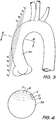
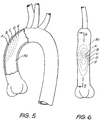
- Figs 3 to 6 show, in various orientations and views, the shape the external wall 10e of the ascending aorta 10 assumes from initial deformation (line A) through to maximum deformation (line E).
- the lines A to E show the exterior of the aorta 10 flexing along a continuous line, that preferably has the shape of a conic section, which increases in length as the counter pulsation pressure applied to the artery increases.
- An advantage of flexing the aorta in this manner is that it is caused to compress substantially without stretching, which reduces the likelihood of damage.
- the line of flexure is constantly moving so that one line of the aorta 10 is not being constantly exposed to flexural movement.
- a smoothly curved circular depression can be formed in the aorta.
- the lines A to E also show how the artery is progressively deformed along a line which lies in a plane running through the artery 10, that plane moving radially inwardly through the artery as the deformation increases.
- deformation can be caused to occur in many other different ways.
- deformation can be caused by a patch device inserted into the radially outer arc of the ascending aorta.
- the device includes a means for applying pressure to the wall or patch which, when the wall or patch is fully invaginated, forms a shape which is a mirror image of the section of the wall or patch which as been invaginated before it was so invaginated.
- FIG. 7 Another embodiment of a device for assisting the functioning of a heart according to the present invention will now be described in relation to Figs. 7 to 12 .
- Like reference numerals will be used to indicate like features used in describing to the preceding embodiment.
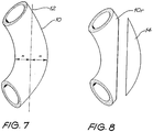
- Fig. 7 is a schematic side view of a portion of ascending aorta 10.
- Line 12 is a resection line passing through the diameter of the midpoint cross section of the aorta 10 (see also Fig. 12 ).
- Fig. 8 is a schematic view of the resected aorta 10r after cutting the aorta 10 along the resection line 12 and removal of a resected portion 14.
- Fig. 9 is a schematic side view of a heart assist device 16 in accordance with another embodiment of the invention.
- the device 16 has a relatively inelastic, preferably plastic, shell 17 and a flexible membrane 18 sealingly attached to the periphery of the shell 17.
- the membrane 18 defines an inflatable space 19 between it and the interior of the shell 17.
- the shell 17 also has an inlet/outlet port 20 which is adapted for connection to a motive means that can periodically introduce, and withdraw, a fluid (eg. a gas such as helium or a liquid such as a saline solution or an oil) to and from the space 19 in counter-pulsation with the patient's heart rhythm.
- a fluid eg. a gas such as helium or a liquid such as a saline solution or an oil
- Fig. 9 illustrates the position of the membrane 18 relative to the shell 17 when fluid has been withdrawn from the space 19 and the membrane 18 has been retracted (18r in Figs 11 and 12).
- Fig. 10 illustrates the position of the membrane 18 relative to the shell 17 after fluid has been introduced into the space 19 and the membrane 18 has been expanded (18e in Figs 11 and 12 ). When the membrane 18 is expanded it is close to, but not abutting, the opposite interior wall of the aorta 10r.
- the shell 17 has a peripheral edge of common shape to the opening formed in the aorta 10r after removal of the resected portion 14. This permits the device 16 to be attached to the resected aorta 10r by stitching between the periphery of the shell 17 and the periphery of the opening in the resected aorta 10r, as indicated by stitches 22 in Fig. 11 .
- the motive means include a fluid reservoir and a pump means adapted to pump the fluid from, the fluid reservoir to the port 20, and thus the space 19 between the interior of the shell 17 and the flexible membrane 18, and then withdrawn same, to expand (18e) and retract (18r) the membrane 18 as indicated in Figs 5 and 6 .
- Suitable implantable fluid reservoirs and pump means are disclosed in the applicant's international PCT patent application Nos. PCT/AUOO/00654 and PCT/AUO2/00974 , which are hereby incorporated by cross reference.
- the motive means is periodically actuated to introduce fluid into the space 19 in synchrony with the diastole period to reduce the interior volume of the aorta 10r and thereby provide additional pumping of the blood in the aorta 10r to assist the functioning of the heart.
- This introduction of fluid is alternated with periodic withdrawal of the fluid from the space 19 to allow the aorta 10r to return to its normal interior volume.
- the introduction of fluid expands the membrane 18 to be close to, but not abutting, the opposite interior wall of the aorta 10r. This maximises pumping volume without risk of the membrane 18 contacting and damaging the aorta 10r.
- the heart assist device 16 includes a component, namely the membrane 18, which is blood contacting.
- the membrane 18 is blood contacting.
- the previously described disadvantages of blood contacting are minimised by the present invention as when the fluid is withdrawn from the space 19 the membrane 18 is drawn into a shape substantially replicating the original (now resected) aorta wall.
- no eddies or pockets are introduced into the blood flow path that may disrupt blood flow when the device 16 is not activated thereby substantially reducing clot risk.
- the device 16 can be deactivated with the membrane 18 in the retracted position (see Fig. 9 and 18r in Figs 11 and 12 ) allowing natural blood flow there through.
- heart assist devices have been proposed that function in parallel to the aorta and which receive the full diverted flow of blood originally intended for to the aorta. These devices can not be deactivated unlike the device according to the present invention.
- the device 16 in a position vacated by the resected portion 14 of the aorta 10 it achieves a relatively high pumping volume for a relatively low device volume.
- the flexible membrane 18 is preferably manufactured from a polyurethane or a polyurethane-polysiloxane block co-polymer material or other similar material, which encourages ingrowth of the passing blood cells and can eventually create a new "natural" cell lining.
- the device according to the present invention is also particularly advantageous for use in patients whose aortas have become diseased as the device can be implanted in place of the resected damaged section.
- FIG. 13 to 16 A further embodiment of the device for assisting the functioning of a heart according to the present invention will now be described in relation to Figs. 13 to 16 .
- Like reference numerals will be used to indicate like features used in describing to the preceding embodiment.
- This embodiment is particularly suitable for use in patients having a naturally small aorta or an aorta that has shrunk through heart disease or the like.
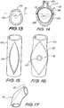
- Fig. 13 is a schematic cross sectional end view of a reduced diameter resected aorta 10r showing resection line 12 and resected portion 14.
- the periphery of the opening formed by removing the resected portion 14 is denoted 24 in Fig. 15.
- Fig. 14 shows the resected aorta 10r after its included angle ⁇ has been increased to ⁇ + so as to open or stretch out the opening 24 in the aorta 10r.
- Such stretching allows the attachment of a heart assist device 16 of a similar size to that used in a healthy aorta.
- the effective cross section of the aorta available for pumping by the membrane 18 can be increased. For example, from about 707mm 2 at an original diameter of 30mm to about 1257mm 2 at a stretched diameter of 40mm. This results in a corresponding increase in the pumping volume of the aorta 10r.
- Fig 17 is a schematic side view of an ascending aorta 10 showing an alternatively positioned resection line 12.
- the resection line 12 is angled towards the top of the aorta 10 to resect the upper, radially outer arc of the aorta 10.
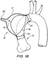
- FIG. 18 A further embodiment of a device for assisting the functioning of a heart according to the present invention will now be described in relation to Fig 18 .
- Like reference numerals will be used to indicate like features used in describing to the preceding embodiments.
- the heart assist device is a patch device 16 attachable to the ends of the aorta 10, at stitches 22, formed by removing a length of the aorta.
- the patch device 10 is in the general shape of a truncated toroid with an externally facing hump that forms the inflatable space 19.
- the membrane 18 is attached to the patch device 16 about the periphery of the hump.
- the hump is disposed external to a line on the radially outer side, or passing through, the diameter of the mid point cross section of the aorta 10.
- the flexible membrane 18 substantially replicates the shape of the interior of the hump when the fluid is withdrawn from the space 19.
- the membrane 18, when the fluid is introduced into the space 19, is expanded close to, but not abutting, the adjacent interior wall of the aorta, as is shown in phantom line.
- the heart assist devices described above are suitable for short and/or long term treatment for heart failure and/or myocardial ischemia.
Landscapes
- Health & Medical Sciences (AREA)
- Heart & Thoracic Surgery (AREA)
- Engineering & Computer Science (AREA)
- Cardiology (AREA)
- Life Sciences & Earth Sciences (AREA)
- Anesthesiology (AREA)
- Biomedical Technology (AREA)
- Hematology (AREA)
- Mechanical Engineering (AREA)
- Animal Behavior & Ethology (AREA)
- General Health & Medical Sciences (AREA)
- Public Health (AREA)
- Veterinary Medicine (AREA)
- Vascular Medicine (AREA)
- Prostheses (AREA)
- External Artificial Organs (AREA)
- Electrotherapy Devices (AREA)
Claims (10)
- Vorrichtung (16) zur Unterstützung der Funktion des Herzens eines Patienten, wobei die Vorrichtung beinhaltet:eine Aortenkompressionseinrichtung (18), die ausgebildet ist, um bei Betätigung eine Aorta zu komprimieren;eine Bewegungseinrichtung, um die Aortenkompressionseinrichtung periodisch anzuschalten und auszuschalten, und zwar in Gegenpulsation zum Herzrhythmus des Patienten,dadurch gekennzeichnet, dass die Vorrichtung weiter aufweist:eine unelastische Umwicklung (21), um die Vorrichtung an Ort und Stelle an der radial äußeren Seite einer Aorta ascendens zu halten,wobei die Aortenkompressionseinrichtung ausgebildet ist, lediglich einen Teil eines Umfangs der Aorta zu komprimieren, derart, dass bewirkt wird, dass die Aorta entlang einer zusammenhängenden Linie gebogen wird, deren Länge mit zunehmender Kompression zunimmt.
- Vorrichtung nach Anspruch 1, wobei die Aortenkompressionseinrichtung ausgebildet ist, um weniger als die Hälfte des Umfangs der Aorta zu komprimieren.
- Vorrichtung nach Anspruch 1 oder 2, wobei die Aortenkompressionseinrichtung eine mechanische Vorrichtung ist, die bei Betätigung in komprimierenden Kontakt mit der Außenseite der Aorta gebracht wird.
- Vorrichtung nach Anspruch 1 oder 2, wobei die Aortenkompressionseinrichtung eine flexible Membran (18) beinhaltet, die bei Befüllung in komprimierenden Kontakt mit der Außenseite der Aorta gebracht wird.
- Vorrichtung nach Anspruch 1, wobei die Linie die Gestalt eines konischen Querschnittes (A, B, C, D, E) hat.
- Vorrichtung nach Anspruch 1, wobei die Aortenkompressionseinrichtung in der Aorta eine sanft gekrümmte eiförmige Vertiefung (A, B, C, D, E) bewirkt, wenn sie sich, bei Verwendung, in eine Position einer maximalen Verformung der Aorta bewegt.
- Vorrichtung nach Anspruch 1, wobei die Aortenkompressionseinrichtung ausgebildet ist, periodisch eine verformende Kraft auf einen gekrümmten Abschnitt der Aorta aufzubringen, und zwar in Richtung im Wesentlichen senkrecht zu einer Tangente der radial äußeren Fläche der Längsrichtungskrümmung in der Aorta, wobei die verformende Kraft solcher Art ist, dass die Aorta progressiv entlang einer Linie (A, B, C, D, E) verformt wird, die in einer durch die Aorta verlaufenden Ebene liegt, wobei mit zunehmender Verformung die Ebene sich radial nach innen durch die Aorta hindurch bewegt.
- Vorrichtung nach Anspruch 1, wobei die Aortenkompressionseinrichtung einen befüllbaren Ballon aufweist, der sich, in Verwendung, um weniger als eine Hälfte des Umfangs der Aorta erstreckt, und wobei die Bewegungseinrichtung konfiguriert ist, den Ballon zu befüllen, wobei der Ballon eine im Wesentlichen unelastische äußere Schicht und eine innere Schicht mit einer Gestalt aufweist, die, wenn der Ballon entleert ist, sanft gekrümmt ist und so ausgebildet ist, dass sie direkt hin zum Lumen der Aorta gerichtet ist.
- Vorrichtung nach Anspruch 1, wobei, in Verwendung, die Kompressionseinrichtung ein Einstülpen der Wand der Aorta bewirkt, wobei die Kompressionseinrichtung, wenn die Wand vollständig eingestülpt ist, eine Gestalt hat, die im Wesentlichen ein Spiegelbild der einem Einstülpen unterzogenen Wand vor deren Einstülpung ist.
- Vorrichtung nach Anspruch 9, wobei die Kompressionseinrichtung ein Ballon ist.
Applications Claiming Priority (3)
| Application Number | Priority Date | Filing Date | Title |
|---|---|---|---|
| AU2002952691 | 2002-11-15 | ||
| AU2002952691A AU2002952691A0 (en) | 2002-11-15 | 2002-11-15 | Heart assist device utilising aortic deformation |
| PCT/AU2003/001458 WO2004045677A1 (en) | 2002-11-15 | 2003-11-06 | Heart assist device utilising aortic deformation |
Publications (3)
| Publication Number | Publication Date |
|---|---|
| EP1560614A1 EP1560614A1 (de) | 2005-08-10 |
| EP1560614A4 EP1560614A4 (de) | 2014-03-05 |
| EP1560614B1 true EP1560614B1 (de) | 2017-05-03 |
Family
ID=28796077
Family Applications (1)
| Application Number | Title | Priority Date | Filing Date |
|---|---|---|---|
| EP03769065.8A Expired - Lifetime EP1560614B1 (de) | 2002-11-15 | 2003-11-06 | Herzunterstützungsvorrichtung unter verwendung von aortendeformation |
Country Status (5)
| Country | Link |
|---|---|
| US (3) | US7347811B2 (de) |
| EP (1) | EP1560614B1 (de) |
| JP (1) | JP4606169B2 (de) |
| AU (1) | AU2002952691A0 (de) |
| WO (1) | WO2004045677A1 (de) |
Families Citing this family (55)
| Publication number | Priority date | Publication date | Assignee | Title |
|---|---|---|---|---|
| AUPQ090499A0 (en) | 1999-06-10 | 1999-07-01 | Peters, William S | Heart assist device and system |
| AUPR669001A0 (en) | 2001-07-30 | 2001-08-23 | Sunshine Heart Company Pty Ltd | A fluid pressure generating means |
| ATE409057T1 (de) | 2002-02-11 | 2008-10-15 | Antares Pharma Inc | Intradermales injektionsgerät |
| AU2002952691A0 (en) * | 2002-11-15 | 2002-11-28 | Sunshine Heart Company Pty Ltd | Heart assist device utilising aortic deformation |
| US8721515B2 (en) * | 2003-01-31 | 2014-05-13 | L-Vad Technology, Inc. | Rigid body aortic blood pump implant |
| US8540618B2 (en) | 2003-01-31 | 2013-09-24 | L-Vad Technology, Inc. | Stable aortic blood pump implant |
| WO2005041783A1 (en) * | 2003-10-30 | 2005-05-12 | Sunshine Heart Company Pty Ltd | A wrap |
| US20070093684A1 (en) * | 2003-10-30 | 2007-04-26 | Sunshine Heart Company Pty Ltd. | Extra-aortic patch |
| WO2005042089A1 (en) | 2003-10-31 | 2005-05-12 | Sunshine Heart Company Pty Ltd | Synchronisation control system |
| US7887478B2 (en) * | 2003-10-31 | 2011-02-15 | Sunshine Heart Company Pty Ltd | Percutaneous gas-line |
| CN1878581B (zh) * | 2003-11-11 | 2010-07-07 | 阳光心脏有限公司 | 用于心脏辅助装置的致动器 |
| WO2005074384A2 (en) * | 2004-02-10 | 2005-08-18 | Yossi Gross | Extracardiac blood flow amplification device |
| EP1720584B1 (de) * | 2004-03-02 | 2020-11-18 | Peter William Walsh | Gefäss- oder sackwand-behandlung und herzunterstützungsvorrichtung |
| US7513864B2 (en) * | 2004-07-09 | 2009-04-07 | Kantrowitz Allen B | Synchronization system between aortic valve and cardiac assist device |
| WO2006079064A1 (en) | 2005-01-24 | 2006-07-27 | Antares Pharma, Inc. | Prefilled needle assisted jet injector |
| US7544160B2 (en) * | 2005-02-10 | 2009-06-09 | Yossi Gross | Extracardiac blood flow amplification device |
| EP1933897A4 (de) * | 2005-10-14 | 2009-07-29 | Continence Control Systems Int | Verfahren und gerät zur behandlung einer herzerkrankung |
| US8251947B2 (en) | 2006-05-03 | 2012-08-28 | Antares Pharma, Inc. | Two-stage reconstituting injector |
| US8196580B2 (en) * | 2006-05-11 | 2012-06-12 | Yossi Gross | Implantable respiration therapy device |
| EP2054103B1 (de) | 2006-08-21 | 2019-05-29 | Sunshine Heart Company Pty Ltd | Verbesserter wickel für eine herzunterstützende vorrichtung |
| GB0718943D0 (en) * | 2007-09-28 | 2007-11-07 | Univ Nottingham | Mechanical support |
| EP3581224A1 (de) | 2008-08-05 | 2019-12-18 | Antares Pharma, Inc. | Injektor mit mehrfachdosierung |
| AU2010226442A1 (en) | 2009-03-20 | 2011-10-13 | Antares Pharma, Inc. | Hazardous agent injection system |
| GB201005198D0 (en) | 2010-03-26 | 2010-05-12 | Univ Aston | Pulsatile blood pump |
| CN102939117B (zh) | 2010-04-02 | 2015-12-02 | 阳光心脏有限公司 | 组合心脏辅助系统、方法和装置 |
| US9220660B2 (en) | 2011-07-15 | 2015-12-29 | Antares Pharma, Inc. | Liquid-transfer adapter beveled spike |
| US8496619B2 (en) | 2011-07-15 | 2013-07-30 | Antares Pharma, Inc. | Injection device with cammed ram assembly |
| EP2833944A4 (de) | 2012-04-06 | 2016-05-25 | Antares Pharma Inc | Verabreichung von testosteron-zusammensetzungen durch nadelgestützte düseninjektion |
| US9364610B2 (en) | 2012-05-07 | 2016-06-14 | Antares Pharma, Inc. | Injection device with cammed ram assembly |
| PT2953667T (pt) | 2013-02-11 | 2020-01-28 | Antares Pharma Inc | Dispositivo de injeção a jato auxiliado por agulha tendo força de gatilho reduzida |
| JP6030803B2 (ja) | 2013-03-11 | 2016-11-24 | アンタレス・ファーマ・インコーポレーテッド | ピニオンシステムを有する用量注射器 |
| CN105246522B (zh) | 2013-03-15 | 2017-10-20 | 华思科公司 | 胸主动脉心室辅助系统 |
| JP6027470B2 (ja) * | 2013-03-19 | 2016-11-16 | 厚夫 森 | 血管パッチ |
| GB201310578D0 (en) | 2013-06-13 | 2013-07-31 | Univ Nottingham Trent | Electroactive actuators |
| US9814816B2 (en) | 2013-06-21 | 2017-11-14 | Corvivo, Inc. | Artificial ventricles |
| US9320841B2 (en) | 2013-06-21 | 2016-04-26 | Corvivo, Inc. | Ventricular assist device |
| US9833551B2 (en) * | 2015-04-29 | 2017-12-05 | The Texas A&M University System | Fully implantable direct cardiac and aortic compression device |
| US10583292B2 (en) | 2016-10-18 | 2020-03-10 | Chf Solutions, Inc. | Electronic neuromodulatory emulation of extra- and intra-aortic balloon pump counter-pulsation systems and methods |
| EP3634528B1 (de) | 2017-06-07 | 2023-06-07 | Shifamed Holdings, LLC | Intravaskuläre fluidbewegungsvorrichtungen, systeme und verwendungsverfahren |
| US11511103B2 (en) | 2017-11-13 | 2022-11-29 | Shifamed Holdings, Llc | Intravascular fluid movement devices, systems, and methods of use |
| EP3746149B1 (de) | 2018-02-01 | 2025-08-06 | Shifamed Holdings, LLC | Intravaskuläre blutpumpen |
| NL2021401B1 (en) * | 2018-07-27 | 2020-01-31 | Stichting Katholieke Univ | Heart support device with directional flow assist |
| WO2020028537A1 (en) | 2018-07-31 | 2020-02-06 | Shifamed Holdings, Llc | Intravascaular blood pumps and methods of use |
| WO2020073047A1 (en) | 2018-10-05 | 2020-04-09 | Shifamed Holdings, Llc | Intravascular blood pumps and methods of use |
| NL2022660B1 (en) | 2019-03-01 | 2020-09-15 | Stichting Katholieke Univ | Heart Assist Device |
| JP7286380B2 (ja) * | 2019-04-01 | 2023-06-05 | 国立大学法人 東京大学 | 医用画像処理装置及び医用画像処理プログラム |
| WO2021011473A1 (en) | 2019-07-12 | 2021-01-21 | Shifamed Holdings, Llc | Intravascular blood pumps and methods of manufacture and use |
| US11654275B2 (en) | 2019-07-22 | 2023-05-23 | Shifamed Holdings, Llc | Intravascular blood pumps with struts and methods of use and manufacture |
| US12465748B2 (en) | 2019-08-07 | 2025-11-11 | Supira Medical, Inc. | Catheter blood pumps and collapsible pump housings |
| WO2021062260A1 (en) | 2019-09-25 | 2021-04-01 | Shifamed Holdings, Llc | Catheter blood pumps and collapsible blood conduits |
| EP4501393A3 (de) | 2019-09-25 | 2025-04-09 | Shifamed Holdings, LLC | Katheterblutpumpen und zusammenklappbare pumpengehäuse |
| US11724089B2 (en) | 2019-09-25 | 2023-08-15 | Shifamed Holdings, Llc | Intravascular blood pump systems and methods of use and control thereof |
| EP4072650A4 (de) * | 2019-12-11 | 2024-01-10 | Shifamed Holdings, LLC | Absteigende aorten- und hohlvenenblutpumpen |
| EP4077947A4 (de) | 2019-12-19 | 2024-01-10 | Shifamed Holdings, LLC | Intravaskuläre blutpumpen, motoren und fluidsteuerung |
| NL2028130B1 (en) | 2021-05-03 | 2022-11-10 | Cardiacbooster B V | Cardiac assist device with high frequency operation |
Family Cites Families (177)
| Publication number | Priority date | Publication date | Assignee | Title |
|---|---|---|---|---|
| US283660A (en) | 1883-08-21 | Compression-cock | ||
| US929571A (en) | 1908-09-19 | 1909-07-27 | Dubied & Cie Sa E | Valve for pneumatic tires. |
| US1576397A (en) | 1925-07-18 | 1926-03-09 | Yanagi Tokujiro | Tourniquet |
| US1719316A (en) | 1927-03-25 | 1929-07-02 | Central Valve Mfg Co | Valve |
| DE1541311A1 (de) | 1965-11-24 | 1969-09-11 | Zacouto Dr Med Fred | Wenigstens teilweise in den Organismen einpflanzbare Einrichtung zum Ausgleich einer Herzinsuffizienz bei hoeheren Saeugetieren |
| US3467077A (en) | 1966-06-30 | 1969-09-16 | Dupaco Inc | Sphygmomanometric cuff |
| US3597766A (en) | 1968-07-11 | 1971-08-10 | Atomic Energy Commission | Artificial heart pumping system powered by a modified stirling cycle engine-compressor having a freely reciprocable displacer piston |
| US3552383A (en) | 1969-01-08 | 1971-01-05 | Ibm | Method and system for estimation of arterial pressure |
| US4014318A (en) | 1973-08-20 | 1977-03-29 | Dockum James M | Circulatory assist device and system |
| US4010318A (en) * | 1975-05-20 | 1977-03-01 | Rca Corporation | Probe forming electron optical column having means for examining magnified image of the probe source |
| US4051840A (en) * | 1976-01-05 | 1977-10-04 | Sinai Hospital Of Detroit | Dynamic aortic patch |
| US4046137A (en) | 1976-08-11 | 1977-09-06 | Avco Corporation | Solenoid operated blood pump drive system |
| US4195623A (en) * | 1977-07-21 | 1980-04-01 | Phillips Steven J | Parallel aorta balloon pump and method of using same |
| US4176411A (en) * | 1977-11-28 | 1979-12-04 | Runge Thomas M | Cardiac assist device employing electrically stimulated artificial muscle |
| US4236482A (en) | 1978-06-09 | 1980-12-02 | Champion International Corporation | Apparatus for applying sealing material to envelopes |
| US4277706A (en) | 1979-04-16 | 1981-07-07 | Nu-Tech Industries, Inc. | Actuator for heart pump |
| US4304225A (en) * | 1979-04-30 | 1981-12-08 | Lloyd And Associates | Control system for body organs |
| FR2458288A1 (fr) | 1979-06-11 | 1981-01-02 | Belenger Jacques | Pompe medicale destinee a l'assistance cardiaque pulsative |
| US4256094A (en) | 1979-06-18 | 1981-03-17 | Kapp John P | Arterial pressure control system |
| US4457673A (en) | 1980-11-28 | 1984-07-03 | Novacor Medical Corporation | Pump and actuator mechanism |
| FR2502499B1 (fr) | 1981-03-27 | 1987-01-23 | Farcot Jean Christian | Appareil pour la retroperfusion sanguine, destine notamment au traitement d'infarctus par injection de sang arteriel dans le sinus coronaire |
| US4428378A (en) | 1981-11-19 | 1984-01-31 | Medtronic, Inc. | Rate adaptive pacer |
| US4454891A (en) | 1982-03-09 | 1984-06-19 | Emerson Electric Co. (H & H Precision Products Division) | Air gap drain module for use in a reverse osmosis system |
| DE3224016C2 (de) * | 1982-06-28 | 1986-03-27 | Akzo Gmbh, 5600 Wuppertal | Reinheitskontrolle durch Messung der elektrischen Leitfähigkeit |
| US4515587A (en) | 1983-02-14 | 1985-05-07 | Smec, Inc. | IAB having apparatus for assuring proper balloon inflation and deflation |
| US4771765A (en) * | 1984-02-21 | 1988-09-20 | Choy Daniel S J | Heart assist device and method of use |
| US4630597A (en) * | 1984-04-30 | 1986-12-23 | Adrian Kantrowitz | Dynamic aortic patch for thoracic or abdominal implantation |
| US4886490A (en) | 1984-05-14 | 1989-12-12 | Surgical Systems & Instruments, Inc. | Atherectomy catheter system and method of using the same |
| US4583523A (en) | 1984-07-02 | 1986-04-22 | Lloyd & Associates | Implantable heart assist device and method of implanting same |
| US4594731A (en) | 1984-11-09 | 1986-06-10 | University Of Utah | Electronic stethoscope |
| US4881939A (en) | 1985-02-19 | 1989-11-21 | The Johns Hopkins University | Implantable helical cuff |
| FR2577423B1 (fr) | 1985-02-20 | 1989-05-05 | Gilles Karcher | Pompe d'assistance circulatoire et coronaire a ballonnets intra-aortiques |
| DE3506791A1 (de) | 1985-02-22 | 1986-08-28 | Biotronik Meß- und Therapiegeräte GmbH & Co Ingenieurbüro Berlin, 1000 Berlin | Herzschrittmacher mit physiologischer steuerung |
| JPS61232859A (ja) | 1985-04-05 | 1986-10-17 | 呉羽化学工業株式会社 | 医用ポンプ装置 |
| US4813952A (en) * | 1985-08-01 | 1989-03-21 | Medtronic, Inc. | Cardiac assist device |
| EP0216042B1 (de) | 1985-08-01 | 1991-03-06 | Medtronic, Inc. | Vorrichtung zur Herzunterstützung |
| DE3535504A1 (de) | 1985-10-04 | 1987-04-09 | Siemens Ag | Herzschrittmacher |
| CH667701A5 (de) | 1985-11-05 | 1988-10-31 | Hans Meyer | Pumpe. |
| US4676482A (en) | 1986-04-28 | 1987-06-30 | Rexnord Inc. | Valve seat insert |
| SE454942B (sv) | 1986-05-22 | 1988-06-13 | Astra Tech Ab | Hjerthjelpanordning for inoperation i brosthalan |
| US4925443A (en) | 1987-02-27 | 1990-05-15 | Heilman Marlin S | Biocompatible ventricular assist and arrhythmia control device |
| US4979936A (en) * | 1987-04-28 | 1990-12-25 | Trustees Of The University Of Pennsylvania | Autologous biologic pump motor |
| US4822357A (en) | 1987-04-29 | 1989-04-18 | Articor Limited | Auxiliary artificial heart |
| US4809676A (en) * | 1987-12-28 | 1989-03-07 | Freeman Maynard L | Heart assist device and method of implanting it |
| JPH02297381A (ja) | 1988-10-05 | 1990-12-07 | Abiomed Lp | 心機能助成気嚢及びその挿入方法 |
| US5069662A (en) | 1988-10-21 | 1991-12-03 | Delcath Systems, Inc. | Cancer treatment |
| US5089017A (en) | 1989-01-17 | 1992-02-18 | Young David B | Drive system for artificial hearts and left-ventricular assist devices |
| FR2645739A1 (fr) | 1989-04-14 | 1990-10-19 | Vm Tech Sa | Dispositif d'assistance cardiaque et son utilisation |
| EP0923954A3 (de) | 1989-06-20 | 1999-08-11 | Btg International Limited | Massnahmen zur Verbesserung der Blutströmung |
| US5267940A (en) * | 1989-11-29 | 1993-12-07 | The Administrators Of The Tulane Educational Fund | Cardiovascular flow enhancer and method of operation |
| US5477864A (en) | 1989-12-21 | 1995-12-26 | Smith & Nephew Richards, Inc. | Cardiovascular guidewire of enhanced biocompatibility |
| DE4020120A1 (de) | 1990-06-25 | 1991-01-31 | Klaus Prof Dr Ing Affeld | Medizinische vorrichtung zur erzeugung eines alternierenden volumenstroms fuer den antrieb von implantierbaren blutpumpen |
| ES2020787A6 (es) | 1990-07-20 | 1991-09-16 | Figuera Aymerich Diego | Bomba intra-ventricular expansible de asistencia circulatoria. |
| RU1767723C (ru) | 1990-08-14 | 1995-01-27 | Кирово-Чепецкий химический комбинат | Протез клапана сердца |
| CA2052310A1 (en) | 1990-10-09 | 1992-04-10 | Thomas L. Foster | Surgical access sheath |
| US5205810A (en) | 1990-10-15 | 1993-04-27 | Medtronic, Inc. | Muscle powered cardiac assist system |
| WO1992008500A1 (en) | 1990-11-09 | 1992-05-29 | Mcgill University | Cardiac assist method and apparatus |
| US5383915A (en) | 1991-04-10 | 1995-01-24 | Angeion Corporation | Wireless programmer/repeater system for an implanted medical device |
| US5286217A (en) * | 1991-08-15 | 1994-02-15 | Foxconn International | Electrical connector with improved latch mechanism |
| US5222980A (en) * | 1991-09-27 | 1993-06-29 | Medtronic, Inc. | Implantable heart-assist device |
| US5344385A (en) | 1991-09-30 | 1994-09-06 | Thoratec Laboratories Corporation | Step-down skeletal muscle energy conversion system |
| EP0610428A1 (de) | 1991-10-31 | 1994-08-17 | Medtronic, Inc. | System zur überwachung und steuerung eines muskels |
| US5360445A (en) | 1991-11-06 | 1994-11-01 | International Business Machines Corporation | Blood pump actuator |
| US5251621A (en) | 1991-12-18 | 1993-10-12 | Telectronics Pacing Systems, Inc. | Arrhythmia control pacer using skeletal muscle cardiac graft stimulation |
| US5273518A (en) | 1992-01-31 | 1993-12-28 | Medtronic, Inc. | Cardiac assist apparatus |
| US5300111A (en) | 1992-02-03 | 1994-04-05 | Pyxis, Inc. | Total artificial heart |
| US5814012A (en) | 1992-03-16 | 1998-09-29 | Birtcher Medical Systems, Inc. | Method and apparatus for relieving excess insufflation pressure |
| CA2111588A1 (en) | 1992-04-17 | 1993-10-28 | Yoshiharu Kiyota | Internal cardiac assist apparatus |
| US5337752A (en) | 1992-05-21 | 1994-08-16 | Mcg International, Inc. | System for simultaneously producing and synchronizing spectral patterns of heart sounds and an ECG signal |
| US5676651A (en) | 1992-08-06 | 1997-10-14 | Electric Boat Corporation | Surgically implantable pump arrangement and method for pumping body fluids |
| SG47123A1 (en) | 1993-03-15 | 1998-03-20 | Omron Tateisi Electronics Co | Cuff for blood pressure meter |
| IL106738A (en) | 1993-08-19 | 1998-02-08 | Mind E M S G Ltd | Device for external correction of deficient valves in venous junctions |
| JPH08504120A (ja) | 1993-08-25 | 1996-05-07 | アポロ キャメラ,リミテッド ライアビリティー カンパニー | 外科用結さつクリップ |
| DE69419420T2 (de) | 1993-09-10 | 1999-11-18 | Ottawa Heart Institute Research Corp., Ottawa | Elektrohydraulisches ventrikulares unterstützungssystem |
| US6045496A (en) * | 1994-04-15 | 2000-04-04 | Allegheny-Singer Research Institute | Occluder device and method of making |
| US5843170A (en) | 1994-09-02 | 1998-12-01 | Ahn; Sam Seunghae | Apparatus and method for performing aneurysm repair |
| US5607378A (en) | 1994-11-21 | 1997-03-04 | Winston; Edith | Method of exercising a selected muscle |
| DE19504085C2 (de) | 1995-02-08 | 1997-07-10 | Osypka Peter | Vorrichtung zur Unterstützung der Herztätigkeit mit Hilfe eines Ballons |
| US5554177A (en) | 1995-03-27 | 1996-09-10 | Medtronic, Inc. | Method and apparatus to optimize pacing based on intensity of acoustic signal |
| US5647380A (en) * | 1995-06-07 | 1997-07-15 | W. L. Gore & Associates, Inc. | Method of making a left ventricular assist device |
| FR2744021B1 (fr) | 1996-01-26 | 1998-04-03 | Franchi Pierre | Pompe d'assistance cardiaque implantable du type a ballonet de contrepression |
| FR2744924B1 (fr) * | 1996-02-21 | 1998-04-24 | Franchi Pierre | Dispositif generateur/regulateur de pression pour pompe d'assistance cardiaque implantable du type a ballonnet de contrepression |
| WO1997040755A1 (en) | 1996-04-29 | 1997-11-06 | W.L. Gore & Associates, Inc. | Device for restoring competence to venous valves |
| US6059750A (en) | 1996-08-01 | 2000-05-09 | Thomas J. Fogarty | Minimally invasive direct cardiac massage device and method |
| SE9603573D0 (sv) | 1996-09-30 | 1996-09-30 | Pacesetter Ab | Implantable medecal device |
| US5827171A (en) | 1996-10-31 | 1998-10-27 | Momentum Medical, Inc. | Intravascular circulatory assist device |
| US5820542A (en) | 1996-10-31 | 1998-10-13 | Momentum Medical, Inc. | Modified circulatory assist device |
| US5888242A (en) | 1996-11-01 | 1999-03-30 | Nimbus, Inc. | Speed control system for implanted blood pumps |
| US5792195A (en) | 1996-12-16 | 1998-08-11 | Cardiac Pacemakers, Inc. | Acceleration sensed safe upper rate envelope for calculating the hemodynamic upper rate limit for a rate adaptive cardiac rhythm management device |
| US7107103B2 (en) | 1997-02-26 | 2006-09-12 | Alfred E. Mann Foundation For Scientific Research | Full-body charger for battery-powered patient implantable device |
| US5833655A (en) | 1997-05-15 | 1998-11-10 | L. Vad Technology, Inc. | Percutaneous access device having removable turret assembly |
| JPH10328297A (ja) | 1997-06-02 | 1998-12-15 | Buaayu:Kk | 心機能補助装置 |
| US5921965A (en) | 1997-07-07 | 1999-07-13 | New York University | Tubing device for antibiotic administration through central venous catheters |
| IL121316A (en) | 1997-07-15 | 2001-07-24 | Litana Ltd | A medical device for planting in an alloy body with memory properties |
| FR2766373B1 (fr) | 1997-07-24 | 1999-08-27 | Commissariat Energie Atomique | Dispositif d'assistance cardiaque ventriculaire a contre-pulsation |
| US5975140A (en) | 1997-07-28 | 1999-11-02 | Lin; Ching-Yi | Gooseneck faucet |
| FR2767874A1 (fr) | 1997-08-26 | 1999-02-26 | Commissariat Energie Atomique | Actionneur pour exercer une pression de fluide, a faible consommation d'energie |
| JP2003521260A (ja) | 1997-09-30 | 2003-07-15 | エル.ヴァド テクノロジー,インコーポレイテッド | 心臓血管系サポートコントロールシステム |
| US5980448A (en) | 1998-01-28 | 1999-11-09 | Vascor, Inc. | Single chamber blood pump |
| US6042532A (en) | 1998-03-09 | 2000-03-28 | L. Vad Technology, Inc. | Pressure control system for cardiac assist device |
| JP4051812B2 (ja) | 1998-04-13 | 2008-02-27 | 株式会社ジェイ・エム・エス | 制御機能を備えた体外循環装置 |
| WO2000012168A1 (en) | 1998-09-01 | 2000-03-09 | Cardeon Corporation | System and methods for catheter procedures with circulatory support in high risk patients |
| US6251061B1 (en) | 1998-09-09 | 2001-06-26 | Scimed Life Systems, Inc. | Cardiac assist device using field controlled fluid |
| US6132636A (en) | 1998-10-23 | 2000-10-17 | Allied Signal Inc | Leak-detecting refrigerant compositions containing oxazolyl-coumarin dyes |
| US6030366A (en) | 1998-11-09 | 2000-02-29 | Safety Syringes, Inc. | Syringe guard system for a unit dose syringe |
| US6432039B1 (en) | 1998-12-21 | 2002-08-13 | Corset, Inc. | Methods and apparatus for reinforcement of the heart ventricles |
| US6226843B1 (en) | 1999-02-25 | 2001-05-08 | Design Standards Corporation | Ligating clip |
| US6210318B1 (en) | 1999-03-09 | 2001-04-03 | Abiomed, Inc. | Stented balloon pump system and method for using same |
| US20010016676A1 (en) | 1999-04-21 | 2001-08-23 | Jonathan Williams | Intra-aortic balloon pump condensation prevention system |
| US6210319B1 (en) | 1999-04-21 | 2001-04-03 | Datascope Investment Corp. | Intra-aortic balloon pump condensation prevention system |
| US6146325A (en) | 1999-06-03 | 2000-11-14 | Arrow International, Inc. | Ventricular assist device |
| AUPQ090499A0 (en) | 1999-06-10 | 1999-07-01 | Peters, William S | Heart assist device and system |
| US6553263B1 (en) | 1999-07-30 | 2003-04-22 | Advanced Bionics Corporation | Implantable pulse generators using rechargeable zero-volt technology lithium-ion batteries |
| US6471633B1 (en) * | 1999-08-23 | 2002-10-29 | L.Vad Technology, Inc. | Mechanical auxillary ventricle blood pump with reduced waist portion |
| US6585635B1 (en) | 1999-09-17 | 2003-07-01 | Core Medical, Inc. | Method and system for pericardial modification |
| US6406422B1 (en) | 2000-03-02 | 2002-06-18 | Levram Medical Devices, Ltd. | Ventricular-assist method and apparatus |
| US6643548B1 (en) | 2000-04-06 | 2003-11-04 | Pacesetter, Inc. | Implantable cardiac stimulation device for monitoring heart sounds to detect progression and regression of heart disease and method thereof |
| JP2003531687A (ja) | 2000-05-02 | 2003-10-28 | バスカ, インコーポレイテッド | 身体内または身体外に流体を汲み上げるための方法およびデバイス |
| US6572534B1 (en) | 2000-09-14 | 2003-06-03 | Abiomed, Inc. | System and method for implanting a cardiac wrap |
| AUPR031200A0 (en) | 2000-09-22 | 2000-10-12 | Sunshine Heart Company Pty Ltd | Heart assist devices, systems and methods II |
| GB0023412D0 (en) | 2000-09-23 | 2000-11-08 | Khaghani Asghar | Aortic counterpulsator |
| NL1016320C2 (nl) | 2000-10-03 | 2002-04-04 | Jozef Reinier Cornelis Jansen | Inrichting voor het aansturen van hartondersteunende apparaten. |
| US6808483B1 (en) | 2000-10-03 | 2004-10-26 | Paul A. Spence | Implantable heart assist devices and methods |
| US6616596B1 (en) | 2000-11-28 | 2003-09-09 | Abiomed, Inc. | Cardiac assistance systems having multiple layers of inflatable elements |
| US7229402B2 (en) | 2001-02-09 | 2007-06-12 | Cardiac Output Technologies, Inc. | Minimally invasive ventricular assist technology and method |
| AUPR389201A0 (en) | 2001-03-23 | 2001-04-12 | Lane, Rodney James | Improvements in design of external vendus valve stents for the correction fo incompetent vendods valves |
| EP1385455A1 (de) | 2001-05-01 | 2004-02-04 | Imperial Medical Devices Limited | Klappenprothese |
| US6626821B1 (en) | 2001-05-22 | 2003-09-30 | Abiomed, Inc. | Flow-balanced cardiac wrap |
| AUPR669001A0 (en) | 2001-07-30 | 2001-08-23 | Sunshine Heart Company Pty Ltd | A fluid pressure generating means |
| US6902540B2 (en) | 2001-08-22 | 2005-06-07 | Gerald Dorros | Apparatus and methods for treating stroke and controlling cerebral flow characteristics |
| AUPR800301A0 (en) | 2001-09-28 | 2001-10-25 | Sunshine Heart Company Pty Ltd | A method of performing a coronary artery bypass operation on a patient's beating heart |
| JP3862999B2 (ja) | 2001-11-06 | 2006-12-27 | 株式会社ミワテック | 体内埋め込み型人工心臓における経皮的情報伝送システム。 |
| US6810287B2 (en) | 2001-12-03 | 2004-10-26 | Cardiac Pacemakers, Inc. | Implantable cardiac disease management device with trigger-stored polysomnogram and phonocardiogram |
| US20040010180A1 (en) | 2002-05-16 | 2004-01-15 | Scorvo Sean K. | Cardiac assist system |
| US20040147803A1 (en) | 2002-10-07 | 2004-07-29 | Hegde Anant V. | Vascular assist device and methods |
| AU2002952730A0 (en) | 2002-11-15 | 2002-12-05 | Sunshine Heart Company Pty Ltd | An Intraluminal Inflatable Counter-pulsation Heart Assist Device |
| AU2003277983B2 (en) | 2002-11-15 | 2008-06-26 | Sunshine Heart Company Pty Ltd | Heart assist device utilising aortic deformation |
| AU2002952691A0 (en) | 2002-11-15 | 2002-11-28 | Sunshine Heart Company Pty Ltd | Heart assist device utilising aortic deformation |
| AU2002953440A0 (en) | 2002-12-19 | 2003-01-09 | Unisearch Limited | A method of treating a stiffened vessel |
| US8540618B2 (en) | 2003-01-31 | 2013-09-24 | L-Vad Technology, Inc. | Stable aortic blood pump implant |
| US20070093684A1 (en) | 2003-10-30 | 2007-04-26 | Sunshine Heart Company Pty Ltd. | Extra-aortic patch |
| WO2005041781A1 (en) | 2003-10-30 | 2005-05-12 | Sunshine Heart Company Pty Ltd | Methods and devices for tensioning a wrap around a blood vessel |
| WO2005041783A1 (en) | 2003-10-30 | 2005-05-12 | Sunshine Heart Company Pty Ltd | A wrap |
| US7887478B2 (en) | 2003-10-31 | 2011-02-15 | Sunshine Heart Company Pty Ltd | Percutaneous gas-line |
| WO2005042089A1 (en) | 2003-10-31 | 2005-05-12 | Sunshine Heart Company Pty Ltd | Synchronisation control system |
| CN1878581B (zh) | 2003-11-11 | 2010-07-07 | 阳光心脏有限公司 | 用于心脏辅助装置的致动器 |
| PL1715902T3 (pl) | 2004-01-08 | 2017-01-31 | Sullivan, Paul Joseph | Urządzenie do nieniszczącego przetłaczania płynu |
| EP1720584B1 (de) | 2004-03-02 | 2020-11-18 | Peter William Walsh | Gefäss- oder sackwand-behandlung und herzunterstützungsvorrichtung |
| DE102004023190B3 (de) | 2004-05-11 | 2005-10-20 | Ppa Technologies Ag | Vorrichtung zur epikardialen Unterstützung und/oder Übernahme der Herztätigkeit |
| US7513864B2 (en) | 2004-07-09 | 2009-04-07 | Kantrowitz Allen B | Synchronization system between aortic valve and cardiac assist device |
| KR20040072581A (ko) | 2004-07-29 | 2004-08-18 | (주)제이씨 프로텍 | 전자기파 증폭중계기 및 이를 이용한 무선전력변환장치 |
| US7532933B2 (en) | 2004-10-20 | 2009-05-12 | Boston Scientific Scimed, Inc. | Leadless cardiac stimulation systems |
| US7360558B1 (en) * | 2005-05-31 | 2008-04-22 | Jui-Chien Chen | Control valve for drinking water fountain |
| US7616990B2 (en) | 2005-10-24 | 2009-11-10 | Cardiac Pacemakers, Inc. | Implantable and rechargeable neural stimulator |
| US7962211B2 (en) | 2006-04-28 | 2011-06-14 | Medtronic, Inc. | Antenna for an external power source for an implantable medical device, system and method |
| US7738965B2 (en) | 2006-04-28 | 2010-06-15 | Medtronic, Inc. | Holster for charging pectorally implanted medical devices |
| EP2026856B1 (de) | 2006-05-31 | 2015-08-26 | VADovations, Inc. | Herzunterstützungsvorrichtung |
| EP2054103B1 (de) | 2006-08-21 | 2019-05-29 | Sunshine Heart Company Pty Ltd | Verbesserter wickel für eine herzunterstützende vorrichtung |
| US20100070019A1 (en) | 2006-10-29 | 2010-03-18 | Aneuwrap Ltd. | extra-vascular wrapping for treating aneurysmatic aorta and methods thereof |
| WO2008071223A1 (en) | 2006-12-15 | 2008-06-19 | Gaetano Azzolina | Cardiocirculatory aiding device |
| US8690870B2 (en) | 2006-12-28 | 2014-04-08 | St. Jude Medical, Atrial Fibrillation Division, Inc. | Irrigated ablation catheter system with pulsatile flow to prevent thrombus |
| US8382830B2 (en) | 2007-06-06 | 2013-02-26 | World Heart Corporation | Implantable VAD with replaceable percutaneous cable |
| US8366652B2 (en) | 2007-08-17 | 2013-02-05 | The Invention Science Fund I, Llc | Systems, devices, and methods including infection-fighting and monitoring shunts |
| US7974704B2 (en) | 2007-08-22 | 2011-07-05 | Medtronic, Inc. | Lead body constructions for implantable medical electrical leads |
| US8738147B2 (en) | 2008-02-07 | 2014-05-27 | Cardiac Pacemakers, Inc. | Wireless tissue electrostimulation |
| US8229567B2 (en) | 2008-04-30 | 2012-07-24 | Medtronic, Inc. | Concentric primary coils for inductively charging an implantable medical device, external power source and method |
| US8075531B2 (en) | 2008-07-16 | 2011-12-13 | Marvao Medical Ltd. | Modular implantable medical device |
| EP2385860B1 (de) | 2008-11-21 | 2021-01-06 | Implantica Patent Ltd. | System zur energieversorgung einer implantierbaren medizinischen vorrichtung |
| AU2010237614B2 (en) | 2009-04-16 | 2013-11-07 | Bivacor Pty Ltd | Heart pump controller |
| US8231519B2 (en) | 2009-05-20 | 2012-07-31 | Thoratec Corporation | Multi-lumen cannula |
| US20110112353A1 (en) | 2009-11-09 | 2011-05-12 | Circulite, Inc. | Bifurcated outflow cannulae |
| GB201002370D0 (en) | 2010-02-12 | 2010-03-31 | Renishaw Ireland Ltd | Percutaneous drug delivery apparatus |
| CN102939117B (zh) | 2010-04-02 | 2015-12-02 | 阳光心脏有限公司 | 组合心脏辅助系统、方法和装置 |
| WO2011156391A2 (en) | 2010-06-07 | 2011-12-15 | Thoratec Corporation | Bi-ventricular percutaneous cable |
| CN102808765B (zh) | 2011-06-01 | 2017-04-05 | 德昌电机(深圳)有限公司 | 流体泵送装置 |
| EP2557313A1 (de) | 2011-08-10 | 2013-02-13 | Berlin Heart GmbH | Rotationspumpe mit einem rotor und förderelementen |
| US9367725B2 (en) | 2011-11-03 | 2016-06-14 | Cognex Corporation | Method and apparatus for performing different decoding algorithms in different locations |
-
2002
- 2002-11-15 AU AU2002952691A patent/AU2002952691A0/en not_active Abandoned
-
2003
- 2003-11-05 US US10/702,834 patent/US7347811B2/en not_active Expired - Lifetime
- 2003-11-06 EP EP03769065.8A patent/EP1560614B1/de not_active Expired - Lifetime
- 2003-11-06 JP JP2004552261A patent/JP4606169B2/ja not_active Expired - Fee Related
- 2003-11-06 WO PCT/AU2003/001458 patent/WO2004045677A1/en not_active Ceased
-
2008
- 2008-03-07 US US12/044,853 patent/US8777833B2/en not_active Expired - Fee Related
-
2014
- 2014-06-18 US US14/307,608 patent/US9555176B2/en not_active Expired - Fee Related
Also Published As
| Publication number | Publication date |
|---|---|
| EP1560614A1 (de) | 2005-08-10 |
| US20080167515A1 (en) | 2008-07-10 |
| US20040097783A1 (en) | 2004-05-20 |
| EP1560614A4 (de) | 2014-03-05 |
| US8777833B2 (en) | 2014-07-15 |
| WO2004045677A1 (en) | 2004-06-03 |
| US7347811B2 (en) | 2008-03-25 |
| AU2002952691A0 (en) | 2002-11-28 |
| US20140296616A1 (en) | 2014-10-02 |
| JP4606169B2 (ja) | 2011-01-05 |
| JP2006520209A (ja) | 2006-09-07 |
| US9555176B2 (en) | 2017-01-31 |
Similar Documents
| Publication | Publication Date | Title |
|---|---|---|
| US9555176B2 (en) | Implantable device utilizing arterial deformation | |
| US7811221B2 (en) | Extracardiac blood flow amplification device | |
| US5192314A (en) | Synthetic intraventricular implants and method of inserting | |
| EP0415949B1 (de) | Transvalvuläre, achssymmetrische hochfrequenzblutpumpe | |
| EP2209508B1 (de) | Pulsierende blutpumpe | |
| US5273518A (en) | Cardiac assist apparatus | |
| US5848962A (en) | Device for assisting cardiac function | |
| US4051840A (en) | Dynamic aortic patch | |
| US20100152525A1 (en) | Peri-arterial blood flow booster | |
| US20030032854A1 (en) | Blood pump | |
| JP2003501180A (ja) | 心臓補助デバイス、システムおよびその方法 | |
| JPH06510686A (ja) | 皮下埋設可能な心臓援助装置 | |
| CA2349627A1 (en) | Ventricular assist device with pre-formed inflation bladder | |
| WO2011117566A1 (en) | Pulsatile blood pump | |
| WO1992008500A1 (en) | Cardiac assist method and apparatus | |
| US6149578A (en) | Piston-action intra-aortic coronary assist device | |
| JP2003517353A (ja) | 縮小されたウェスト部分を有する機械補助心室血液ポンプ | |
| US8142372B2 (en) | External left ventricular assist device for treatment of congestive heart failure | |
| AU2003277983B2 (en) | Heart assist device utilising aortic deformation | |
| US20200129685A1 (en) | Intra-aortic spiral balloon pump | |
| US20240099846A1 (en) | Minimally Invasive Heart Pump with Modular Adjustable Construct Insertion | |
| JPS6284770A (ja) | 高サイクル動脈内心臓サポ−トシステム | |
| JPH0422584B2 (de) | ||
| CN117083100A (zh) | 具有内置压力感测器的心室辅助装置 |
Legal Events
| Date | Code | Title | Description |
|---|---|---|---|
| PUAI | Public reference made under article 153(3) epc to a published international application that has entered the european phase |
Free format text: ORIGINAL CODE: 0009012 |
|
| 17P | Request for examination filed |
Effective date: 20050530 |
|
| AK | Designated contracting states |
Kind code of ref document: A1 Designated state(s): AT BE BG CH CY CZ DE DK EE ES FI FR GB GR HU IE IT LI LU MC NL PT RO SE SI SK TR |
|
| AX | Request for extension of the european patent |
Extension state: AL LT LV MK |
|
| DAX | Request for extension of the european patent (deleted) | ||
| RIN1 | Information on inventor provided before grant (corrected) |
Inventor name: WATTERSON, PETER ANDREW Inventor name: MILLER, SCOTT, HUGH Inventor name: PETERS, WILLIAM, SUTTLE |
|
| RAP1 | Party data changed (applicant data changed or rights of an application transferred) |
Owner name: SUNSHINE HEART COMPANY PTY LTD |
|
| A4 | Supplementary search report drawn up and despatched |
Effective date: 20140203 |
|
| RIC1 | Information provided on ipc code assigned before grant |
Ipc: A61M 1/10 20060101AFI20140128BHEP Ipc: A61M 1/12 20060101ALI20140128BHEP |
|
| 17Q | First examination report despatched |
Effective date: 20150624 |
|
| GRAP | Despatch of communication of intention to grant a patent |
Free format text: ORIGINAL CODE: EPIDOSNIGR1 |
|
| INTG | Intention to grant announced |
Effective date: 20160519 |
|
| GRAS | Grant fee paid |
Free format text: ORIGINAL CODE: EPIDOSNIGR3 |
|
| GRAA | (expected) grant |
Free format text: ORIGINAL CODE: 0009210 |
|
| AK | Designated contracting states |
Kind code of ref document: B1 Designated state(s): AT BE BG CH CY CZ DE DK EE ES FI FR GB GR HU IE IT LI LU MC NL PT RO SE SI SK TR |
|
| REG | Reference to a national code |
Ref country code: GB Ref legal event code: FG4D |
|
| REG | Reference to a national code |
Ref country code: DE Ref legal event code: R081 Ref document number: 60350192 Country of ref document: DE Owner name: NUWELLIS INC., EDEN PRAIRIE, US Free format text: FORMER OWNER: SUNSHINE HEART COMPANY PTY. LTD., BIRCHGROVE, AU |
|
| REG | Reference to a national code |
Ref country code: AT Ref legal event code: REF Ref document number: 889261 Country of ref document: AT Kind code of ref document: T Effective date: 20170515 Ref country code: CH Ref legal event code: EP |
|
| REG | Reference to a national code |
Ref country code: NL Ref legal event code: FP |
|
| REG | Reference to a national code |
Ref country code: IE Ref legal event code: FG4D |
|
| REG | Reference to a national code |
Ref country code: DE Ref legal event code: R096 Ref document number: 60350192 Country of ref document: DE |
|
| REG | Reference to a national code |
Ref country code: AT Ref legal event code: MK05 Ref document number: 889261 Country of ref document: AT Kind code of ref document: T Effective date: 20170503 |
|
| PG25 | Lapsed in a contracting state [announced via postgrant information from national office to epo] |
Ref country code: FI Free format text: LAPSE BECAUSE OF FAILURE TO SUBMIT A TRANSLATION OF THE DESCRIPTION OR TO PAY THE FEE WITHIN THE PRESCRIBED TIME-LIMIT Effective date: 20170503 Ref country code: ES Free format text: LAPSE BECAUSE OF FAILURE TO SUBMIT A TRANSLATION OF THE DESCRIPTION OR TO PAY THE FEE WITHIN THE PRESCRIBED TIME-LIMIT Effective date: 20170503 Ref country code: GR Free format text: LAPSE BECAUSE OF FAILURE TO SUBMIT A TRANSLATION OF THE DESCRIPTION OR TO PAY THE FEE WITHIN THE PRESCRIBED TIME-LIMIT Effective date: 20170804 Ref country code: AT Free format text: LAPSE BECAUSE OF FAILURE TO SUBMIT A TRANSLATION OF THE DESCRIPTION OR TO PAY THE FEE WITHIN THE PRESCRIBED TIME-LIMIT Effective date: 20170503 |
|
| REG | Reference to a national code |
Ref country code: FR Ref legal event code: PLFP Year of fee payment: 15 |
|
| PG25 | Lapsed in a contracting state [announced via postgrant information from national office to epo] |
Ref country code: BG Free format text: LAPSE BECAUSE OF FAILURE TO SUBMIT A TRANSLATION OF THE DESCRIPTION OR TO PAY THE FEE WITHIN THE PRESCRIBED TIME-LIMIT Effective date: 20170803 Ref country code: SE Free format text: LAPSE BECAUSE OF FAILURE TO SUBMIT A TRANSLATION OF THE DESCRIPTION OR TO PAY THE FEE WITHIN THE PRESCRIBED TIME-LIMIT Effective date: 20170503 |
|
| PG25 | Lapsed in a contracting state [announced via postgrant information from national office to epo] |
Ref country code: RO Free format text: LAPSE BECAUSE OF FAILURE TO SUBMIT A TRANSLATION OF THE DESCRIPTION OR TO PAY THE FEE WITHIN THE PRESCRIBED TIME-LIMIT Effective date: 20170503 Ref country code: EE Free format text: LAPSE BECAUSE OF FAILURE TO SUBMIT A TRANSLATION OF THE DESCRIPTION OR TO PAY THE FEE WITHIN THE PRESCRIBED TIME-LIMIT Effective date: 20170503 Ref country code: SK Free format text: LAPSE BECAUSE OF FAILURE TO SUBMIT A TRANSLATION OF THE DESCRIPTION OR TO PAY THE FEE WITHIN THE PRESCRIBED TIME-LIMIT Effective date: 20170503 Ref country code: DK Free format text: LAPSE BECAUSE OF FAILURE TO SUBMIT A TRANSLATION OF THE DESCRIPTION OR TO PAY THE FEE WITHIN THE PRESCRIBED TIME-LIMIT Effective date: 20170503 Ref country code: CZ Free format text: LAPSE BECAUSE OF FAILURE TO SUBMIT A TRANSLATION OF THE DESCRIPTION OR TO PAY THE FEE WITHIN THE PRESCRIBED TIME-LIMIT Effective date: 20170503 |
|
| REG | Reference to a national code |
Ref country code: DE Ref legal event code: R097 Ref document number: 60350192 Country of ref document: DE |
|
| PG25 | Lapsed in a contracting state [announced via postgrant information from national office to epo] |
Ref country code: IT Free format text: LAPSE BECAUSE OF FAILURE TO SUBMIT A TRANSLATION OF THE DESCRIPTION OR TO PAY THE FEE WITHIN THE PRESCRIBED TIME-LIMIT Effective date: 20170503 |
|
| PLBE | No opposition filed within time limit |
Free format text: ORIGINAL CODE: 0009261 |
|
| STAA | Information on the status of an ep patent application or granted ep patent |
Free format text: STATUS: NO OPPOSITION FILED WITHIN TIME LIMIT |
|
| 26N | No opposition filed |
Effective date: 20180206 |
|
| PG25 | Lapsed in a contracting state [announced via postgrant information from national office to epo] |
Ref country code: SI Free format text: LAPSE BECAUSE OF FAILURE TO SUBMIT A TRANSLATION OF THE DESCRIPTION OR TO PAY THE FEE WITHIN THE PRESCRIBED TIME-LIMIT Effective date: 20170503 |
|
| PG25 | Lapsed in a contracting state [announced via postgrant information from national office to epo] |
Ref country code: MC Free format text: LAPSE BECAUSE OF FAILURE TO SUBMIT A TRANSLATION OF THE DESCRIPTION OR TO PAY THE FEE WITHIN THE PRESCRIBED TIME-LIMIT Effective date: 20170503 |
|
| PG25 | Lapsed in a contracting state [announced via postgrant information from national office to epo] |
Ref country code: LI Free format text: LAPSE BECAUSE OF NON-PAYMENT OF DUE FEES Effective date: 20171130 Ref country code: CH Free format text: LAPSE BECAUSE OF NON-PAYMENT OF DUE FEES Effective date: 20171130 |
|
| PG25 | Lapsed in a contracting state [announced via postgrant information from national office to epo] |
Ref country code: LU Free format text: LAPSE BECAUSE OF NON-PAYMENT OF DUE FEES Effective date: 20171106 |
|
| REG | Reference to a national code |
Ref country code: BE Ref legal event code: MM Effective date: 20171130 |
|
| REG | Reference to a national code |
Ref country code: IE Ref legal event code: MM4A |
|
| PG25 | Lapsed in a contracting state [announced via postgrant information from national office to epo] |
Ref country code: IE Free format text: LAPSE BECAUSE OF NON-PAYMENT OF DUE FEES Effective date: 20171106 |
|
| PG25 | Lapsed in a contracting state [announced via postgrant information from national office to epo] |
Ref country code: BE Free format text: LAPSE BECAUSE OF NON-PAYMENT OF DUE FEES Effective date: 20171130 |
|
| PG25 | Lapsed in a contracting state [announced via postgrant information from national office to epo] |
Ref country code: HU Free format text: LAPSE BECAUSE OF FAILURE TO SUBMIT A TRANSLATION OF THE DESCRIPTION OR TO PAY THE FEE WITHIN THE PRESCRIBED TIME-LIMIT; INVALID AB INITIO Effective date: 20031106 |
|
| PG25 | Lapsed in a contracting state [announced via postgrant information from national office to epo] |
Ref country code: CY Free format text: LAPSE BECAUSE OF NON-PAYMENT OF DUE FEES Effective date: 20170503 |
|
| PG25 | Lapsed in a contracting state [announced via postgrant information from national office to epo] |
Ref country code: TR Free format text: LAPSE BECAUSE OF FAILURE TO SUBMIT A TRANSLATION OF THE DESCRIPTION OR TO PAY THE FEE WITHIN THE PRESCRIBED TIME-LIMIT Effective date: 20170503 |
|
| PG25 | Lapsed in a contracting state [announced via postgrant information from national office to epo] |
Ref country code: PT Free format text: LAPSE BECAUSE OF FAILURE TO SUBMIT A TRANSLATION OF THE DESCRIPTION OR TO PAY THE FEE WITHIN THE PRESCRIBED TIME-LIMIT Effective date: 20170503 |
|
| REG | Reference to a national code |
Ref country code: DE Ref legal event code: R079 Ref document number: 60350192 Country of ref document: DE Free format text: PREVIOUS MAIN CLASS: A61M0001100000 Ipc: A61M0060000000 |
|
| PGFP | Annual fee paid to national office [announced via postgrant information from national office to epo] |
Ref country code: NL Payment date: 20201126 Year of fee payment: 18 |
|
| PGFP | Annual fee paid to national office [announced via postgrant information from national office to epo] |
Ref country code: DE Payment date: 20201127 Year of fee payment: 18 Ref country code: FR Payment date: 20201125 Year of fee payment: 18 Ref country code: GB Payment date: 20201127 Year of fee payment: 18 |
|
| REG | Reference to a national code |
Ref country code: DE Ref legal event code: R082 Ref document number: 60350192 Country of ref document: DE Representative=s name: WAECHTERSHAEUSER & HARTZ PATENTANWALTSPARTNERS, DE Ref country code: DE Ref legal event code: R081 Ref document number: 60350192 Country of ref document: DE Owner name: NUWELLIS INC., EDEN PRAIRIE, US Free format text: FORMER OWNER: SUNSHINE HEART COMPANY PTY LTD, CROWS NEST, AU |
|
| REG | Reference to a national code |
Ref country code: GB Ref legal event code: 732E Free format text: REGISTERED BETWEEN 20210819 AND 20210825 |
|
| REG | Reference to a national code |
Ref country code: DE Ref legal event code: R119 Ref document number: 60350192 Country of ref document: DE |
|
| REG | Reference to a national code |
Ref country code: NL Ref legal event code: MM Effective date: 20211201 |
|
| GBPC | Gb: european patent ceased through non-payment of renewal fee |
Effective date: 20211106 |
|
| PG25 | Lapsed in a contracting state [announced via postgrant information from national office to epo] |
Ref country code: NL Free format text: LAPSE BECAUSE OF NON-PAYMENT OF DUE FEES Effective date: 20211201 |
|
| PG25 | Lapsed in a contracting state [announced via postgrant information from national office to epo] |
Ref country code: GB Free format text: LAPSE BECAUSE OF NON-PAYMENT OF DUE FEES Effective date: 20211106 Ref country code: DE Free format text: LAPSE BECAUSE OF NON-PAYMENT OF DUE FEES Effective date: 20220601 |
|
| PG25 | Lapsed in a contracting state [announced via postgrant information from national office to epo] |
Ref country code: FR Free format text: LAPSE BECAUSE OF NON-PAYMENT OF DUE FEES Effective date: 20211130 |