EP1559876B1 - Zylinderkopfhaube - Google Patents
Zylinderkopfhaube Download PDFInfo
- Publication number
- EP1559876B1 EP1559876B1 EP05100459A EP05100459A EP1559876B1 EP 1559876 B1 EP1559876 B1 EP 1559876B1 EP 05100459 A EP05100459 A EP 05100459A EP 05100459 A EP05100459 A EP 05100459A EP 1559876 B1 EP1559876 B1 EP 1559876B1
- Authority
- EP
- European Patent Office
- Prior art keywords
- cylinder head
- head cover
- reservoir
- upper shell
- cyclone
- Prior art date
- Legal status (The legal status is an assumption and is not a legal conclusion. Google has not performed a legal analysis and makes no representation as to the accuracy of the status listed.)
- Expired - Lifetime
Links
- 238000007789 sealing Methods 0.000 claims abstract description 14
- 238000002485 combustion reaction Methods 0.000 claims description 12
- 238000001746 injection moulding Methods 0.000 claims description 3
- 238000000034 method Methods 0.000 claims description 3
- 238000003466 welding Methods 0.000 claims description 2
- 239000000945 filler Substances 0.000 claims 1
- 238000007654 immersion Methods 0.000 abstract description 3
- 239000007789 gas Substances 0.000 description 11
- 238000000926 separation method Methods 0.000 description 8
- 239000000463 material Substances 0.000 description 4
- 230000010354 integration Effects 0.000 description 3
- 239000007788 liquid Substances 0.000 description 3
- 238000004519 manufacturing process Methods 0.000 description 3
- 230000005484 gravity Effects 0.000 description 2
- 238000009434 installation Methods 0.000 description 2
- 239000002245 particle Substances 0.000 description 2
- 238000005192 partition Methods 0.000 description 2
- 230000002411 adverse Effects 0.000 description 1
- 230000015572 biosynthetic process Effects 0.000 description 1
- 239000000567 combustion gas Substances 0.000 description 1
- 238000010276 construction Methods 0.000 description 1
- 230000008021 deposition Effects 0.000 description 1
- 238000005137 deposition process Methods 0.000 description 1
- 238000007598 dipping method Methods 0.000 description 1
- 230000000694 effects Effects 0.000 description 1
- 238000005304 joining Methods 0.000 description 1
- 238000005461 lubrication Methods 0.000 description 1
- 239000003595 mist Substances 0.000 description 1
- 230000000149 penetrating effect Effects 0.000 description 1
- 230000002093 peripheral effect Effects 0.000 description 1
- JTJMJGYZQZDUJJ-UHFFFAOYSA-N phencyclidine Chemical class C1CCCCN1C1(C=2C=CC=CC=2)CCCCC1 JTJMJGYZQZDUJJ-UHFFFAOYSA-N 0.000 description 1
- 238000011144 upstream manufacturing Methods 0.000 description 1
Images

Classifications
-
- F—MECHANICAL ENGINEERING; LIGHTING; HEATING; WEAPONS; BLASTING
- F01—MACHINES OR ENGINES IN GENERAL; ENGINE PLANTS IN GENERAL; STEAM ENGINES
- F01M—LUBRICATING OF MACHINES OR ENGINES IN GENERAL; LUBRICATING INTERNAL COMBUSTION ENGINES; CRANKCASE VENTILATING
- F01M13/00—Crankcase ventilating or breathing
- F01M13/04—Crankcase ventilating or breathing having means for purifying air before leaving crankcase, e.g. removing oil
- F01M13/0416—Crankcase ventilating or breathing having means for purifying air before leaving crankcase, e.g. removing oil arranged in valve-covers
-
- F—MECHANICAL ENGINEERING; LIGHTING; HEATING; WEAPONS; BLASTING
- F01—MACHINES OR ENGINES IN GENERAL; ENGINE PLANTS IN GENERAL; STEAM ENGINES
- F01M—LUBRICATING OF MACHINES OR ENGINES IN GENERAL; LUBRICATING INTERNAL COMBUSTION ENGINES; CRANKCASE VENTILATING
- F01M13/00—Crankcase ventilating or breathing
- F01M13/04—Crankcase ventilating or breathing having means for purifying air before leaving crankcase, e.g. removing oil
- F01M2013/0422—Separating oil and gas with a centrifuge device
- F01M2013/0427—Separating oil and gas with a centrifuge device the centrifuge device having no rotating part, e.g. cyclone
Definitions
- the invention relates to a cylinder head cover, in particular for covering the cylinder head of an internal combustion engine, according to the preamble of claim 1.
- Cylinder head covers have the task to complete the space of the cylinder head to the outside of the engine. Within the cylinder head are due to the operation of the internal combustion engine, mainly blow-by gases from the combustion process and oil droplets from the lubrication circuit of the internal combustion engine available. These gas and liquid quantities present in the cylinder head space are usually passed through separation devices and returned to the intake region or the oil circuit. Such separation devices for separating the oil components of the crankcase gas are usually introduced in the immediate vicinity of the cylinder head cover or ideally integrated in the cylinder head cover.
- the DE10235983 shows an integrally formed on a cylinder head cover air-oil separator.
- the separator consists of a centrifugal oil mist separator with a separation chamber dividing an oil separation plate 41 into an upstream separation chamber and a downstream separation chamber.
- a valve In the Zentrifugalabscheider a valve is used.
- a bottom plate is used as an additional component in the cylinder head cover.
- a cylinder head cover is shown, on which a Vorabscheide responded, a Zyklonabscheide responded, a Feinabscheide issued and a valve device are arranged in cascade.
- the aforementioned functional elements are arranged individually and in the immediate vicinity of each other on the lower shell of the cylinder head cover. All functional elements are covered by a housing half shell.
- the housing half shell serves only for sealing completion with respect to the environment side and furthermore has no function for the deposition process. adversely In this case, a high constructive and production-related effort is required for the production of the individual functional elements and a high material requirement exists.
- the object of the invention is to avoid the above disadvantages and to provide a cylinder head cover on which functional elements, in particular separation devices, preferably ⁇ labscheidevoriquesen can be integrated.
- This cylinder head cover should be easy to produce and economically manufacturable.
- the cylinder head cover according to the invention is particularly suitable for covering a cylinder head of an internal combustion engine and for integrating ⁇ labscheidevoriquesen in the cylinder head cover.
- the cylinder head cover consists of a lower shell, on which an enclosing sealing flange is arranged on the underside, via which the cylinder head cover is connected to the cylinder head.
- the upwardly curved lower shell encloses the entire cylinder head like a hood.
- functional contours are mounted in the lower shell, which each form a segment for a functional element.
- oil separation devices are provided as respective i-ge functional elements.
- the existing on the lower shell function contours are in turn surrounded by a sealing contour.
- a segment forms a functional contour for a cyclone separator, this segment representing a cup of a cyclone.
- This cup is integrated into the lower shell in such a way that a lower wall termination of the cup protrudes into the cylinder head space and an upper wall end of the cup projects into the upper side of the lower shell.
- a tangential recess is mounted on a geöffn eten side.
- the cup tapers on a lower side through a cone except for a small connection hole, which establishes a connecting cross-section to the cylinder head space.
- On the lower shell of the cylinder head cover thus the cup of the cyclone is integrated as a segment.
- An upper shell of the cylinder head cover covers the functional contour of the lower shell and seals it with communicating sealing contours.
- a dipping tube penetrating the upper shell is arranged in the upper shell, which is positioned in its position concentric with the cup.
- the immersion tube protrudes in the assembled state into the conical area of the cup.
- the immersion tube penetrates a wall of the upper shell and forms on the outside of a suitable connection for connection to a volume flow.
- This volume flow is usually achieved by the existing differential pressure on the intake manifold.
- the loaded with oil vapor gases from the space of the cylinder head through a tangential recess at the top sucked the cup and passed through the cup shape in a rotating, spiral-shaped movement. From the mouth side of the dip tube they are sucked through the upper shell and usually fed back to the intake of the engine.
- the oil particles present in the gas are thrown by the rotation around the dip tube to the wall of the cup and flow by gravity through the connection hole in the cylinder head space.
- the cyclone can also be combined with other fine or coarse separators, which may also be integrally integrated into the cylinder head cover, such. B. a labyrinth.
- the cylinder head cover according to the invention makes it possible to advantageously reduce the number of additional components.
- Individual parts which otherwise have to be manufactured and assembled separately, are already integrated in the upper and lower shell and fulfill their function after assembly.
- the individual parts can also be clipped, glued or welded to the respective shell.
- the shells are made in one piece.
- functional elements such as springs, diaphragms, valves or closure elements, gro nnen be mounted before the joining process of the shells.
- the integration of the functional segments also results in a constructive freedom through which the necessary space requirement can be reduced.
- An advantageous embodiment of the invention results from the choice of material of plastic injection molding for both shell parts, wherein the dividing plane of the tools can be placed in the region of the cyclone, which allows an undercut-free construction of the tool.
- the additional tooling can be minimized in this design to each side slide, which forms the center tube and the bottom shell of the cup shape of the cyclone on the upper shell.
- this plastic material also a desired weight advantage can be achieved.
- a further advantageous embodiment of the invention results in the use of plastic material to the effect that the two shells are welded together by means of corresponding sealing surfaces.
- plastic material to the effect that the two shells are welded together by means of corresponding sealing surfaces.
- additional connecting parts In addition to a glued, screwed or snap-in connection, the possibility of dispensing with additional connecting parts and producing a permanently sealed and reliable connection results from a welded connection. Additional elements, such as seals and connecting elements can be dispensed with in the welding process, which also results in a space advantage in the connection area.
- the inventive design of the inventive concept results from the formation of a reservoir in the lower shell, wherein the reservoir can be sealed by the upper shell and represents another functional part.
- This reservoir can, for. B. perceive the function of a surge tank, which is required for example for the function of a vacuum-controlled actuator.
- the reservoir is connected via a connecting piece through a flow cross-section with a line system.
- the advantage here is that the arranged reservoir forms an additional function, which can be used independently of the function of the cylinder head cover. Due to the spatial integration of the reservoir in the cylinder head cover of the available space can be used, and it is saved elsewhere installation space.
- the inventive embodiment of the invention results from the arrangement of a reservoir which communicates through a connection hole with a cyclone unit.
- the bottom of this reservoir is arranged geodetically lower than the connection hole to the cyclone separator.
- a return valve is arranged at a low point of the reservoir, which closes the reservoir upwards by the negative pressure arising in the operating state of the engine.
- a pressure control valve in conjunction with the cyclone separator. It makes sense to arrange the main body of the pressure control valve in direct extension to the dip tube of the cyclone and to mount the other functional elements of the pressure control valve, such as springs, diaphragms, closure valve and cover separately to the pressure control valve.
- One way to connect the pressure control valve with the dip tube is also made possible by a plug connection, in this embodiment, a sleeve must be present on the upper shell or on the body of the pressure control valve. The oil-laden combustion gases from the cylinder headspace are thus tangentially flowed through the cup of the cyclone, rotated and continue to rotate spirally to the lower side of the dip tube from which they are sucked.
- An advantage of a direct connection between the housing of the pressure control valve and the upper shell is the further integration of functional elements in a single component, whereby the handling and logistics in the field of manufacturing and assembly can be reduced. Furthermore, can be dispensed attachment and connecting parts between pressure control valve and cylinder head cover.
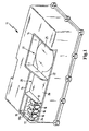
- FIG. 1 the lower shell 11 of a cylinder head cover is shown, on each of which a segment of different functional elements is formed.
- Three juxtaposed cups 16 form in the assembled state with a not shown Upper shell the functional element of the cyclone separator. The outside of the cup 16 has free connection to the cylinder head space 22.
- the end faces of the cup 16 through the upper shell 12 (FIG. FIG. 2 ), so that the crankcase gases can only be flowed over via the tangential recesses 17.
- the cups 16 constrict in a conical region up to a partition wall 19b of a directly adjacent reservoir 19 and communicate by a in FIG. 2 shown connection hole 18 with the reservoir 19.
- the functional element of the cyclone is sealed in the assembled state by the sealing contour 14, which communicates with the sealing contour of the upper shell, not shown, whereby the function of the cyclone is ensured.
- the sealing contour 14 rotates all the individual functional elements.
- the three adjacent cups 16 are connected by a connecting web 24 to the lower shell, but it is also possible to arrange the cups 16 directly adjacent to a wall of the lower shell 11.
- the upper side of the cup 16, to which the tangential recesses 17 are located and the top of the connecting web 24 thus form the upper parting plane of the tool.
- a pressure vessel 28 is formed in the assembled state, wherein the function of the pressure vessel 28 after assembly of the upper shell 12 (FIG. FIG. 2 ) is guaranteed.
- the pressure vessel 28 is sealed to the bottom or to the cylinder head space 22 by a molded-in bottom plate 26.
- Another segment of the functional element ⁇ lein Stahlllstutzen 27 is formed in the assembled state with the upper shell 12 ( FIG. 2 ). Also this segment is sealed in the assembled state by the sealing contour 14.
- the functional element ⁇ lein Stahlen 27 is limited by the shield plate 25.
- the shield plate 25 serves only as a splash guard for the oil in the cylinder head. A drainage of the oil must be ensured at the edges of the shield plate 25.
- FIG. 2 the functional element cyclone separator is visible, wherein both segments of the cyclone separator or the upper shell 12 and the lower shell 11 are sealingly connected to each other.
- the lower shell 11 is fastened to the cylinder head 23 by connecting elements, not shown.
- the upper shell 12 is sealingly connected both with the sealing contours 14 and with the end faces of the cup 16.
- the pressure control valve 13 is integrated in direct extension of the dip tube 15 in the upper shell 12 and has the task to keep the negative pressure in the cylinder head space 22 constant.
- the dip tube 15 opens in conical region of the cup 16.
- the tangential recess 17 is arranged in the illustrated embodiment on the top, but this may also be arranged laterally or on the bottom.
- the angle of inclination of the cups 16 must be selected so that there is a slight sloping inclination relative to the reservoir 19, even in the conical region.
- the reservoir 19 is arranged, which communicates through a connecting hole 18 through the partition wall 19 b with the cup 16.
- the reservoir 19 is sealed at the ends of its side walls as well by the peripheral sealing contour 14 sealing.
- a return hole 20 is arranged, which is closed in the operating state of the internal combustion engine by a return valve 21 and the stationary state of the internal combustion engine opens.
- the forming functional unit of the cyclone separator can be arranged individually or in parallel with a plurality of cyclone separators.
- a reservoir 19 is not mandatory, since a drainage of the separated liquid is also conceivable through the connection hole 18 directly into the cylinder head space 22.
- the crankcase gases are sucked in through an intake 13a, which communicates with the intake tract of the internal combustion engine.
- the crankcase gases flow out of the cylinder head space 22 through the tangential recess 17 into the cup 16 and are thereby guided in rotation about the dip tube 15, whereby the oil particles deposit on the walls of the cup 16 and follow the force of gravity and the flow direction through the connection hole 18 the reservoir 19 can drain.
- the pre-cleaned gases are passed through the pressure control valve 13 via the suction port 13a back to the intake.
- the separated liquid collects in the reservoir 19, wherein the return valve 21 closes the return 20 in the operating state and at partial load or during idling or standstill of the engine, the return valve opens the reservoir again.
- the return valve 21 When the return valve 21 is open, the separated oil flows off into the cylinder head space 22 and thus into the oil circuit.
Landscapes
- Engineering & Computer Science (AREA)
- Mechanical Engineering (AREA)
- General Engineering & Computer Science (AREA)
- Cylinder Crankcases Of Internal Combustion Engines (AREA)
- Lubrication Details And Ventilation Of Internal Combustion Engines (AREA)
Description
- Die Erfindung betrifft eine Zylinderkopfhaube, insbesondere zur Abdeckung des Zylinderkopfes einer Brennkraftmaschine, nach dem Oberbegriff des Patentanspruches 1.
- Zylinderkopfhauben haben die Aufgabe, den Raum des Zylinderkopfes zur Außenseite des Motors abzuschließen. Innerhalb des Zylinderkopfes sind, bedingt durch den Betrieb der Brennkraftmaschine, überwiegend Blow-by-Gase aus dem Verbrennungsprozess sowie Öltröpfchen aus dem Schmierkreislauf der Brennkraftmaschine vorhanden. Diese im Zylinderkopfraum vorhandenen Gas- und Flüssigkeitsmengen werden üblicherweise über Abscheidevorrichtungen geführt und dem Ansaugbereich bzw. dem Ölkreislauf wieder zugeleitet. Solche Abscheidevorrichtungen zum Trennen der Ölanteile des Kurbelgehäusegases werden üblicherweise in unmittelbarer Nähe der Zylinderkopfhaube oder idealerweise in der Zylinderkopfhaube integriert eingebracht.
- Die
DE10235983 zeigt eine an eine Zylinderkopfhaube angeformte Luft-Öl-Abscheidevorrichtung. Die Abscheidevorrichtung besteht aus einem Zentrifugal-Ölnebelabscheider mit einer Trennkammer, die eine Ölabscheideplatte 41 in eine stromaufwärtig liegende Trennkammer und eine stromabwärtige liegende Trennkammer unterteilt. In den Zentrifugalabscheider ist ein Ventil eingesetzt. Zur Ausbildung einer Ölauslasskammer ist eine Bodenplatte als zusätzliches Bauteil in die Zylinderkopfhaube eingesetzt. - In der
JP 2002 235520 A - In der
DE 101 27 819 wird eine Zylinderkopfhaube gezeigt, an welcher eine Vorabscheideeinrichtung, eine Zyklonabscheideeinrichtung, eine Feinabscheideeinrichtung und eine Ventileinrichtung kaskadenförmig angeordnet sind. Die erwähnten Funktionselemente sind einzeln und in unmittelbarer Nähe nebeneinander auf der Unterschale der Zylinderkopfhaube angeordnet. Alle Funktionselemente werden von einer Gehäusehalbschale überdeckt. Die Gehäusehalbschale dient nur zum dichtenden Abschließen gegenüber der Umgebungsseite und weist weiterhin keine Funktion zum Abscheideprozess auf. Nachteilig hierbei ist, dass für die Fertigung der einzelnen Funktionselemente ein hoher konstruktiver und fertigungstechnischer Aufwand benötigt wird und ein hoher Materialbedarf besteht. - Die Aufgabe der Erfindung besteht darin, die oben stehenden Nachteile zu vermeiden und eine Zylinderkopfhaube zu schaffen, an welcher Funktionselemente, insbesondere Abscheidevorrichtungen, vorzugsweise Ölabscheidevorrichtungen integriert werden können. Diese Zylinderkopfhaube soll fertigungstechnisch einfach und wirtschaftlich herstellbar sein.
- Diese Aufgabe wird durch die Merkmale des Patentanspruches 1 gelöst.
- Die erfindungsgemäße Zylinderkopfhaube eignet sich insbesondere zur Abdeckung eines Zylinderkopfes einer Brennkraftmaschine und zur Integration von Ölabscheidevorrichtungen in die Zylinderkopfhaube.
- Die Zylinderkopfhaube besteht aus einer Unterschale, an welcher auf der Unterseite ein umschließender Dichtflansch angeordnet ist, über welchen die Zylinderkopfhaube mit dem Zylinderkopf verbunden ist. Die nach oben gewölbte Unterschale umschließt den gesamten Zylinderkopf haubenförmig. Weiterhin sind in der Unterschale Funktionskonturen angebracht, welche jeweils ein Segment für ein Funktionselement bilden. Als jeweil i-ge Funktionselemente sind insbesondere Ölabscheidevorrichtungen vorgesehen. Die an der Unterschale vorhandenen Funktionskonturen werden wiederum von einer Dichtungskontur umschlossen. Ein Segment bildet eine Funktionskontur für einen Zyklonabscheider, wobei dieses Segment einen Becher eines Zyklons darstellt. Dieser Becher ist derart in die Unterschale integriert, dass ein unterer Wandungsabschluss des Bechers in den Zylinderkopfraum ragt und ein oberer Wandungsabschluss des Bechers in die Oberseite der Unterschale hineinragt. An der Becherwandung ist auf einer geöffn eten Seite eine tangentiale Aussparung angebracht. Der Becher verjüngt sich auf einer unteren Seite durch einen Konus bis auf ein kleines Verbindungsloch, das einen Verbindungsquerschnitt zum Zylinderkopfraum herstellt. An der Unterschale der Zylinderkopfhaube ist somit der Becher des Zyklons als ein Segment integriert. Eine Oberschale der Zylinderkopfhaube überdeckt die Funktionskontur der Unterschale und dichtet diese mit kommunizierenden Dichtungskonturen ab. Weiterhin ist in der Oberschale ein die Oberschale durchdringendes Tauchrohr angeordnet, welches in seiner Position konzentrisch zum Becher positioniert ist. Das Tauchrohr ragt in montiertem Zustand bis in den konischen Bereich des Bechers hinein. Dabei durchdringt das Tauchrohr eine Wandung der Oberschale und bildet auf der Außenseite einen geeigneten Anschluss zur Verbindung mit einem Volumenstrom. Dieser Volumenstrom wird üblicherweise durch den am Ansaugrohr vorhandenen Differenzdruck erreicht. Um den Einbauraum im Zylinderkopf optimal auszunutzen, können auch mehrere Zyklonen nebeneinander angeordnet werden, welche dann parallel oder in Reihe geschaltet sind oder durch vorgesehene Aktuatoren dem Volumenstrom angepasst optional zu- oder abgeschaltet werden. Die mit Öldampf belasteten Gase aus dem Raum des Zylinderkopfes werden durch eine tangentiale Aussparung an der Oberseite des Bechers angesaugt und durch die Becherform in eine rotierende, spiralförmige Bewegung geleitet. Von der Mündungsseite des Tauchrohrs werden sie durch die Oberschale abgesaugt und in der Regel wieder dem Ansaugtrakt des Verbrennungsmotors zugeführt. Die im Gas vorhandenen Ölpartikel werden durch die Rotation um das Tauchrohr an die Wandung des Bechers geschleudert und fließen der Schwerkraft folgend durch das Verbindungsloch in den Zylinderkopfraum ab. Der Zyklonabscheider kann auch mit weiteren Fein- oder Grobabscheidern kombiniert werden, welche ebenso integral in die Zylinderkopfhaube integriert sein können, wie z. B. ein Labyrinthabscheider.
- Die erfindungsgemäße Zylinderkopfhaube erlaubt es, in vorteilhafter Weise die Anzahl zusätzlicher Bauteile zu reduzieren. Einzelteile, die sonst separat gefertigt und gefügt werden müssen, sind bereits in die Ober- bzw. Unterschale integriert und erfüllen ihre Funktion nach der Montage. Die Einzelteile können mit der jeweiligen Schale auch verclipst, verklebt oder verschweißt werden. Vorzugsweise sind die Schalen einstückig hergestellt. Zusätzlich erforderliche Funktionselemente, wie z. B. Federn, Membrane, Ventile oder Verschlusselemente, kö nnen bereits vor dem Fügevorgang der Schalen montiert werden. Durch die Integration der Funktionssegmente ergibt sich auch ein konstruktiver Freiraum, durch welchen der notwendige Raumbedarf verringert werden kann.
- Eine vorteilhafte Ausgestaltung der Erfindung ergibt sich durch die Materialwahl von Kunststoffspritzguss für beide Schalenteile, wobei die Teilungsebene der Werkzeuge in den Bereich des Zyklons gelegt werden kann, wodurch sich eine hinterschnittsfreie Konstruktion des Werkzeuges ermöglicht. Der zusätzliche Werkzeugaufwand kann bei dieser Gestaltung auf jeweils einen Seitenschieber minimiert werden, welcher an der Oberschale das Mittelrohr und an der Unterschale die Becherform des Zyklon bildet. Neben der variablen Gestaltungsmöglichkeit, die sich durch die Auswahl des Kunststoffspritzgusses ergibt, ist mit diesem Kunststoffmaterial auch ein angestrebter Gewichtsvorteil zu erreichen.
- Eine weitere vorteilhafte Ausgestaltung der Erfindung ergibt sich bei Verwendung von Kunststoffmaterial dahingehend, dass die beiden Schalen über korrespondierende Dichtflächen miteinander verschweißt werden. Neben einer Kleb-, Schraub- oder Rastverbindung ergibt sich durch eine Schweißverbindung die Möglichkeit, auf zusätzliche Verbindungsteile zu verzichten und eine dauerhaft dichte und zuverlässige Verbindung herzustellen. Auf zusätzliche Elemente, wie Dichtungen und Verbindungselemente kann beim Schweißverfahren verzichtet werden, wodurch sich auch ein Raumvorteil im Verbindungsbereich ergibt.
- Die erfindungsgemäße Ausgestaltung des Erfindungsgedankens ergibt sich durch die Einformung eines Reservoirs in der Unterschale, wobei das Reservoir durch die Oberschale dichtend verschlossen werden kann und ein weiteres Funktionsteil darstellt. Dieses Reservoir kann z. B. die Funktion eines Ausgleichsbehälters wahrnehmen, welcher beispielsweise für die Funktion eines unterdruckgesteuerten Aktuators erforderlich ist. In diesem Fall ist das Reservoir über einen Anschlussstutzen durch einen Strömungsquerschnitt mit einem Leitungssystem verbunden. Vorteilhaft hierbei ist, dass das angeordnete Reservoir eine Zusatzfunktion bildet, welche unabhängig von der Funktion der Zylinderkopfhaube genutzt werden kann. Durch die räumliche Integrierung des Reservoirs in die Zylinderkopfhaube kann der zur Verfügung stehende Raum genutzt werden, und es wird an anderer Stelle ein Einbauraum eingespart.
- Die erfindungsgemäße Ausführungsform der Erfindung ergibt sich durch die Anordnung eines Reservoirs, welches durch ein Verbindungsloch mit einer Zykloneinheit kommuniziert. Der Boden dieses Reservoirs ist geodätisch tiefer angeordnet als das Verbindungsloch zum Zyklonabscheider. Idealerweise ist an einem Tiefpunkt des Reservoirs ein Rücklaufventil angeordnet, welches das Reservoir durch den im Betriebszustand des Motors entstehenden Unterdruck nach oben hin verschließt. Bei dieser Anordnung sammelt sich während des Betriebszustandes des Motors das abgeschiedene Öl, welches durch das Verbindungsloch in das Reservoir fließt, im Reservoir an und wird bei abgestelltem Motor durch das Öffnen des Rücklaufventils in den Zylinderkopfraum abfließen. Durch das Verschließen des Reservoirs im Betriebszustand des Motors wird ein Ablaufen des Öls durch das Verbindungsloch im Zyklonraum ausgeschlossen. Somit wird das gesamte Abscheidegas, welches durch den Zyklon strömt, durch die tangentiale Aussparung angesaugt, wodurch sich der Wirkungsgrad des Zyklons erhöht. Auf diese Weise werden vorteilhaft auch die Funktionsteile, welche den Ölabfluss des abgeschiedenen Öls regeln, in die Zylinderkopfhaube integriert.
- Es ist weiterhin vorteilhaft, ein Druckregelventil in Verbindung mit dem Zyklonabscheider anzubringen. Hierbei bietet es sich an, den Grundkörper des Druckregelventils in direkter Verlängerung zum Tauchrohr des Zyklons anzuordnen und die übrigen Funktionselemente des Druckregelventils, wie beispielsweise Federn, Membranen, Verschlussventil und Deckel, separat an das Druckregelventil zu montieren. Eine Möglichkeit, das Druckregelventil mit dem Tauchrohr zu verbinden, wird auch durch eine Steckverbindung ermöglicht, wobei in dieser Ausführungsform an der Oberschale oder am Körper des Druckregelventils eine Muffe vorhanden sein muss. Die ölbehafteten Verbrennungsgase aus dem Zylinderkopfraum werden somit durch den Becher des Zyklonabscheiders tangential angeströmt, in Rotation gebracht und rotieren weiter spiralförmig zur unteren Seite des Tauchrohres, von welchem sie angesaugt werden. Im weiteren Verlauf strömen die vorgereinigten Gase durch das Druckregelventil über den Saugstutzen zurück zum Ansaugtrakt des Verbrennungsmotors. Vorteilhaft bei einer direkten Verbindung zwischen dem Gehäuse des Druckregelventils und der Oberschale ist die weitere Integration von Funktionselementen in ein einzelnes Bauteil, wodurch die Handhabung und Logistik im Bereich der Fertigung und Montage verringert werden kann. Weiterhin kann auf Befestigung und Verbindungsteile zwischen Druckregelventil und Zylinderkopfhaube verzichtet werden. Die direkte Querschnittsverlängerung, welche vom Tauchrohr in das Druckregelventil übergeht, verringert mögliche Strömungswiderstände, wodurch sich das Tauchrohr relativ schlank gestalten lässt.
- Diese und weitere Merkmale von bevorzugten Weiterbildungen der Erfindung gehen außer aus den Ansprüchen auch aus der Beschreibung und der Zeichnung hervor, wobei die einzelnen Merkmale jeweils für sich allein oder zu mehreren in Form von Unterkombinationen bei der Ausführungsform der Erfindung und auf anderen Gebieten verwirklicht sein und vorteilhafte sowie für sich schutzfähige Ausführungen darstellen können, für die hier Schutz beansprucht wird.
- Ein Ausführungsbeispiel der Erfindung wird nachfolgend anhand der Zeichnung erläutert. Hierbei zeigt
- Figur 1
- die Unterschale einer Zylinderkopfhaube in perspektivischer Ansicht und
- Figur 2
- den Vollschnitt durch eine komplettierte Zylinderkopfhaube in Höhe eines mit dem Druckregelventil kombinierten Zyklons. Der
Figur 1 entsprechende Bauteile sind mit den gleichen Bezugszeichen versehen. - In
Figur 1 ist die Unterschale 11 einer Zylinderkopfhaube dargestellt, an welcher jeweils ein Segment verschiedener Funktionselemente eingeformt ist. Drei nebeneinander angeordnete Becher 16 bilden in zusammengebautem Zustand mit einer nicht dargestellten Oberschale das Funktionselement des Zyklonabscheiders. Die Außenseite der Becher 16 hat freie Verbindung zum Zylinderkopfraum 22. In montiertem Zustand sind die Stirnseiten der Becher 16 durch die Oberschale 12 (Figur 2 ) verschlossen, so dass die Kurbelgehäusegase nur über die tangentialen Aussparungen 17 angeströmt werden können. Die Becher 16 verengen sich in einem konischen Bereich bis zu einer Trennwand 19b eines direkt angrenzenden Reservoirs 19 und kommunizieren durch ein inFigur 2 dargestelltes Verbindungsloch 18 mit dem Reservoir 19. Das Funktionselement des Zyklons ist in montiertem Zustand durch die Dichtungskontur 14, welche mit der Dichtungskontur der nicht dargestellten Oberschale kommuniziert, dichtend verschlossen, wodurch die Funktion des Zyklons gewährleistet wird. Im dargestellten Ausführungsbeispiel umläuft die Dichtungskontur 14 alle einzelnen Funktionselemente. Es ist jedoch auch möglich, die einzelnen Funktionselemente räumlich voneinander zu trennen und mit mehreren Oberschalen abzuschließen. Die drei nebeneinander angeordneten Becher 16 sind durch einen Verbindungssteg 24 mit der Unterschale verbunden, es ist jedoch auch möglich, die Becher 16 direkt angrenzend an eine Wand der Unterschale 11 anzuordnen. Die obere Seite der Becher 16, an welchen sich auch die tangentialen Aussparungen 17 befinden und die Oberseite des Verbindungssteges 24 bilden somit die obere Teilungsebene des Werkzeuges. Als weiteres Funktionselement bildet sich in montiertem Zustand ein Druckbehälter 28, wobei die Funktion des Druckbehälters 28 nach der Montage der Oberschale 12 (Figur 2 ) gewährleistet ist. Der Druckbehälter 28 ist zur Unterseite bzw. zum Zylinderkopfraum 22 durch eine eingeformte Bodenplatte 26 dichtend abgeschlossen. Ein weiteres Segment des Funktionselementes Öleinfüllstutzen 27 bildet sich in montiertem Zustand mit der Oberschale 12 (Figur 2 ). Auch dieses Segment wird in montiertem Zustand durch die Dichtungskontur 14 dichtend abgeschlossen. Zur unteren Seite des Zylinderkopfraums 22 hin wird das Funktionselement Öleinfüllstutzen 27 durch die Abschirmplatte 25 begrenzt. Die Abschirmplatte 25 dient nur als Spritzschutz für das Öl im Zylinderkopf. Ein Abfließen des Öls muss an den Rändern der Abschirmplatte 25 gewährleistet sein. - In
Figur 2 ist das Funktionselement Zyklonabscheider sichtbar, wobei beide Segmente des Zyklonabscheiders bzw. die Oberschale 12 und die Unterschale 11 miteinander dichtend verbunden sind. In der ausschnittsweise dargestellten Zylinderkopfhaube 10 ist die Unterschale 11 durch nicht dargestellte Verbindungselemente an dem Zylinderkopf 23 befestigt. Die Oberschale 12 ist sowohl mit den Dichtungskonturen 14 als auch mit den Stirnseiten des Bechers 16 dichtend verbunden. Das Druckregelventil 13 ist in direkter Verlängerung des Tauchrohres 15 in die Oberschale 12 integriert und hat die Aufgabe den Unterdruck im Zylinderkopfraum 22 konstant zu halten. Das Tauchrohr 15 mündet im konischen Bereich des Bechers 16. Die tangentiale Aussparung 17 ist im abgebildeten Ausführungsbeispiel auf der Oberseite angeordnet, diese kann jedoch ebenso seitlich oder auf der Unterseite angeordnet sein. Der Neigungswinkel der Becher 16 muss so ausgewählt werden, dass gegenüber dem Reservoir 19 auch im konischen Bereich eine geringe abschüssige Neigung besteht. Direkt angrenzend zum Becher 16 ist das Reservoir 19 angeordnet, welches durch ein Verbindungsloch 18 durch die Trennwand 19b mit dem Becher 16 kommuniziert. Das Reservoir 19 wird an den Stirnseiten seiner Seitenwände ebenso durch die umlaufende Dichtungskontur 14 dichtend abgeschlossen. Im tiefsten Punkt des Reservoirs 19 ist ein Rücklaufloch 20 angeordnet, welches im Betriebszustand der Brennkraftmaschine durch ein Rücklaufventil 21 verschlossen ist und sich beim Still stand der Brennkraftmaschine öffnet. Die sich bildende Funktionseinheit des Zyklonabscheiders kann einzeln oder auch parallel mit mehreren Zyklonabscheidern angeordnet sein. Auch ist die Anordnung eines Reservoirs 19 nicht zwingend notwendig, da ein Abfließen der abgeschiedenen Flüssigkeit auch durch das Verbindungsloch 18 direkt in den Zylinderkopfraum 22 denkbar ist. Im Betriebszustand der Brennkraftmaschine werden die Kurbelgehäusegase durch einen Saugstutzen 13a, welcher mit dem Ansaugtrakt der Brennkraftmaschine in Verbindung steht, angesaugt. Dadurch strömen die Kurbelgehäusegase aus dem Zylinderkopfraum 22 durch die tangentiale Aussparung 17 in den Becher 16 und werden dadurch rotierend um das Tauchrohr 15 geleitet, wodurch sich die Ölpartikel an den Wandungen des Bechers 16 ablagern und der Schwerkraft und der Strömungsrichtung folgend durch das Verbindungsloch 18 in das Reservoir 19 abfließen können. Die vorgereinigten Gase werden durch das Druckregelventil 13 über den Saugstutzen 13a wieder zum Ansaugtrakt geführt. Die abgeschiedene Flüssigkeit sammelt sich im Reservoir 19, wobei das Rücklaufventil 21 den Rücklauf 20 im Betriebszustand verschließt und bei Teillast bzw. im Leerlauf oder Stillstand des Motors das Rücklaufventil das Reservoir wieder öffnet. Bei geöffnetem Rücklaufventil 21 fließt das abgeschiedene Öl in den Zylinderkopfraum 22 ab und damit in den Ölkreislauf ab.
Claims (6)
- Zylinderkopfhaube (10), insbesondere zur Abdeckung eines Zylinderkopfes (23) einer Brennkraftmaschine, aufweisend mehrere Funktionselemente, wie einen Öleinfüllstutzen (27) und wenigstens eine Ölabscheidevorrichtung, wobei die Kontur der Zylinderkopfhaube (10) durch eine Unterschale (11) und eine Oberschale (12) gebildet ist, wobei die Funktionselemente jeweils aus zwei Segmenten gebildet sind, wobei jeweils ein Segment integral an der unteren Schale (12) und das zweite Segment integral an der oberen Schale (12) angeordnet ist und die jeweiligen Segmente durch kommunizierende Dichtungskonturen (14) verbunden sind, wobei wesentliche Funktionsteile der Ölabscheidevorrichtung an der Unterschale und an der Oberschale (12) angeordnet sind, dergestalt, dass als Ölabscheidevorrichtung wenigstens ein Zyklon vorgesehen ist, welcher einen Becher (16) und ein Tauchrohr (15) aufweist, wobei der Becher (16) an der Unterschale (11) und das Tauchrohr (15) an der Oberschale (12) angeordnet ist, dadurch gekennzeichnet, dass durch ein Funktionselement ein Reservoir (19) gebildet ist, welches durch ein Verbindungsloch (18) mit einer Zykloneinheit kommuniziert, wobei der Boden des Reservoir (19) geodätisch tiefer angeordnet ist als das Verbindungsloch (18) zum Zyklonabscheider.
- Zylinderkopfhaube nach Anspruch 1, dadurch gekennzeichnet, dass beide Schalen (11, 12) der Zylinderkopfhaube (10) aus Kunststoffspritzguss hergestellt sind.
- Zylinderkopfhaube nach einem der vorhergehenden Ansprüche, dadurch gekennzeichnet, dass die Oberschale (12) und die Unterschale (11) durch ein Schweißverfahren dicht miteinander verbunden sind, derart, dass durch die Verbindung die Funktion der Funktionselemente gewährleistet ist.
- Zylinderkopfhaube nach einem der vorhergehenden Ansprüche, dadurch gekennzeichnet, dass das Reservoir (19) durch ein Verbindungsloch mit einem Ölablauf des Zyklons verbunden ist, wobei am tiefsten Punkt des Reservoirs (19) ein Ventil angeordnet ist, welches das Reservoir (19) im Betriebszustand der Brennkraftmaschine verschließt.
- Zylinderkopfhaube nach einem der vorhergehenden Ansprüche, dadurch gekennzeichnet, dass durch ein Funktionselement ein Unterdruckbehälter (28) gebildet ist.
- Zylinderkopfhaube nach einem der vorhergehenden Ansprüche, dadurch gekennzeichnet, dass die Oberschale (12) und/oder die Unterschale (11) mit einem Druckregelventil (13) verbunden ist.
Applications Claiming Priority (2)
| Application Number | Priority Date | Filing Date | Title |
|---|---|---|---|
| DE102004004753A DE102004004753A1 (de) | 2004-01-30 | 2004-01-30 | Zylinderkopfhaube |
| DE102004004753 | 2004-01-30 |
Publications (3)
| Publication Number | Publication Date |
|---|---|
| EP1559876A2 EP1559876A2 (de) | 2005-08-03 |
| EP1559876A3 EP1559876A3 (de) | 2009-12-02 |
| EP1559876B1 true EP1559876B1 (de) | 2011-05-18 |
Family
ID=34638811
Family Applications (1)
| Application Number | Title | Priority Date | Filing Date |
|---|---|---|---|
| EP05100459A Expired - Lifetime EP1559876B1 (de) | 2004-01-30 | 2005-01-25 | Zylinderkopfhaube |
Country Status (5)
| Country | Link |
|---|---|
| US (1) | US7137372B2 (de) |
| EP (1) | EP1559876B1 (de) |
| JP (1) | JP4624119B2 (de) |
| AT (1) | ATE510112T1 (de) |
| DE (1) | DE102004004753A1 (de) |
Families Citing this family (23)
| Publication number | Priority date | Publication date | Assignee | Title |
|---|---|---|---|---|
| DE102005006438A1 (de) * | 2005-02-12 | 2006-08-17 | Dr.Ing.H.C. F. Porsche Ag | Einrichtung zur Entlüftung eines Kurbelgehäuses einer Brennkraftmaschine sowie Brennkraftmaschine mit insbesondere V-förmiger Anordnung der Zylinder |
| DE202005010449U1 (de) * | 2005-06-30 | 2006-11-09 | Mann + Hummel Gmbh | Zylinderkopfhaube für einen Zylinderkopf einer Brennkraftmaschine |
| DE202005013112U1 (de) * | 2005-08-17 | 2006-12-28 | Hengst Gmbh & Co.Kg | Ölabscheider zur Abscheidung von Öl aus dem Kurbelgehäuseentlüftungsgas einer Brennkraftmaschine |
| JP4506656B2 (ja) * | 2005-11-25 | 2010-07-21 | トヨタ紡織株式会社 | オイルミストセパレータ及びシリンダヘッドカバー |
| JP4534977B2 (ja) * | 2005-12-09 | 2010-09-01 | トヨタ紡織株式会社 | シリンダヘッドカバー |
| DE102005061477B4 (de) * | 2005-12-22 | 2010-04-08 | Audi Ag | Vorrichtung zur Ölabscheidung |
| DE102005063274B9 (de) * | 2005-12-28 | 2013-05-08 | Elringklinger Ag | Ölabscheider |
| DE102006019880A1 (de) * | 2006-04-28 | 2007-10-31 | Audi Ag | Motorgehäusedeckel eines Verbrennungsmotors mit Entlüftungssystem |
| DE102007058059B4 (de) * | 2007-01-26 | 2015-06-11 | Dichtungstechnik G. Bruss Gmbh & Co. Kg | Ölabscheideranordnung sowie Zylinderkopfhaube für einen Verbrennungsmotor |
| EP1961928B1 (de) * | 2007-02-23 | 2018-07-25 | Dr. Ing. h.c. F. Porsche AG | Ölvorabscheider für Kurbelgehäusegas |
| DE202007011585U1 (de) | 2007-08-17 | 2007-10-18 | Dichtungstechnik G. Bruss Gmbh & Co. Kg | Ölrücklaufventil für Kurbelgehäuseentlüftung |
| JP4510108B2 (ja) * | 2008-03-13 | 2010-07-21 | 小島プレス工業株式会社 | ブローバイガス用オイルセパレータ |
| DE102009011983A1 (de) | 2009-03-05 | 2010-09-09 | Schaeffler Technologies Gmbh & Co. Kg | Hydraulikeinheit für einen Zylinderkopf einer Brennkraftmaschine mit hydraulisch variablem Gaswechselventiltrieb |
| DE102011106593B4 (de) | 2010-07-06 | 2022-01-13 | BRUSS Sealing Systems GmbH | Gehäuse für einen Verbrennungsmotor und ein an dem Gehäuse befestigtes PCV-Ventil zur Kurbelgehäuseentlüftung, und Verfahren zum Befestigen eines PCV-Ventils an einem Gehäuse |
| DE102011079166A1 (de) | 2011-07-14 | 2013-01-17 | Mahle International Gmbh | Brennkraftmaschine |
| DE202012005909U1 (de) * | 2012-06-16 | 2013-06-17 | Reinz-Dichtungs-Gmbh | Abdecksystem |
| US9080478B2 (en) | 2013-01-21 | 2015-07-14 | Ford Global Technologies, Llc | Oil separator |
| DE102013212104B4 (de) | 2013-06-25 | 2021-06-10 | BRUSS Sealing Systems GmbH | Zylinderkopfhaube mit Rückschlagventil für einen Ölrücklauf in der Kurbelgehäuseentlüftung eines Verbrennungsmotors |
| US10247068B2 (en) | 2013-06-25 | 2019-04-02 | BRUSS Sealing Systems GmbH | Oil separating module in the crankcase ventilation system of a combustion engine |
| DE102014109075A1 (de) * | 2014-06-27 | 2015-12-31 | Elringklinger Ag | Zylinderkopfhaube und Verfahren zur Herstellung einer Zylinderkopfhaube |
| DE102017201896B4 (de) | 2017-02-07 | 2022-10-20 | Mahle International Gmbh | Verfahren zum Entlüften eines Kurbelgehäuses einer Brennkraftmaschine und zugehörige Einrichtung |
| JP6812396B2 (ja) * | 2018-04-17 | 2021-01-13 | トヨタ紡織株式会社 | Pcvバルブの取付構造 |
| JP7439710B2 (ja) * | 2020-09-17 | 2024-02-28 | トヨタ紡織株式会社 | オイルミストセパレータ |
Family Cites Families (21)
| Publication number | Priority date | Publication date | Assignee | Title |
|---|---|---|---|---|
| FR1035878A (fr) * | 1951-04-18 | 1953-09-01 | Couvre-culasse pour moteurs à culbuteurs | |
| DE3152747C2 (de) * | 1981-07-18 | 1984-01-26 | Bayerische Motoren Werke Ag, 8000 Muenchen | Zyklonölabscheider |
| JPS6030310U (ja) * | 1983-08-03 | 1985-03-01 | アイシン精機株式会社 | オイルセパレ−タ |
| DE3625836A1 (de) * | 1986-07-30 | 1988-02-11 | Audi Ag | Vorrichtung zur entlueftung des kurbelraumes einer brennkraftmaschine |
| DE4118557C2 (de) * | 1991-06-06 | 1993-10-14 | Daimler Benz Ag | Kurbelgehäuseentlüftung für eine Brennkraftmaschine |
| US5285754A (en) * | 1993-07-12 | 1994-02-15 | Freudenberg-Nok General Partnership | Valve cover assembly for internal combustion engines |
| JPH07180609A (ja) * | 1993-12-21 | 1995-07-18 | Nippon Mektron Ltd | エンジン用シリンダヘッドカバ−装置 |
| US5492086A (en) * | 1994-09-15 | 1996-02-20 | Durox Company, Inc. | Valve cover |
| DE19701977B4 (de) * | 1997-01-22 | 2006-11-23 | Iav Gmbh Ingenieurgesellschaft Auto Und Verkehr | Brennkraftmaschine mit einem Ventilkammerdeckel |
| DE19722948A1 (de) * | 1997-05-31 | 1999-02-11 | Bosch Gmbh Robert | Vorrichtung zum Anbau an einen Verbrennungsmotor |
| JP2000045750A (ja) * | 1998-07-24 | 2000-02-15 | Uchiyama Mfg Corp | ロッカカバーのオイルセパレータ |
| DE19913176A1 (de) * | 1999-03-24 | 2000-09-28 | Fev Motorentech Gmbh | Motorblock mit Ölabscheidung im Entlüftungsbereich |
| JP3899763B2 (ja) * | 2000-01-17 | 2007-03-28 | スズキ株式会社 | シリンダヘッドカバー構造 |
| DE60123350T2 (de) * | 2000-08-25 | 2007-05-10 | Daihatsu Motor Co., Ltd., Ikeda | Zylinderkopfdeckel für eine Brennmaschine |
| JP2002235520A (ja) * | 2001-02-09 | 2002-08-23 | Yanmar Diesel Engine Co Ltd | エンジンのブリーザ装置 |
| JP3967552B2 (ja) * | 2001-02-19 | 2007-08-29 | 本田技研工業株式会社 | エンジン用気液分離装置 |
| DE10127819A1 (de) * | 2001-06-07 | 2003-01-02 | Bosch Gmbh Robert | Ölabscheidevorrichtung für Kurbelgehäusegase einer Verbrennungskraftmaschine |
| JP3923288B2 (ja) * | 2001-08-06 | 2007-05-30 | 本田技研工業株式会社 | エンジンの気液分離装置 |
| US6453892B1 (en) * | 2001-10-11 | 2002-09-24 | Dana Corporation | Constrained layer damped steel baffle |
| ITTO20020149A1 (it) * | 2002-02-21 | 2003-08-21 | C R F Societa Con Sortile Per | Motore pluricilindrico a combustione interna con dispositivo idraulico a controllo elettronico per l'azionamento variabile delle valvole, in |
| US6860010B2 (en) * | 2002-05-15 | 2005-03-01 | Dow Global Technologies, Inc. | Method of forming an automotive valve cover with integral positive crankcase ventilation |
-
2004
- 2004-01-30 DE DE102004004753A patent/DE102004004753A1/de not_active Withdrawn
-
2005
- 2005-01-25 AT AT05100459T patent/ATE510112T1/de active
- 2005-01-25 EP EP05100459A patent/EP1559876B1/de not_active Expired - Lifetime
- 2005-01-27 JP JP2005019115A patent/JP4624119B2/ja not_active Expired - Fee Related
- 2005-01-31 US US11/045,076 patent/US7137372B2/en not_active Expired - Fee Related
Also Published As
| Publication number | Publication date |
|---|---|
| US20050188937A1 (en) | 2005-09-01 |
| EP1559876A2 (de) | 2005-08-03 |
| JP4624119B2 (ja) | 2011-02-02 |
| JP2005233182A (ja) | 2005-09-02 |
| ATE510112T1 (de) | 2011-06-15 |
| DE102004004753A1 (de) | 2005-08-18 |
| EP1559876A3 (de) | 2009-12-02 |
| US7137372B2 (en) | 2006-11-21 |
Similar Documents
| Publication | Publication Date | Title |
|---|---|---|
| EP1559876A2 (de) | Zylinderkopfhaube | |
| EP1399649B1 (de) | Ölabscheidevorrichtung für kurbelgehäusegase einer verbrennungskraftmaschine | |
| EP1080298B2 (de) | Ölabscheider zur entölung von kurbelgehäuse-entlüftungsgasen einer brennkraftmaschine | |
| DE102005059014B4 (de) | Ölabscheider für einen Verbrennungsmotor | |
| WO2012159909A1 (de) | Zentrifugalabscheider zum abscheiden von ölnebel aus dem kurbelgehäuseentlüftungsgas einer brennkraftmaschine | |
| EP2069042B1 (de) | Vorrichtung zum abscheiden von partikeln aus einem gasstrom | |
| EP0690209A1 (de) | Kurbelgehäuseentlüftung für Brennkraftmaschinen | |
| EP1614871A2 (de) | Einrichtung für die Regelung des Drucks im Kurbelgehäuse einer Brennkraftmaschine und für die Ölnebelabscheidung aus dem Kurbelgehäuseentlüftungsgas | |
| EP2220348A2 (de) | Ölnebelabscheider | |
| DE112008003587T5 (de) | Abscheider mit Transferrohrdrainage | |
| DE10127820A1 (de) | Ölabscheidevorrichtung für Kurbelgehäusegase einer Verbrennungskraftmaschine | |
| EP1402156B1 (de) | Ölabscheidevorrichtung für kurbelgehäusegase einer verbrennungskraftmaschine | |
| EP0730086B1 (de) | Zyklonabscheider für die Kurbelgehäuse-Entlüftung eines Verbrennungsmotors mit einem Entlüftungsventil | |
| DE19701977A1 (de) | Brennkraftmaschine mit einem Ventilkammerdeckel | |
| EP3067102B1 (de) | Wasserabscheider und wasserabscheidesystem mit integrierter wasseraustragseinrichtung | |
| DE102005063274B4 (de) | Ölabscheider | |
| DE19621935A1 (de) | Entlüftungssystem für Kurbelgehäuse, insbesondere von Brennkraftmaschinen | |
| EP1310637A2 (de) | Brennkraftmaschine mit mindestens zwei Zylinderbankreihen | |
| DE202007003292U1 (de) | Ölabscheider mit mindestens einem Zyklon | |
| EP1945922B1 (de) | Vorrichtung zum entlüften des kurbelgehäuses einer brennkraftmaschine und zum entölen des kurbelgehäuseentlüftungsgases | |
| DE102010002790B4 (de) | An eine Brennkraftmaschine anflanschbarer Ölnebelabscheider | |
| DE202018103711U1 (de) | Abscheider | |
| DE20302220U1 (de) | Ölabscheider zur Entölung von Kurbelgehäuseentlüftungsgasen einer Brennkraftmaschine | |
| DE102007005399A1 (de) | Saugfilter für Öl eines Getriebes und/oder eines Motors | |
| WO2014079591A1 (de) | Ölwannen-filterkombination, ölwanne und ablassvorrichtung einer ölwannen-filterkombination |
Legal Events
| Date | Code | Title | Description |
|---|---|---|---|
| PUAI | Public reference made under article 153(3) epc to a published international application that has entered the european phase |
Free format text: ORIGINAL CODE: 0009012 |
|
| AK | Designated contracting states |
Kind code of ref document: A2 Designated state(s): AT BE BG CH CY CZ DE DK EE ES FI FR GB GR HU IE IS IT LI LT LU MC NL PL PT RO SE SI SK TR |
|
| AX | Request for extension of the european patent |
Extension state: AL BA HR LV MK YU |
|
| RIN1 | Information on inventor provided before grant (corrected) |
Inventor name: HILPERT, TORSTEN Inventor name: WEBER, ANDREAS Inventor name: KORN, ALEXANDER |
|
| PUAL | Search report despatched |
Free format text: ORIGINAL CODE: 0009013 |
|
| AK | Designated contracting states |
Kind code of ref document: A3 Designated state(s): AT BE BG CH CY CZ DE DK EE ES FI FR GB GR HU IE IS IT LI LT LU MC NL PL PT RO SE SI SK TR |
|
| AX | Request for extension of the european patent |
Extension state: AL BA HR LV MK YU |
|
| 17P | Request for examination filed |
Effective date: 20100127 |
|
| 17Q | First examination report despatched |
Effective date: 20100614 |
|
| AKX | Designation fees paid |
Designated state(s): AT BE BG CH CY CZ DE DK EE ES FI FR GB GR HU IE IS IT LI LT LU MC NL PT RO SE SI SK TR |
|
| GRAP | Despatch of communication of intention to grant a patent |
Free format text: ORIGINAL CODE: EPIDOSNIGR1 |
|
| RIC1 | Information provided on ipc code assigned before grant |
Ipc: F01M 13/04 20060101AFI20101208BHEP |
|
| GRAS | Grant fee paid |
Free format text: ORIGINAL CODE: EPIDOSNIGR3 |
|
| GRAA | (expected) grant |
Free format text: ORIGINAL CODE: 0009210 |
|
| AK | Designated contracting states |
Kind code of ref document: B1 Designated state(s): AT BE BG CH CY CZ DE DK EE ES FI FR GB GR HU IE IS IT LI LT LU MC NL PT RO SE SI SK TR |
|
| REG | Reference to a national code |
Ref country code: GB Ref legal event code: FG4D Free format text: NOT ENGLISH |
|
| REG | Reference to a national code |
Ref country code: CH Ref legal event code: EP |
|
| REG | Reference to a national code |
Ref country code: IE Ref legal event code: FG4D Free format text: LANGUAGE OF EP DOCUMENT: GERMAN |
|
| REG | Reference to a national code |
Ref country code: DE Ref legal event code: R096 Ref document number: 502005011379 Country of ref document: DE Effective date: 20110630 |
|
| REG | Reference to a national code |
Ref country code: NL Ref legal event code: VDEP Effective date: 20110518 |
|
| PG25 | Lapsed in a contracting state [announced via postgrant information from national office to epo] |
Ref country code: SE Free format text: LAPSE BECAUSE OF FAILURE TO SUBMIT A TRANSLATION OF THE DESCRIPTION OR TO PAY THE FEE WITHIN THE PRESCRIBED TIME-LIMIT Effective date: 20110518 Ref country code: PT Free format text: LAPSE BECAUSE OF FAILURE TO SUBMIT A TRANSLATION OF THE DESCRIPTION OR TO PAY THE FEE WITHIN THE PRESCRIBED TIME-LIMIT Effective date: 20110919 Ref country code: LT Free format text: LAPSE BECAUSE OF FAILURE TO SUBMIT A TRANSLATION OF THE DESCRIPTION OR TO PAY THE FEE WITHIN THE PRESCRIBED TIME-LIMIT Effective date: 20110518 |
|
| PG25 | Lapsed in a contracting state [announced via postgrant information from national office to epo] |
Ref country code: IS Free format text: LAPSE BECAUSE OF FAILURE TO SUBMIT A TRANSLATION OF THE DESCRIPTION OR TO PAY THE FEE WITHIN THE PRESCRIBED TIME-LIMIT Effective date: 20110918 Ref country code: CY Free format text: LAPSE BECAUSE OF FAILURE TO SUBMIT A TRANSLATION OF THE DESCRIPTION OR TO PAY THE FEE WITHIN THE PRESCRIBED TIME-LIMIT Effective date: 20110518 Ref country code: ES Free format text: LAPSE BECAUSE OF FAILURE TO SUBMIT A TRANSLATION OF THE DESCRIPTION OR TO PAY THE FEE WITHIN THE PRESCRIBED TIME-LIMIT Effective date: 20110829 Ref country code: GR Free format text: LAPSE BECAUSE OF FAILURE TO SUBMIT A TRANSLATION OF THE DESCRIPTION OR TO PAY THE FEE WITHIN THE PRESCRIBED TIME-LIMIT Effective date: 20110819 Ref country code: FI Free format text: LAPSE BECAUSE OF FAILURE TO SUBMIT A TRANSLATION OF THE DESCRIPTION OR TO PAY THE FEE WITHIN THE PRESCRIBED TIME-LIMIT Effective date: 20110518 Ref country code: SI Free format text: LAPSE BECAUSE OF FAILURE TO SUBMIT A TRANSLATION OF THE DESCRIPTION OR TO PAY THE FEE WITHIN THE PRESCRIBED TIME-LIMIT Effective date: 20110518 |
|
| REG | Reference to a national code |
Ref country code: IE Ref legal event code: FD4D |
|
| PG25 | Lapsed in a contracting state [announced via postgrant information from national office to epo] |
Ref country code: NL Free format text: LAPSE BECAUSE OF FAILURE TO SUBMIT A TRANSLATION OF THE DESCRIPTION OR TO PAY THE FEE WITHIN THE PRESCRIBED TIME-LIMIT Effective date: 20110518 |
|
| PG25 | Lapsed in a contracting state [announced via postgrant information from national office to epo] |
Ref country code: IE Free format text: LAPSE BECAUSE OF FAILURE TO SUBMIT A TRANSLATION OF THE DESCRIPTION OR TO PAY THE FEE WITHIN THE PRESCRIBED TIME-LIMIT Effective date: 20110518 Ref country code: EE Free format text: LAPSE BECAUSE OF FAILURE TO SUBMIT A TRANSLATION OF THE DESCRIPTION OR TO PAY THE FEE WITHIN THE PRESCRIBED TIME-LIMIT Effective date: 20110518 Ref country code: CZ Free format text: LAPSE BECAUSE OF FAILURE TO SUBMIT A TRANSLATION OF THE DESCRIPTION OR TO PAY THE FEE WITHIN THE PRESCRIBED TIME-LIMIT Effective date: 20110518 |
|
| PG25 | Lapsed in a contracting state [announced via postgrant information from national office to epo] |
Ref country code: DK Free format text: LAPSE BECAUSE OF FAILURE TO SUBMIT A TRANSLATION OF THE DESCRIPTION OR TO PAY THE FEE WITHIN THE PRESCRIBED TIME-LIMIT Effective date: 20110518 Ref country code: SK Free format text: LAPSE BECAUSE OF FAILURE TO SUBMIT A TRANSLATION OF THE DESCRIPTION OR TO PAY THE FEE WITHIN THE PRESCRIBED TIME-LIMIT Effective date: 20110518 Ref country code: RO Free format text: LAPSE BECAUSE OF FAILURE TO SUBMIT A TRANSLATION OF THE DESCRIPTION OR TO PAY THE FEE WITHIN THE PRESCRIBED TIME-LIMIT Effective date: 20110518 |
|
| PLBE | No opposition filed within time limit |
Free format text: ORIGINAL CODE: 0009261 |
|
| STAA | Information on the status of an ep patent application or granted ep patent |
Free format text: STATUS: NO OPPOSITION FILED WITHIN TIME LIMIT |
|
| 26N | No opposition filed |
Effective date: 20120221 |
|
| PG25 | Lapsed in a contracting state [announced via postgrant information from national office to epo] |
Ref country code: IT Free format text: LAPSE BECAUSE OF FAILURE TO SUBMIT A TRANSLATION OF THE DESCRIPTION OR TO PAY THE FEE WITHIN THE PRESCRIBED TIME-LIMIT Effective date: 20110518 |
|
| REG | Reference to a national code |
Ref country code: DE Ref legal event code: R097 Ref document number: 502005011379 Country of ref document: DE Effective date: 20120221 |
|
| BERE | Be: lapsed |
Owner name: MANN+HUMMEL G.M.B.H. Effective date: 20120131 |
|
| PG25 | Lapsed in a contracting state [announced via postgrant information from national office to epo] |
Ref country code: MC Free format text: LAPSE BECAUSE OF NON-PAYMENT OF DUE FEES Effective date: 20120131 |
|
| REG | Reference to a national code |
Ref country code: CH Ref legal event code: PL |
|
| GBPC | Gb: european patent ceased through non-payment of renewal fee |
Effective date: 20120125 |
|
| REG | Reference to a national code |
Ref country code: FR Ref legal event code: ST Effective date: 20120928 |
|
| PG25 | Lapsed in a contracting state [announced via postgrant information from national office to epo] |
Ref country code: CH Free format text: LAPSE BECAUSE OF NON-PAYMENT OF DUE FEES Effective date: 20120131 Ref country code: LI Free format text: LAPSE BECAUSE OF NON-PAYMENT OF DUE FEES Effective date: 20120131 Ref country code: GB Free format text: LAPSE BECAUSE OF NON-PAYMENT OF DUE FEES Effective date: 20120125 |
|
| PG25 | Lapsed in a contracting state [announced via postgrant information from national office to epo] |
Ref country code: FR Free format text: LAPSE BECAUSE OF NON-PAYMENT OF DUE FEES Effective date: 20120131 Ref country code: BE Free format text: LAPSE BECAUSE OF NON-PAYMENT OF DUE FEES Effective date: 20120131 |
|
| REG | Reference to a national code |
Ref country code: AT Ref legal event code: MM01 Ref document number: 510112 Country of ref document: AT Kind code of ref document: T Effective date: 20120125 |
|
| PG25 | Lapsed in a contracting state [announced via postgrant information from national office to epo] |
Ref country code: AT Free format text: LAPSE BECAUSE OF NON-PAYMENT OF DUE FEES Effective date: 20120125 Ref country code: BG Free format text: LAPSE BECAUSE OF FAILURE TO SUBMIT A TRANSLATION OF THE DESCRIPTION OR TO PAY THE FEE WITHIN THE PRESCRIBED TIME-LIMIT Effective date: 20110818 |
|
| PG25 | Lapsed in a contracting state [announced via postgrant information from national office to epo] |
Ref country code: TR Free format text: LAPSE BECAUSE OF FAILURE TO SUBMIT A TRANSLATION OF THE DESCRIPTION OR TO PAY THE FEE WITHIN THE PRESCRIBED TIME-LIMIT Effective date: 20110518 |
|
| PG25 | Lapsed in a contracting state [announced via postgrant information from national office to epo] |
Ref country code: LU Free format text: LAPSE BECAUSE OF NON-PAYMENT OF DUE FEES Effective date: 20120125 |
|
| PG25 | Lapsed in a contracting state [announced via postgrant information from national office to epo] |
Ref country code: HU Free format text: LAPSE BECAUSE OF FAILURE TO SUBMIT A TRANSLATION OF THE DESCRIPTION OR TO PAY THE FEE WITHIN THE PRESCRIBED TIME-LIMIT Effective date: 20050125 |
|
| PGFP | Annual fee paid to national office [announced via postgrant information from national office to epo] |
Ref country code: DE Payment date: 20160120 Year of fee payment: 12 |
|
| REG | Reference to a national code |
Ref country code: DE Ref legal event code: R119 Ref document number: 502005011379 Country of ref document: DE |
|
| PG25 | Lapsed in a contracting state [announced via postgrant information from national office to epo] |
Ref country code: DE Free format text: LAPSE BECAUSE OF NON-PAYMENT OF DUE FEES Effective date: 20170801 |