EP1559489A2 - Gasdurchlässige Formen zum Giessen von Kompositmaterialien und Verfahren - Google Patents
Gasdurchlässige Formen zum Giessen von Kompositmaterialien und Verfahren Download PDFInfo
- Publication number
- EP1559489A2 EP1559489A2 EP04030091A EP04030091A EP1559489A2 EP 1559489 A2 EP1559489 A2 EP 1559489A2 EP 04030091 A EP04030091 A EP 04030091A EP 04030091 A EP04030091 A EP 04030091A EP 1559489 A2 EP1559489 A2 EP 1559489A2
- Authority
- EP
- European Patent Office
- Prior art keywords
- mold
- mold assembly
- gas
- permeable
- gaseous reactants
- Prior art date
- Legal status (The legal status is an assumption and is not a legal conclusion. Google has not performed a legal analysis and makes no representation as to the accuracy of the status listed.)
- Withdrawn
Links
- 238000000034 method Methods 0.000 title claims abstract description 56
- 238000000465 moulding Methods 0.000 title claims abstract description 56
- 239000002131 composite material Substances 0.000 title claims abstract description 34
- 238000004519 manufacturing process Methods 0.000 title abstract description 5
- 239000000376 reactant Substances 0.000 claims abstract description 50
- 239000000463 material Substances 0.000 claims abstract description 36
- 238000013022 venting Methods 0.000 claims abstract description 33
- 239000002783 friction material Substances 0.000 claims abstract description 18
- 229920001568 phenolic resin Polymers 0.000 claims abstract description 12
- 239000005011 phenolic resin Substances 0.000 claims abstract description 10
- 230000002787 reinforcement Effects 0.000 claims abstract description 5
- 239000004615 ingredient Substances 0.000 claims description 29
- WSFSSNUMVMOOMR-UHFFFAOYSA-N Formaldehyde Chemical compound O=C WSFSSNUMVMOOMR-UHFFFAOYSA-N 0.000 claims description 27
- 239000011148 porous material Substances 0.000 claims description 23
- 238000006243 chemical reaction Methods 0.000 claims description 21
- QGZKDVFQNNGYKY-UHFFFAOYSA-N Ammonia Chemical compound N QGZKDVFQNNGYKY-UHFFFAOYSA-N 0.000 claims description 18
- 229910021529 ammonia Inorganic materials 0.000 claims description 9
- 238000009833 condensation Methods 0.000 claims description 7
- 230000005494 condensation Effects 0.000 claims description 7
- 238000000354 decomposition reaction Methods 0.000 claims description 7
- 230000006798 recombination Effects 0.000 claims description 7
- 238000005215 recombination Methods 0.000 claims description 7
- 229910052782 aluminium Inorganic materials 0.000 claims description 6
- XAGFODPZIPBFFR-UHFFFAOYSA-N aluminium Chemical compound [Al] XAGFODPZIPBFFR-UHFFFAOYSA-N 0.000 claims description 6
- KXGFMDJXCMQABM-UHFFFAOYSA-N 2-methoxy-6-methylphenol Chemical compound [CH]OC1=CC=CC([CH])=C1O KXGFMDJXCMQABM-UHFFFAOYSA-N 0.000 claims description 4
- 238000010438 heat treatment Methods 0.000 claims description 3
- 239000007769 metal material Substances 0.000 claims 1
- 239000000047 product Substances 0.000 abstract description 18
- 239000007787 solid Substances 0.000 abstract description 6
- 229920001187 thermosetting polymer Polymers 0.000 abstract description 6
- 239000007789 gas Substances 0.000 abstract description 5
- 229920005989 resin Polymers 0.000 abstract description 5
- 239000011347 resin Substances 0.000 abstract description 5
- 239000006227 byproduct Substances 0.000 abstract description 4
- 239000011449 brick Substances 0.000 abstract description 3
- XEEYBQQBJWHFJM-UHFFFAOYSA-N Iron Chemical compound [Fe] XEEYBQQBJWHFJM-UHFFFAOYSA-N 0.000 description 6
- CPLXHLVBOLITMK-UHFFFAOYSA-N Magnesium oxide Chemical compound [Mg]=O CPLXHLVBOLITMK-UHFFFAOYSA-N 0.000 description 6
- 239000000835 fiber Substances 0.000 description 6
- 239000000203 mixture Substances 0.000 description 6
- -1 and the like) Substances 0.000 description 5
- TZCXTZWJZNENPQ-UHFFFAOYSA-L barium sulfate Chemical compound [Ba+2].[O-]S([O-])(=O)=O TZCXTZWJZNENPQ-UHFFFAOYSA-L 0.000 description 5
- 229920001971 elastomer Polymers 0.000 description 4
- OKTJSMMVPCPJKN-UHFFFAOYSA-N Carbon Chemical compound [C] OKTJSMMVPCPJKN-UHFFFAOYSA-N 0.000 description 3
- UQSXHKLRYXJYBZ-UHFFFAOYSA-N Iron oxide Chemical compound [Fe]=O UQSXHKLRYXJYBZ-UHFFFAOYSA-N 0.000 description 3
- 230000015572 biosynthetic process Effects 0.000 description 3
- 239000010439 graphite Substances 0.000 description 3
- 229910002804 graphite Inorganic materials 0.000 description 3
- 229910052742 iron Inorganic materials 0.000 description 3
- 239000000395 magnesium oxide Substances 0.000 description 3
- 239000000843 powder Substances 0.000 description 3
- 244000226021 Anacardium occidentale Species 0.000 description 2
- VYPSYNLAJGMNEJ-UHFFFAOYSA-N Silicium dioxide Chemical compound O=[Si]=O VYPSYNLAJGMNEJ-UHFFFAOYSA-N 0.000 description 2
- 229910000831 Steel Inorganic materials 0.000 description 2
- HCHKCACWOHOZIP-UHFFFAOYSA-N Zinc Chemical compound [Zn] HCHKCACWOHOZIP-UHFFFAOYSA-N 0.000 description 2
- 235000020226 cashew nut Nutrition 0.000 description 2
- 239000000571 coke Substances 0.000 description 2
- 238000000748 compression moulding Methods 0.000 description 2
- 239000000428 dust Substances 0.000 description 2
- VKYKSIONXSXAKP-UHFFFAOYSA-N hexamethylenetetramine Chemical compound C1N(C2)CN3CN1CN2C3 VKYKSIONXSXAKP-UHFFFAOYSA-N 0.000 description 2
- 235000013980 iron oxide Nutrition 0.000 description 2
- 229910052751 metal Inorganic materials 0.000 description 2
- 239000002184 metal Substances 0.000 description 2
- 239000010445 mica Substances 0.000 description 2
- 229910052618 mica group Inorganic materials 0.000 description 2
- 239000002557 mineral fiber Substances 0.000 description 2
- 239000002245 particle Substances 0.000 description 2
- ISWSIDIOOBJBQZ-UHFFFAOYSA-N phenol group Chemical group C1(=CC=CC=C1)O ISWSIDIOOBJBQZ-UHFFFAOYSA-N 0.000 description 2
- 239000010959 steel Substances 0.000 description 2
- 229910052725 zinc Inorganic materials 0.000 description 2
- 239000011701 zinc Substances 0.000 description 2
- 229910001369 Brass Inorganic materials 0.000 description 1
- RYGMFSIKBFXOCR-UHFFFAOYSA-N Copper Chemical compound [Cu] RYGMFSIKBFXOCR-UHFFFAOYSA-N 0.000 description 1
- 239000004593 Epoxy Substances 0.000 description 1
- 229920000271 Kevlar® Polymers 0.000 description 1
- 229920000877 Melamine resin Polymers 0.000 description 1
- 229920000459 Nitrile rubber Polymers 0.000 description 1
- XSQUKJJJFZCRTK-UHFFFAOYSA-N Urea Chemical compound NC(N)=O XSQUKJJJFZCRTK-UHFFFAOYSA-N 0.000 description 1
- 229920001807 Urea-formaldehyde Polymers 0.000 description 1
- 239000003082 abrasive agent Substances 0.000 description 1
- NIXOWILDQLNWCW-UHFFFAOYSA-N acrylic acid group Chemical group C(C=C)(=O)O NIXOWILDQLNWCW-UHFFFAOYSA-N 0.000 description 1
- 239000000654 additive Substances 0.000 description 1
- 230000002411 adverse Effects 0.000 description 1
- PNEYBMLMFCGWSK-UHFFFAOYSA-N aluminium oxide Inorganic materials [O-2].[O-2].[O-2].[Al+3].[Al+3] PNEYBMLMFCGWSK-UHFFFAOYSA-N 0.000 description 1
- 229910052787 antimony Inorganic materials 0.000 description 1
- WATWJIUSRGPENY-UHFFFAOYSA-N antimony atom Chemical compound [Sb] WATWJIUSRGPENY-UHFFFAOYSA-N 0.000 description 1
- 229940007424 antimony trisulfide Drugs 0.000 description 1
- NVWBARWTDVQPJD-UHFFFAOYSA-N antimony(3+);trisulfide Chemical compound [S-2].[S-2].[S-2].[Sb+3].[Sb+3] NVWBARWTDVQPJD-UHFFFAOYSA-N 0.000 description 1
- 239000004760 aramid Substances 0.000 description 1
- 229920003235 aromatic polyamide Polymers 0.000 description 1
- 239000010425 asbestos Substances 0.000 description 1
- 239000011230 binding agent Substances 0.000 description 1
- 239000010951 brass Substances 0.000 description 1
- AXCZMVOFGPJBDE-UHFFFAOYSA-L calcium dihydroxide Chemical compound [OH-].[OH-].[Ca+2] AXCZMVOFGPJBDE-UHFFFAOYSA-L 0.000 description 1
- 239000000920 calcium hydroxide Substances 0.000 description 1
- 235000011116 calcium hydroxide Nutrition 0.000 description 1
- 229910001861 calcium hydroxide Inorganic materials 0.000 description 1
- 239000004202 carbamide Substances 0.000 description 1
- 239000000919 ceramic Substances 0.000 description 1
- 150000001875 compounds Chemical class 0.000 description 1
- 230000006835 compression Effects 0.000 description 1
- 238000007906 compression Methods 0.000 description 1
- 238000001816 cooling Methods 0.000 description 1
- 239000010949 copper Substances 0.000 description 1
- 229910052802 copper Inorganic materials 0.000 description 1
- 230000007423 decrease Effects 0.000 description 1
- 238000010586 diagram Methods 0.000 description 1
- NJLLQSBAHIKGKF-UHFFFAOYSA-N dipotassium dioxido(oxo)titanium Chemical compound [K+].[K+].[O-][Ti]([O-])=O NJLLQSBAHIKGKF-UHFFFAOYSA-N 0.000 description 1
- 238000009826 distribution Methods 0.000 description 1
- 125000003700 epoxy group Chemical group 0.000 description 1
- 239000012767 functional filler Substances 0.000 description 1
- 239000010440 gypsum Substances 0.000 description 1
- 229910052602 gypsum Inorganic materials 0.000 description 1
- 239000004312 hexamethylene tetramine Substances 0.000 description 1
- 235000010299 hexamethylene tetramine Nutrition 0.000 description 1
- 239000011256 inorganic filler Substances 0.000 description 1
- 229910003475 inorganic filler Inorganic materials 0.000 description 1
- VBMVTYDPPZVILR-UHFFFAOYSA-N iron(2+);oxygen(2-) Chemical class [O-2].[Fe+2] VBMVTYDPPZVILR-UHFFFAOYSA-N 0.000 description 1
- 239000004761 kevlar Substances 0.000 description 1
- 239000000314 lubricant Substances 0.000 description 1
- 239000011159 matrix material Substances 0.000 description 1
- 238000002844 melting Methods 0.000 description 1
- 230000008018 melting Effects 0.000 description 1
- CWQXQMHSOZUFJS-UHFFFAOYSA-N molybdenum disulfide Chemical compound S=[Mo]=S CWQXQMHSOZUFJS-UHFFFAOYSA-N 0.000 description 1
- 229910052982 molybdenum disulfide Inorganic materials 0.000 description 1
- 229920003986 novolac Polymers 0.000 description 1
- 239000012766 organic filler Substances 0.000 description 1
- 239000003208 petroleum Substances 0.000 description 1
- 229920000647 polyepoxide Polymers 0.000 description 1
- 238000010926 purge Methods 0.000 description 1
- 239000012783 reinforcing fiber Substances 0.000 description 1
- 229910052895 riebeckite Inorganic materials 0.000 description 1
- 239000010420 shell particle Substances 0.000 description 1
- 239000000377 silicon dioxide Substances 0.000 description 1
- YPMOSINXXHVZIL-UHFFFAOYSA-N sulfanylideneantimony Chemical compound [Sb]=S YPMOSINXXHVZIL-UHFFFAOYSA-N 0.000 description 1
- 229920001169 thermoplastic Polymers 0.000 description 1
- 239000004634 thermosetting polymer Substances 0.000 description 1
- 239000004416 thermosoftening plastic Substances 0.000 description 1
- XOLBLPGZBRYERU-UHFFFAOYSA-N tin dioxide Chemical compound O=[Sn]=O XOLBLPGZBRYERU-UHFFFAOYSA-N 0.000 description 1
- ALRFTTOJSPMYSY-UHFFFAOYSA-N tin disulfide Chemical compound S=[Sn]=S ALRFTTOJSPMYSY-UHFFFAOYSA-N 0.000 description 1
- 229910001887 tin oxide Inorganic materials 0.000 description 1
- GWEVSGVZZGPLCZ-UHFFFAOYSA-N titanium dioxide Inorganic materials O=[Ti]=O GWEVSGVZZGPLCZ-UHFFFAOYSA-N 0.000 description 1
- 239000011800 void material Substances 0.000 description 1
- 229910052845 zircon Inorganic materials 0.000 description 1
- GFQYVLUOOAAOGM-UHFFFAOYSA-N zirconium(iv) silicate Chemical compound [Zr+4].[O-][Si]([O-])([O-])[O-] GFQYVLUOOAAOGM-UHFFFAOYSA-N 0.000 description 1
Images


Classifications
-
- B—PERFORMING OPERATIONS; TRANSPORTING
- B30—PRESSES
- B30B—PRESSES IN GENERAL
- B30B15/00—Details of, or accessories for, presses; Auxiliary measures in connection with pressing
- B30B15/0005—Details of, or accessories for, presses; Auxiliary measures in connection with pressing for briquetting presses
- B30B15/0017—Deairing means
-
- B—PERFORMING OPERATIONS; TRANSPORTING
- B22—CASTING; POWDER METALLURGY
- B22C—FOUNDRY MOULDING
- B22C9/00—Moulds or cores; Moulding processes
-
- F—MECHANICAL ENGINEERING; LIGHTING; HEATING; WEAPONS; BLASTING
- F16—ENGINEERING ELEMENTS AND UNITS; GENERAL MEASURES FOR PRODUCING AND MAINTAINING EFFECTIVE FUNCTIONING OF MACHINES OR INSTALLATIONS; THERMAL INSULATION IN GENERAL
- F16D—COUPLINGS FOR TRANSMITTING ROTATION; CLUTCHES; BRAKES
- F16D69/00—Friction linings; Attachment thereof; Selection of coacting friction substances or surfaces
- F16D69/04—Attachment of linings
- F16D2069/0425—Attachment methods or devices
- F16D2069/0483—Lining or lining carrier material shaped in situ
-
- F—MECHANICAL ENGINEERING; LIGHTING; HEATING; WEAPONS; BLASTING
- F16—ENGINEERING ELEMENTS AND UNITS; GENERAL MEASURES FOR PRODUCING AND MAINTAINING EFFECTIVE FUNCTIONING OF MACHINES OR INSTALLATIONS; THERMAL INSULATION IN GENERAL
- F16D—COUPLINGS FOR TRANSMITTING ROTATION; CLUTCHES; BRAKES
- F16D69/00—Friction linings; Attachment thereof; Selection of coacting friction substances or surfaces
- F16D69/04—Attachment of linings
- F16D2069/0425—Attachment methods or devices
- F16D2069/0491—Tools, machines, processes
Definitions
- the present invention relates to a gas-permeable mold for molding composite materials which release gaseous reactants and/or by-products, and a molding method using the same.
- thermosetting resins used in compression molding include phenolic, urea, and melamine resins.
- the presence of internal voids in a molded composite can adversely affect the structural and mechanical properties of the molded product.
- a common cause for void formation is the inability to displace entrapped air, moisture, and/or gaseous reactants from the mold cavity.
- gaseous reactants refers to both reactant gases used in and with the molding ingredients and their by-products. Consequently, a need to incorporate a venting step during the molding process exists in order to drive off entrapped air, moisture, and/or gaseous reactants.
- a typical molding process therefore, requires one or more venting steps during the molding process.
- a portion of a compression mold is disturbed by periodically moving or temporarily removing the portion to enable the entrapped air, moisture, and/or gaseous reactants to be vented from the mold.
- This venting step slows the molding process.
- the disturbing of the mold components in the venting step may cause undesirable temperature and pressure fluctuations which affect the consistency of the final molded product, possibly leading to flaws and/or non-conforming surface features.
- Prior art attempts to address the venting step without disturbing mold components have included the molding of composite materials with air-permeable molds which vent or purge entrapped moisture and/or air during the molding process without disturbing the mold components. These composite materials, however, are simply transformed via phase changes and only have entrapped air and/or moisture that needs to be vented. A much more complicated situation arises when the molding process includes chemical reactions taking place in the mold during the molding process which produce gaseous reactants that need to be vented. For example, while molding certain composite friction materials, reactant gases are released which, if not properly vented, can react or recombine to clog the pores of the mold.
- hexa phenolic novolac resin with hexamethylenetetramine
- hexa phenolic novolac resin with hexamethylenetetramine
- hexa initially decomposes into ammonia and formaldehyde. If excess ammonia and formaldehyde remain in the mold cavity, it may lead to flaws and/or nonconforming product. Fugitive and unconverted ammonia and formaldehyde will attempt to escape from the mold. If the temperature is too low in any part of the porous mold walls, the fugitive and unconverted ammonia and formaldehyde may condense and/or recombine into hexa and plug the pores of the mold material upon cooling.
- hexa phenolic novolac resin with hexamethylenetetramine
- the apparatus and method enable a non-clogging, non-condensing outflow of gaseous reactants from the mold without disturbing the mold components in a separate venting step.
- the present invention discloses a method and apparatus for the production of composite molded materials.
- a portion of the mold tooling is a porous, gas-permeable material that enables venting of entrapped air, moisture, and/or gaseous reactants without the necessity for a physical disruption of the mold components. This enables a reduction in cycle time to produce the molded product which, in turn, reduces the manufacturing costs.
- Applications in which the use of such mold and molding method are advantageous include, among others, the molding of friction materials, composite parts made with various synthetic thermosetting resins, such as phenolic resins, and structural components which may contain reinforcements, such as solid moldings, pre-fabricated composite structures, and shaped articles such as refractory bricks.
- a mold assembly is operable to form a composite material when a chemical reaction occurs in the mold cavity.
- the mold assembly includes a first and second mold member joined together to form a mold cavity. At least a portion of one of the mold members is made of a porous, gas-permeable material. The material enables venting therethrough of gaseous reactants that result from chemical reactions occurring in the mold cavity during the molding operation. This venting does not physically disturb the mold and prevents recombination and condensation of gaseous reactants within the porous gas-permeable material.
- a method of molding a composite material includes: (1) introducing ingredients of the composite material into a mold cavity of a mold body; (2) closing the mold cavity; (3) reacting at least a portion of the ingredients in the mold cavity; and (4) venting gaseous reactants resulting from the reaction through a porous gas-permeable portion of the mold body.
- a method of molding a friction material product wherein chemical reactions take place within a mold cavity releasing gaseous reactants.
- the method includes: (1) placing ingredients of the friction material into a mold cavity of a mold assembly; (2) closing the mold cavity; (3) pressurizing the mold cavity; (4) heating the ingredients in the mold cavity; (5) reacting the ingredients in the mold cavity; (6) venting gaseous reactants resulting from the reaction through a porous gas-permeable portion of the mold assembly while maintaining the mold cavity in a closed state; and (7) removing a molded friction material product from the mold cavity.
- a mold assembly according to the principles of the present invention allows not only entrapped air and/or moisture in the mold cavity to be vented without disturbing the mold cavity, but also vents gaseous reactants produced in the mold cavity.
- gaseous reactants refers to both reactant gases used in and with the molding ingredients and their by-products. These gaseous reactants are produced when molding a composite material that undergoes a chemical reaction in the mold cavity.
- the mold assembly as described in more detail below, has a porous, gas-permeable portion that enables the gaseous reactants along with entrapped air and moisture to be vented therethrough without disturbing the mold cavity.
- the venting process is controlled in order to prevent the gaseous reactants from condensing and/or recombining in the pores. This avoids plugging or clogging of the pores.
- the molding process also helps to control and prevent decomposition of the molding ingredients.
- a phenolic resin with hexa when molding a composite material.
- hexa When hexa is heated, it may decompose into ammonia and formaldehyde. A portion of the ammonia and formaldehyde react with other mold ingredients in the mold cavity to form a portion of the final molded product.
- the fugitive or unconverted ammonia and formaldehyde may combine back into hexa while traveling through the porous gas-permeable material. This may clog the pores and preclude proper venting of the mold cavity.
- the operating temperature is controlled to avoid the recombining and/or condensing.
- Mold assembly 10 includes three main portions; a mold body 12; a mold punch (or bottom plunger) 14; and a top platen 16.
- the plate 18 sits on top of the mold cavity and is held in place during the molding process by the top platen 16.
- a portion 19 of mold punch 14 is made from a porous, gas-permeable material. The porous, gas-permeable material enables gaseous reactants to be vented through it.
- top platen 16 aligns and meets with mold body 12 to form a mold cavity 20.
- the mold cavity 20 is defined by the mold body 12, solid shoe plate 18 and mold punch 14. It should be appreciated that punch 14 can be positioned on the top (not shown) or bottom (as depicted) of mold assembly 10. Its position depends upon the composite molded product that is to be pressed. In either formation, solid shoe plate 18 is located opposite mold punch 14.
- Top platen 16, mold body 12, and mold punch 14 are each operable to heat mold assembly 10. This heats up the molding ingredients and helps to initiate reactions in the mold cavity 20.
- the operating/molding temperature will vary depending upon the materials used. The operating/molding temperature is chosen to facilitate the reaction in mold cavity 20.
- the operating/molding temperature is less than about 210°C.
- Mold assembly 10 is designed to enable the molding ingredients to be pressed together by punch 14.
- mold assembly 10 is designed to enable a continuous pressure of between about 200 - 2,000 kg f /cm 2 to be applied to the molding ingredients.
- Portion 19 of mold assembly 10 is made of a porous, gas-permeable material.
- the porous, gas permeable material has a pore size and porosity that may vary depending upon the specific molding ingredients used. That is, the optimum pore size and distribution range will vary depending upon the matrix, materials, resins and other ingredients of the composite and the desired surface finish.
- portion 19 is made from a porous, gas-permeable material having an average pore diameter between about 1 - 280 microns and a total porosity between about 5 - 25%.
- portion 19 is made from a porous gas-permeable material having an average pore diameter of about 15 microns and a total porosity of about 15%.
- a variety of materials can be used for portion 19.
- a micro-porous sintered aluminum such as METAPOR® available from Portec Ltd. of Winterthur, Switzerland, can be used for portion 19.
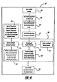
- the molding process 100 begins by opening the mold assembly 10, as indicated in block 102, to enable access to mold cavity 20. Once open, the molding ingredients used to make the composite material are inserted into the mold cavity 20, as indicated in block 104. The mold assembly 10 is then closed and mold cavity 20 is pressurized, as indicated in block 106, by moving punch 14 toward shoe plate 18. Additionally, the molding ingredients are heated to a desired temperature, as indicated in block 107. Once mold cavity 20 is closed, pressurized, and heated, the reaction process begins, as indicated in block 108.
- the reaction process may include concurrent physical reactions (e.g., heating, melting, pressurization, and phase changes) and chemical reactions.
- a desired pressure and temperature are obtained, the molding pressure and temperature are monitored and adjusted, as indicated in blocks 112 and 114, respectively, throughout the molding process.
- the molding pressure is adjusted to a predetermined optimum pressure(s), or within a range of pressure(s), depending on the material being molded.
- the temperature is adjusted to a predetermined optimum temperature(s), or within a range of temperature(s), depending on the material being molded.
- the temperature of the mold is operated above a predetermined minimum temperature, as indicated in block 116, to prevent condensation and/or recombination of gaseous reactants and/or other compounds in the pores of the gas-permeable material.
- the temperature of the mold is operated below a predetermined maximum temperature, as indicated in block 118, to control the rate of reactions in the mold cavity and to prevent decomposition of molded product.
- the present invention enables efficient molding of a composite material, such as a friction material, by venting gaseous reactants through the mold assembly without disturbing the mold cavity.
- a typical friction material could be virtually any type of material that is useful in braking systems. This would include semi-metallic friction materials, low-metallic friction materials, non-asbestos organics, ceramets, and other types known in the art.
- Common friction materials contain one or more thermosetting resinous binders (e.g., phenolic resins such as phenol-formaldehyde resins, epoxies), reinforcing fibers (e.g., aramid, steel, acrylic, mineral fibers, and the like), metal powders (e.g., iron, copper, brass, zinc, aluminum, antimony, and the like), solid lubricants (e.g., molybdenum disulfide, graphite, coke, stannic sulfide, antimony trisulfide, and the like), abrasives (e.g., tin oxide, magnesia, silica, iron oxide, alumina, rutile, and the like), organic fillers (e.g., rubber particles, cashew nut shell particles, nitrile rubber particles, and the like), and inorganic fillers (e.g., barites, gypsum, mica, titanates, and the like).
- the mixture was placed in mold cavity 20.
- the mold cavity 20 was closed by aligning top platen 16 with mold body 12.
- the mixture was molded at a temperature of 160°C and a pressure of 600 kg f /cm 2 for a total of 120 seconds.
- the gaseous reactants were vented through the gas-permeable portion 19 of punch 14 of mold assembly 10 without disturbing the closed mold cavity 20.
- the gas-permeable portion 19 was made of METAPOR® BF210AF.
- the molded product 24 was then removed from the mold cavity 20. The characteristics of molded product 24 were within the desired product specifications.
- the gaseous reactants did not decompose nor recombine or condense in the pores, and no plugging of the pores was observed.
- the mixture was placed in mold cavity 20.
- the mold cavity 20 was closed by aligning top platen 16 with mold body 12.
- the mixture was molded at a temperature of 170°C and a pressure of 600 kg f /cm 2 for a total of 120 seconds.
- the gaseous reactants were vented through the gas-permeable portion 19 of punch 14 of mold assembly 10 without disturbing the closed mold cavity 20.
- the gas-permeable portion 19 was made of METAPOR® BF210AF.
- the molded product 24 was then removed from the mold cavity 20.
- the characteristics of molded product 24 were within the desired product specifications.
- the gaseous reactants did not decompose nor recombine or condense in the pores, and no plugging of the pores was observed.
- mold punch 14 is shown as being a porous, gas-permeable material, an entirety of mold punch 14 can be a porous, gas-permeable material.
- gas-permeable portion 19 is shown as being a part of mold punch 14, top platen 16 and/or mold body 12 alternatively and/or additionally may be made of a gas-permeable material and the venting of gaseous reactants occurring therethrough.
- Examples 1 and 2 close mold assembly 10 by aligning top platen 16 with mold body 12 (as depicted in Figure 2), alternatively, top platen 16 may be pre-aligned with mold body 12, and mold cavity 20 closed though the movement of mold punch 14.
- Examples 1 and 2 form a composite friction material
- applications in which the use of such mold and molding method are advantageous include, among others, the molding of composite parts made with various synthetic thermosetting resins, such as phenolic resins (modified or unmodified), and structural components which may contain reinforcements such as solid moldings, pre-fabricated composite structures, and shaped articles such as refractory bricks.
Landscapes
- Engineering & Computer Science (AREA)
- Mechanical Engineering (AREA)
- General Engineering & Computer Science (AREA)
- Casting Or Compression Moulding Of Plastics Or The Like (AREA)
- Moulds For Moulding Plastics Or The Like (AREA)
- Manufacture Of Porous Articles, And Recovery And Treatment Of Waste Products (AREA)
Applications Claiming Priority (2)
| Application Number | Priority Date | Filing Date | Title |
|---|---|---|---|
| US10/767,620 US20050167871A1 (en) | 2004-01-29 | 2004-01-29 | Gas-permeable molds for composite material fabrication and molding method |
| US767620 | 2004-01-29 |
Publications (2)
| Publication Number | Publication Date |
|---|---|
| EP1559489A2 true EP1559489A2 (de) | 2005-08-03 |
| EP1559489A3 EP1559489A3 (de) | 2006-03-15 |
Family
ID=34654355
Family Applications (1)
| Application Number | Title | Priority Date | Filing Date |
|---|---|---|---|
| EP04030091A Withdrawn EP1559489A3 (de) | 2004-01-29 | 2004-12-18 | Gasdurchlässige Formen zum Giessen von Kompositmaterialien und Verfahren |
Country Status (3)
| Country | Link |
|---|---|
| US (1) | US20050167871A1 (de) |
| EP (1) | EP1559489A3 (de) |
| JP (1) | JP2005212485A (de) |
Cited By (2)
| Publication number | Priority date | Publication date | Assignee | Title |
|---|---|---|---|---|
| DE102007040502B4 (de) * | 2007-08-23 | 2012-06-06 | Deutsches Zentrum für Luft- und Raumfahrt e.V. | Pressvorrichtung und Verfahren zur Herstellung eines Vorkörpers für ein keramisches Bauteil |
| CN104802230A (zh) * | 2015-05-05 | 2015-07-29 | 南京林业大学 | 一种预应力增强重组竹生产模具 |
Families Citing this family (4)
| Publication number | Priority date | Publication date | Assignee | Title |
|---|---|---|---|---|
| JP2007071320A (ja) * | 2005-09-08 | 2007-03-22 | Nisshinbo Ind Inc | 摩擦部材の製造方法 |
| GB0807398D0 (en) * | 2008-04-23 | 2008-05-28 | Airbus Uk Ltd | Improved method of tape laying of thermoplastic composite materials |
| US10751982B2 (en) * | 2016-05-12 | 2020-08-25 | The Boeing Company | Methods and apparatus to remove gas and vapor from a panel for a decorative layer |
| CN109910128B (zh) * | 2019-03-18 | 2020-04-21 | 厉畅 | 木质合成板材的冲压成型机 |
Family Cites Families (31)
| Publication number | Priority date | Publication date | Assignee | Title |
|---|---|---|---|---|
| US3919446A (en) * | 1971-12-29 | 1975-11-11 | Union Carbide Corp | Process for expanding thermoformable materials and products |
| JPS61273298A (ja) * | 1985-05-28 | 1986-12-03 | Nippon Kokan Kk <Nkk> | 粉体の成形方法 |
| US5156856A (en) * | 1986-12-04 | 1992-10-20 | Ngk Insulators, Ltd. | Mold for forming molded body |
| CH675096A5 (de) * | 1987-04-09 | 1990-08-31 | Uniport Theodor Hirzel | |
| US5004089A (en) * | 1988-11-22 | 1991-04-02 | Hitachi Chemical Company, Ltd. | Clutch driven plates and method of producing the same |
| ATE119510T1 (de) * | 1990-05-09 | 1995-03-15 | Lanxide Technology Co Ltd | Makro-verbundkörper und verfahren zu ihrer herstellung. |
| DE4030964A1 (de) * | 1990-10-01 | 1992-04-02 | Happich Gmbh Gebr | Verfahren zum herstellen eines kunststofformteils |
| US5382387A (en) * | 1991-07-15 | 1995-01-17 | Bayer Aktiengesellschaft | Mouldings containing expandable graphite, their production and their use |
| JP2673623B2 (ja) * | 1991-10-01 | 1997-11-05 | 旭化成工業株式会社 | 合成樹脂の成形法 |
| US5874037A (en) * | 1993-01-21 | 1999-02-23 | Motor Wheel Corporation | Method for molding composite metal-elastomer styled wheels |
| US5489408A (en) * | 1993-03-08 | 1996-02-06 | Agency Of Industrial Science & Technology | Method for producing ceramics reinforced with three-dimensional fibers |
| US5602188A (en) * | 1993-07-13 | 1997-02-11 | Suzuki Sogyo Co., Ltd. | Biodegradable resin foam and method and apparatus for producing same |
| US5839329A (en) * | 1994-03-16 | 1998-11-24 | Baker Hughes Incorporated | Method for infiltrating preformed components and component assemblies |
| US5494432A (en) * | 1994-05-04 | 1996-02-27 | Coggins; Fred H. | Injection mold including porous mold inserts for forming a fishing lure |
| KR980700158A (ko) * | 1994-11-30 | 1998-03-30 | 유미꾸라 레이이찌 | 합성수지 성형용 금형 및 이를 이용한 성형법(Mold for Molding Synthetic Resins and Molding Method Using the Same) |
| JPH09309121A (ja) * | 1996-05-23 | 1997-12-02 | Akebono Brake Res & Dev Center Ltd | 熱プレス装置 |
| US5882517A (en) * | 1996-09-10 | 1999-03-16 | Cuno Incorporated | Porous structures |
| JPH10122284A (ja) * | 1996-10-18 | 1998-05-12 | Tokico Ltd | ブレーキパッド成形用金型 |
| US5971113A (en) * | 1997-03-10 | 1999-10-26 | Alliedsignal Inc. | Coated friction pad for brake assembly |
| US6220405B1 (en) * | 1997-07-02 | 2001-04-24 | Alliedsignal Inc. | Friction material for drum-in-hat disc brake assembly |
| JPH11100206A (ja) * | 1997-09-29 | 1999-04-13 | Honda Motor Co Ltd | 炭素材料 |
| US6164953A (en) * | 1998-03-12 | 2000-12-26 | Patent Holding Company | Method and mold to make plastic articles having reduced surface defects and assembly for use therein |
| DE19907279A1 (de) * | 1999-02-21 | 2000-08-31 | Gefinex Polymerschaeume Gmbh | Formteilautomat zur Herstellung von Kunststoffschaumprodukten aus Beads |
| US6228815B1 (en) * | 1999-06-29 | 2001-05-08 | Alliedsignal Inc. | Solid lubricants containing bismuth sulfide for use in friction lining |
| US6367765B1 (en) * | 1999-09-09 | 2002-04-09 | Klaus A. Wieder | Mold vent |
| US6467531B1 (en) * | 1999-10-18 | 2002-10-22 | Clyde D. Doney | Method and apparatus for producing investment castings in a vacuum |
| DE19953438C2 (de) * | 1999-11-06 | 2002-04-04 | Ruetgers Automotive Ag | Verfahren und Vorrichtung zur Herstellung von Bremsbelägen |
| US6554054B2 (en) * | 2001-01-04 | 2003-04-29 | Charles H. Noble | Method and apparatus for centrifugal casting |
| JP2002240042A (ja) * | 2001-02-15 | 2002-08-28 | Bridgestone Corp | タイヤ加硫成型用金型 |
| US6637497B2 (en) * | 2001-05-08 | 2003-10-28 | David J. Herron | Automotive and aerospace materials in a continuous, pressurized mold filling and casting machine |
| US6776942B2 (en) * | 2001-11-20 | 2004-08-17 | Taylor Made Golf Company, Inc. | Mold for making golf balls and methods for using it |
-
2004
- 2004-01-29 US US10/767,620 patent/US20050167871A1/en not_active Abandoned
- 2004-12-18 EP EP04030091A patent/EP1559489A3/de not_active Withdrawn
-
2005
- 2005-01-31 JP JP2005023071A patent/JP2005212485A/ja active Pending
Cited By (3)
| Publication number | Priority date | Publication date | Assignee | Title |
|---|---|---|---|---|
| DE102007040502B4 (de) * | 2007-08-23 | 2012-06-06 | Deutsches Zentrum für Luft- und Raumfahrt e.V. | Pressvorrichtung und Verfahren zur Herstellung eines Vorkörpers für ein keramisches Bauteil |
| CN104802230A (zh) * | 2015-05-05 | 2015-07-29 | 南京林业大学 | 一种预应力增强重组竹生产模具 |
| CN104802230B (zh) * | 2015-05-05 | 2017-01-18 | 南京林业大学 | 一种预应力增强重组竹生产模具 |
Also Published As
| Publication number | Publication date |
|---|---|
| US20050167871A1 (en) | 2005-08-04 |
| EP1559489A3 (de) | 2006-03-15 |
| JP2005212485A (ja) | 2005-08-11 |
Similar Documents
| Publication | Publication Date | Title |
|---|---|---|
| EP2050836B1 (de) | Vorformling für verbundwerkstoff und herstellungsverfahren dafür | |
| CN102119289B (zh) | 用于制动系统,尤其是用于盘式制动器的制动衬块 | |
| US7252499B2 (en) | Apparatus for unidirectional infiltration of preform with molten resin or pitch | |
| EP1559489A2 (de) | Gasdurchlässige Formen zum Giessen von Kompositmaterialien und Verfahren | |
| CN108138031B (zh) | 摩擦材料 | |
| US20030118757A1 (en) | Process for producing hollow bodies comprising fibre-reinforced ceramic materials | |
| WO2005056262A8 (en) | Binderless preform manufacturing method and mold therefore | |
| EP0943832A2 (de) | Reibmaterial | |
| US5360587A (en) | Preparation of friction elements and compositions therefor | |
| JP2003160802A (ja) | 粉末成形体およびその製造方法並びに多孔質焼結体の製造方法 | |
| US3505446A (en) | Friction elements | |
| KR100776485B1 (ko) | 마찰부재의 제조방법 | |
| US20040035657A1 (en) | Method for producing ceramic brake disks from bmc | |
| JP6507698B2 (ja) | 摩擦材用造粒物およびこれを用いた摩擦材の製造方法 | |
| US5714525A (en) | Preparation of friction elements and compositions therefor | |
| EP0648564A2 (de) | Verfahren zur Herstellung eines luftdurchlässigen Formkörpers | |
| JP2003127155A (ja) | 摩擦材の熱成形過程のガス抜き方法 | |
| JP3228096B2 (ja) | 摩擦材の製造方法 | |
| JP2003145565A (ja) | 摩擦材の製造方法 | |
| CA2128756C (en) | Preparation of friction elements and compositions therefor | |
| JP4481941B2 (ja) | 複合材用プリフォームの製造方法 | |
| JPS5928447B2 (ja) | 耐火物の製造方法及び装置 | |
| KR100809803B1 (ko) | 마찰부재의 제조방법 | |
| EP3124455B1 (de) | Verfahren zur herstellung eines faserverstärkten kohlenstoff-keramikmaterial-verbundwerkstoffs | |
| JPH07116303B2 (ja) | 摩擦板の製造法 |
Legal Events
| Date | Code | Title | Description |
|---|---|---|---|
| PUAI | Public reference made under article 153(3) epc to a published international application that has entered the european phase |
Free format text: ORIGINAL CODE: 0009012 |
|
| AK | Designated contracting states |
Kind code of ref document: A2 Designated state(s): AT BE BG CH CY CZ DE DK EE ES FI FR GB GR HU IE IS IT LI LT LU MC NL PL PT RO SE SI SK TR |
|
| AX | Request for extension of the european patent |
Extension state: AL BA HR LV MK YU |
|
| PUAL | Search report despatched |
Free format text: ORIGINAL CODE: 0009013 |
|
| AK | Designated contracting states |
Kind code of ref document: A3 Designated state(s): AT BE BG CH CY CZ DE DK EE ES FI FR GB GR HU IE IS IT LI LT LU MC NL PL PT RO SE SI SK TR |
|
| AX | Request for extension of the european patent |
Extension state: AL BA HR LV MK YU |
|
| RIC1 | Information provided on ipc code assigned before grant |
Ipc: F16D 69/04 20060101ALI20060120BHEP Ipc: B22C 9/00 20060101AFI20050523BHEP |
|
| 17P | Request for examination filed |
Effective date: 20060701 |
|
| STAA | Information on the status of an ep patent application or granted ep patent |
Free format text: STATUS: THE APPLICATION HAS BEEN WITHDRAWN |
|
| AKX | Designation fees paid |
Designated state(s): DE FR GB IT |
|
| 18W | Application withdrawn |
Effective date: 20061018 |