EP1557785A1 - Système de balayage multi-faisceaux avec correction parallèle de l'intensité - Google Patents
Système de balayage multi-faisceaux avec correction parallèle de l'intensité Download PDFInfo
- Publication number
- EP1557785A1 EP1557785A1 EP05100295A EP05100295A EP1557785A1 EP 1557785 A1 EP1557785 A1 EP 1557785A1 EP 05100295 A EP05100295 A EP 05100295A EP 05100295 A EP05100295 A EP 05100295A EP 1557785 A1 EP1557785 A1 EP 1557785A1
- Authority
- EP
- European Patent Office
- Prior art keywords
- array
- programmable
- light
- scanning system
- intensity
- Prior art date
- Legal status (The legal status is an assumption and is not a legal conclusion. Google has not performed a legal analysis and makes no representation as to the accuracy of the status listed.)
- Withdrawn
Links
Images

Classifications
-
- G—PHYSICS
- G06—COMPUTING; CALCULATING OR COUNTING
- G06K—GRAPHICAL DATA READING; PRESENTATION OF DATA; RECORD CARRIERS; HANDLING RECORD CARRIERS
- G06K15/00—Arrangements for producing a permanent visual presentation of the output data, e.g. computer output printers
- G06K15/02—Arrangements for producing a permanent visual presentation of the output data, e.g. computer output printers using printers
- G06K15/12—Arrangements for producing a permanent visual presentation of the output data, e.g. computer output printers using printers by photographic printing, e.g. by laser printers
- G06K15/1204—Arrangements for producing a permanent visual presentation of the output data, e.g. computer output printers using printers by photographic printing, e.g. by laser printers involving the fast moving of an optical beam in the main scanning direction
- G06K15/1209—Intensity control of the optical beam
- G06K15/1214—Intensity control of the optical beam by feedback
-
- G—PHYSICS
- G02—OPTICS
- G02B—OPTICAL ELEMENTS, SYSTEMS OR APPARATUS
- G02B26/00—Optical devices or arrangements for the control of light using movable or deformable optical elements
- G02B26/08—Optical devices or arrangements for the control of light using movable or deformable optical elements for controlling the direction of light
- G02B26/10—Scanning systems
- G02B26/12—Scanning systems using multifaceted mirrors
- G02B26/123—Multibeam scanners, e.g. using multiple light sources or beam splitters
-
- G—PHYSICS
- G02—OPTICS
- G02B—OPTICAL ELEMENTS, SYSTEMS OR APPARATUS
- G02B26/00—Optical devices or arrangements for the control of light using movable or deformable optical elements
- G02B26/08—Optical devices or arrangements for the control of light using movable or deformable optical elements for controlling the direction of light
- G02B26/10—Scanning systems
- G02B26/12—Scanning systems using multifaceted mirrors
- G02B26/127—Adaptive control of the scanning light beam, e.g. using the feedback from one or more detectors
-
- G—PHYSICS
- G06—COMPUTING; CALCULATING OR COUNTING
- G06K—GRAPHICAL DATA READING; PRESENTATION OF DATA; RECORD CARRIERS; HANDLING RECORD CARRIERS
- G06K15/00—Arrangements for producing a permanent visual presentation of the output data, e.g. computer output printers
- G06K15/02—Arrangements for producing a permanent visual presentation of the output data, e.g. computer output printers using printers
- G06K15/12—Arrangements for producing a permanent visual presentation of the output data, e.g. computer output printers using printers by photographic printing, e.g. by laser printers
- G06K15/1238—Arrangements for producing a permanent visual presentation of the output data, e.g. computer output printers using printers by photographic printing, e.g. by laser printers simultaneously exposing more than one point
- G06K15/1257—Arrangements for producing a permanent visual presentation of the output data, e.g. computer output printers using printers by photographic printing, e.g. by laser printers simultaneously exposing more than one point on more than one main scanning line
- G06K15/1261—Arrangements for producing a permanent visual presentation of the output data, e.g. computer output printers using printers by photographic printing, e.g. by laser printers simultaneously exposing more than one point on more than one main scanning line using an array of light sources
Definitions
- the present invention relates generally to the field of optical imaging. More specifically, the invention relates to xerographic printers and, more particularly, to xerographic printers that incorporate a Vertical Cavity Surface Emitting Laser (VCSEL) array w hose output is corrected by beam intensity variations through the use of process control electronics.
- VCSEL Vertical Cavity Surface Emitting Laser
- Polygon Raster Output Scanner (ROS) printers typically consist of a modulating laser light source, a polygon scanning beam deflector, an optical system of lenses and mirrors, a xerographic marking engine and the electronics to control printer operation.
- the ROS is positioned in an optical scan system to write an image on a moving photoreceptor surface.
- a modulated beam is directed onto the facets of a rotating polygon mirror, which then sweeps the reflected beam across the photoreceptor surface. Each sweep exposes a raster line to a linear segment of a video signal image.
- the modulating laser light source may consist of a Vertical Cavity Surface Emitting Laser (VCSEL) array.
- the VCSEL array may be either a one or two-dimensional array of individual laser sources.
- Each individual laser source in the VCSEL array has a corresponding drive circuit which may be used to generate a beam to expose a corresponding area on a moving photoreceptor in response to video data information applied to the drive circuits of the VCSEL array.
- the photoreceptor is advanced in the process direction to provide a desired image by the formation of sequential scan lines generated by the beam to beam exposure delivered from the VCSEL array.
- Current beam to beam uniformity correction in multi-beam ROS systems multiplexes one photo detector and one loop-back system among all the beams. This is accomplished by sequentially selecting each beam and comparing the output of the photo detector for that beam with a "reference " to decide whether to increase or decrease the power intensity in the selected beam. This sequential detection and power adjustment process takes a few micro-seconds per beam. In a high performance multi-beam ROS system the beam to beam uniformity correction has to be fine-tuned for each beam per scan line. In a VCSEL ROS system incorporating a two-dimensional array for producing a plurality of beams, the sequential beam to beam uniformity correction may take up to a few hundred micro-seconds. This uniformity correction scheme presents an amount of delay time for each line to be printed such that it renders the sequential multiplexing of all the beams unusable for high speed/high performance platforms.
- the electro-optical system for adjusting beam to beam power non-uniformity in a multi-beam scanning system is disclosed.
- the electro-optical system consists of NxM array of light beams and NxM array of photodetectors wherein optical means deflect the light beams onto a photodetector array.
- a circuit consisting of NxM array of programmable laser drivers programmed with uniformity values for each light beam and having an NxM array of feedback loops is used to adjust the power intensity of each beam through the programmable laser drivers wherein each programmable laser driver uses the photodetector array summed with non-linearity inputs to adjust for beam to beam power uniformity correction.
- the method further comprises:
- said programmable laser drivers modulates each light beam statically for producing parallel uniform beam to beam light intensity.
- said programmable laser driver modulates each light beam dynamically for producing parallel uniform beam to beam light intensity.
- said NxM array of light beams is a vertical cavity surface emitting laser array.
- a multi-beam scanning system comprising an array of light sources each having a programmable reference mechanism or driver programmed with calibrated uniformity values for producing a corresponding light beam for producing a corresponding power intensity of light beams is described.
- the multi-beam scanning system includes a beam splitter to deflect the light beams onto a photodetector array wherein an array of feedback loops simultaneously adjust the power intensity in the fast/slow scan direction for each light beam by using the programmable reference mechansims or drivers.
- Each programmable driver uses a photodetector on the photodetector array to adjust for parallel beam to beam power correction produced from the array of light sources.
- the optical source may be either a one or two-dimensional array of light sources each light source producing light beams of unequal power intensity.
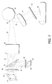
- the optical source 10 shown is a two dimensional NxM laser array 10 of Vertical Cavity Surface Emitting Lasers (VCSELs), all emitting nominally the same wavelength and same polarization state.
- the individual VCSELs 12 in the VCSEL NxM array 10 are arranged vertically and horizontally in each scan plane direction with equal center to center spacing between the individual VCSELs 12 .
- the VCSEL NxM array 10 may be monolithic in one embodiment wherein "N" and "M" may be any combination of integer values greater than zero to describe the two-dimensional array.
- the VCSELs 12 each emit beams 14 through a collimator lens 60 wherein the beams 14 pass through a beam splitter or mirror 16 and then through a pre-polygon lens system 23 .
- the lens system 23 focuses the beams 14 into a controlled energy distribution beam 25 that is reflected from the mirrored facets 27 of a rotating polygon scanner 70 .
- the light beam 25 is reflected from each illuminated facet 27 and passes through a series of post-polygon lenses 15 and 19 , respectively, which scans the beam 25 across a surface of a photoreceptor 20.
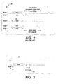
- Beam to beam uniformity correction in multi-beam ROS systems multiplexes one photo detector and one loop-back system among all the beams. This may be accomplished by sequentially selecting each beam 32 and comparing the output of a photo detector for that beam with a "reference " to decide whether to increase or decrease the power intensity in the selected beam 32 .
- a sequential detection and power adjustment process may take greater than 100 micro-seconds for beam to beam correction during line synchronization 30 .
- What would be desirable is a parallel detection and power adjustment scheme. As shown in FIG. 3 using parallel beam to beam uniformity correction reduces the time 40 to that of adjusting the power correction for an individual VCSEL beam 14 when calibrating and adjusting for all the beams 38 during the line synchronization operation 30 .
- each individual beam 14 from each individual VCSEL 12 is split by the beam splitter 16 for generating a beam 18 for passing through an imaging lens 62 for receipt on an photo detector plane 64 having photo detectors 42 .
- the photo detector plane 64 has the photo detectors 42 arranged in a NxM array to match the corresponding VCSELs 12 on the VCSEL NxM array 10 . All the VCSELs in the NxM array 10 may now be addressed at the same time in parallel on the photo detector plane 64 .
- the output of each photo detector 42 may now be used for each beam 18 corresponding to a beam 14 from the VCSEL array 10 as a "reference " to decide whether to increase or decrease the power intensity for a given selected VCSEL 12 .
- FIG. 5 is a simplified circuit diagram for calibrating and providing parallel beam to beam uniformity and power correction for a VCSEL ROS of NxM array beams using the architecture shown in FIG. 1 .
- the following is one method in embodiments that may be used to calibrate the multi-beam VCSEL array 10 for parallel beam to beam uniformity correction.
- One method used to obtain calibration values is to first turn all the beams 32 "ON" and close the switch S1 44 shown in FIG. 5 .
- the intensity of each beam 18 at the photo detector plane 64 is either manually or automatically calibrated for a nominal value on the surface of the photoreceptor 20 through use of a programmable uniformity control reference mechanism or driver.
- the programmable uniformity control reference mechanism or driver may be in one embodiment an eight "8" bit digital to analog (D to A) converter 28 that varies the amount of current into each light source for varying the intensity of each corresponding light beam produced.
- a photo detector 42 is used to measure the output power intensity of each beam 18 for the corresponding beam 14 . Therefore, each VCSEL 12 has a corresponding calibrated D to A converter 47 used to uniformly adjust the intensity of each beam 14 such that they are all of equal strength.
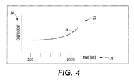
- FIG. 4 illustrates a graph showing one example of a correction coefficient curve for long term power compensation wherein the uniformity values may be modified to compensate for long term aging of the VCSELs 12 at predetermined intervals. This may be determined through cycle testing during machine set-up time, or by multiplying the uniformity values by a time varying empirically/mathematically derived coefficient to compensate for long term power compensation.
- the correction coefficient may also be implemented within the D to A converters as part of the calibration process and for real time operation as described below.
- the calibrated uniformity reference values for each beam are set by loading these values into the D to A converters 28 through 47 for each beam during machine set-up time.
- switch S1 44 is closed simultaneously for each VCSEL 12 to establish a closed loop for beam to beam uniformity correction.
- Summing amplifier 46 uses the value from the photo detectors 42 and sums it with the different reference values stored in each of the D to A converters. By dedicating one cycle time, ⁇ 2 Usec or less, per scan line, parallel beam to beam uniformity correction is achieved. M ore specifically, during this cycle, all beams are turned to "ON" and the closed-loop automatically modifies the light intensity of each beam to match that of the reference value. This reduces the existing sequential/serial approach to the power adjustment of the light beams from an unacceptable level of a few hundred Usec per line to approximately 2 Usec per line or lower which provides a manageable overhead in very high performance imaging applications.
- the reference value for each beam is set by loading uniformity values into the D to A converters 28 during machine set-up time.
- a closed-loop is once again established by closing switch S1 44 and dedicating one cycle time, ⁇ 2 Usec or less, per scan line for parallel beam to beam static power correction, i.e., loading a new value of a Smile 52 correction value into the corresponding input.
- Real time/dynamic power correction 50 in the fast/slow scan direction may be implemented by driving other inputs into a summing amplifier 48 as depicted in FIG. 5 .
- These inputs could represent Droop 54 or other system non-linearity(s) 56 like vibration that may be corrected by modulating the beam intensity statically or dynamically.
Landscapes
- Physics & Mathematics (AREA)
- Optics & Photonics (AREA)
- Engineering & Computer Science (AREA)
- General Physics & Mathematics (AREA)
- General Engineering & Computer Science (AREA)
- Theoretical Computer Science (AREA)
- Mechanical Optical Scanning Systems (AREA)
- Laser Beam Printer (AREA)
Applications Claiming Priority (2)
| Application Number | Priority Date | Filing Date | Title |
|---|---|---|---|
| US10/762,178 US7119825B2 (en) | 2004-01-21 | 2004-01-21 | Parallel beam to beam power correction |
| US762178 | 2004-01-21 |
Publications (1)
| Publication Number | Publication Date |
|---|---|
| EP1557785A1 true EP1557785A1 (fr) | 2005-07-27 |
Family
ID=34634590
Family Applications (1)
| Application Number | Title | Priority Date | Filing Date |
|---|---|---|---|
| EP05100295A Withdrawn EP1557785A1 (fr) | 2004-01-21 | 2005-01-19 | Système de balayage multi-faisceaux avec correction parallèle de l'intensité |
Country Status (3)
| Country | Link |
|---|---|
| US (1) | US7119825B2 (fr) |
| EP (1) | EP1557785A1 (fr) |
| JP (1) | JP4578250B2 (fr) |
Cited By (1)
| Publication number | Priority date | Publication date | Assignee | Title |
|---|---|---|---|---|
| EP1775622A1 (fr) * | 2005-10-12 | 2007-04-18 | Canon Kabushiki Kaisha | Appareil de balayage optique et appareil de formation d'images l'utilisant |
Families Citing this family (4)
| Publication number | Priority date | Publication date | Assignee | Title |
|---|---|---|---|---|
| US7710443B2 (en) * | 2007-02-28 | 2010-05-04 | Hewlett-Packard Development Company, L.P. | Providing data |
| EP1995641B1 (fr) * | 2007-05-24 | 2014-08-27 | Ricoh Company, Ltd. | Procédé et appareil de formation d'images |
| JP5006810B2 (ja) * | 2008-02-06 | 2012-08-22 | 株式会社リコー | 光走査装置及び画像形成装置 |
| JP5333982B2 (ja) * | 2008-03-17 | 2013-11-06 | 株式会社リコー | 光源装置、光走査装置及び画像形成装置 |
Citations (7)
| Publication number | Priority date | Publication date | Assignee | Title |
|---|---|---|---|---|
| US4796265A (en) * | 1986-04-05 | 1989-01-03 | Ricoh Company, Limited | Imaging using collectively controlled multiple beams |
| US5165074A (en) * | 1990-08-20 | 1992-11-17 | Xerox Corporation | Means and method for controlling raster output scanner intensity |
| US5432537A (en) * | 1992-05-18 | 1995-07-11 | Ricoh Company, Ltd. | Optical recording apparatus capable of controlling optical power of laser diode array |
| EP0695078A1 (fr) * | 1994-07-29 | 1996-01-31 | Xerox Corporation | Correction rapide de spot de balayage pour un polygone à balayage de trame |
| EP0710005A2 (fr) * | 1994-10-31 | 1996-05-01 | Hewlett-Packard Company | Commande de la taille des points dans un appareil de formation d'image avec laser |
| EP0829933A2 (fr) * | 1996-09-16 | 1998-03-18 | Xerox Corporation | Ensemble intégral VCSEL à rétroaction |
| US6603498B1 (en) * | 2000-11-28 | 2003-08-05 | Coherent, Inc. | Printer head with linear array of individually addressable diode-lasers |
Family Cites Families (8)
| Publication number | Priority date | Publication date | Assignee | Title |
|---|---|---|---|---|
| US4751377A (en) * | 1985-12-27 | 1988-06-14 | Fuji Photo Film Co., Ltd. | Light beam scanning recording apparatus and method of correcting intensity of image to be recorded thereby |
| US5151718A (en) * | 1990-12-31 | 1992-09-29 | Texas Instruments Incorporated | System and method for solid state illumination for dmd devices |
| JPH0519197A (ja) * | 1991-07-10 | 1993-01-29 | Ricoh Co Ltd | 半導体レーザアレーを用いた光学装置 |
| US5461413A (en) * | 1991-07-22 | 1995-10-24 | At&T Ipm Corp. | Laser array printing |
| US5917534A (en) * | 1995-06-29 | 1999-06-29 | Eastman Kodak Company | Light-emitting diode arrays with integrated photodetectors formed as a monolithic device and methods and apparatus for using same |
| US5956070A (en) * | 1995-12-22 | 1999-09-21 | Xerox Corporation | Color xerographic printer with multiple linear arrays of surface emitting lasers with dissimilar polarization states and dissimilar wavelengths |
| US6121983A (en) * | 1998-11-19 | 2000-09-19 | Xerox Corporation | Method and apparatus for a solid state laser scanning architecture |
| US20050157160A1 (en) * | 2004-01-21 | 2005-07-21 | Xerox Corporation | Parallel beam to beam uniformity correction |
-
2004
- 2004-01-21 US US10/762,178 patent/US7119825B2/en active Active
-
2005
- 2005-01-14 JP JP2005007256A patent/JP4578250B2/ja not_active Expired - Fee Related
- 2005-01-19 EP EP05100295A patent/EP1557785A1/fr not_active Withdrawn
Patent Citations (7)
| Publication number | Priority date | Publication date | Assignee | Title |
|---|---|---|---|---|
| US4796265A (en) * | 1986-04-05 | 1989-01-03 | Ricoh Company, Limited | Imaging using collectively controlled multiple beams |
| US5165074A (en) * | 1990-08-20 | 1992-11-17 | Xerox Corporation | Means and method for controlling raster output scanner intensity |
| US5432537A (en) * | 1992-05-18 | 1995-07-11 | Ricoh Company, Ltd. | Optical recording apparatus capable of controlling optical power of laser diode array |
| EP0695078A1 (fr) * | 1994-07-29 | 1996-01-31 | Xerox Corporation | Correction rapide de spot de balayage pour un polygone à balayage de trame |
| EP0710005A2 (fr) * | 1994-10-31 | 1996-05-01 | Hewlett-Packard Company | Commande de la taille des points dans un appareil de formation d'image avec laser |
| EP0829933A2 (fr) * | 1996-09-16 | 1998-03-18 | Xerox Corporation | Ensemble intégral VCSEL à rétroaction |
| US6603498B1 (en) * | 2000-11-28 | 2003-08-05 | Coherent, Inc. | Printer head with linear array of individually addressable diode-lasers |
Cited By (4)
| Publication number | Priority date | Publication date | Assignee | Title |
|---|---|---|---|---|
| EP1775622A1 (fr) * | 2005-10-12 | 2007-04-18 | Canon Kabushiki Kaisha | Appareil de balayage optique et appareil de formation d'images l'utilisant |
| KR100856154B1 (ko) * | 2005-10-12 | 2008-09-03 | 캐논 가부시끼가이샤 | 주사광학장치 및 그것을 이용한 화상형성장치 |
| US7466333B2 (en) | 2005-10-12 | 2008-12-16 | Canon Kabushiki Kaisha | Optical scanning apparatus and image-forming apparatus using the same |
| US8063927B2 (en) | 2005-10-12 | 2011-11-22 | Canon Kabushiki Kaisha | Optical scanning apparatus and image-forming apparatus using the same |
Also Published As
| Publication number | Publication date |
|---|---|
| US7119825B2 (en) | 2006-10-10 |
| JP2005208642A (ja) | 2005-08-04 |
| US20050157155A1 (en) | 2005-07-21 |
| JP4578250B2 (ja) | 2010-11-10 |
Similar Documents
| Publication | Publication Date | Title |
|---|---|---|
| EP1557786A2 (fr) | Correction en parallèle de l'uniformité de rayon à rayon. | |
| US7253386B2 (en) | Method and apparatus for monitoring and controlling laser intensity in a ROS scanning system | |
| JPH05224141A (ja) | 可変波長光源を用いた光学出力装置でのスポット位置制御用の装置とシステム | |
| JPH01105268A (ja) | 情報記録用光ビ−ムの出力安定化方法及び装置 | |
| EP1557785A1 (fr) | Système de balayage multi-faisceaux avec correction parallèle de l'intensité | |
| US5278405A (en) | Method and apparatus for the correction of positioning errors of a deflected light ray | |
| US9188902B2 (en) | Image forming apparatus and correction data generation method | |
| JPH09197313A (ja) | マルチビーム光走査装置 | |
| JPH05224140A (ja) | 可変波長光源を用いた光学出力装置でのスポット位置制御方法 | |
| US8520711B2 (en) | Optical device and method for controlling the same | |
| JP3291341B2 (ja) | スポット位置制御装置 | |
| JPS63209270A (ja) | 半導体レ−ザのドル−プ補正装置 | |
| KR100797717B1 (ko) | 빔주사 타이밍 및 빔량의 조절 방법 및 그를 이용한 주사장치 | |
| JP3707073B2 (ja) | 光量制御方法 | |
| US20030189635A1 (en) | Method for calibrating spatial light modulator against profile | |
| US8593495B2 (en) | Image forming apparatus that forms image by scanning photosensitive member with multiple beams | |
| JPH0933832A (ja) | 光走査装置および光走査装置におけるレーザビーム変調方法 | |
| JP2003270564A (ja) | 光走査装置 | |
| US5671078A (en) | Accurate laser power control for dual/multiple beams | |
| US8115795B2 (en) | Two-dimensional ROS emitter geometry with low banding sensitivity | |
| US20060109088A1 (en) | Spatial light modulator calibration | |
| JP2002267967A (ja) | 複数ビーム光量制御装置 | |
| JPS63204869A (ja) | レ−ザ記録方法および装置 | |
| JPS63175573A (ja) | レ−ザ記録装置 | |
| JP3562742B2 (ja) | 光ビーム出力制御装置 |
Legal Events
| Date | Code | Title | Description |
|---|---|---|---|
| PUAI | Public reference made under article 153(3) epc to a published international application that has entered the european phase |
Free format text: ORIGINAL CODE: 0009012 |
|
| AK | Designated contracting states |
Kind code of ref document: A1 Designated state(s): AT BE BG CH CY CZ DE DK EE ES FI FR GB GR HU IE IS IT LI LT LU MC NL PL PT RO SE SI SK TR |
|
| AX | Request for extension of the european patent |
Extension state: AL BA HR LV MK YU |
|
| 17P | Request for examination filed |
Effective date: 20060127 |
|
| AKX | Designation fees paid |
Designated state(s): DE FR GB |
|
| 17Q | First examination report despatched |
Effective date: 20090506 |
|
| STAA | Information on the status of an ep patent application or granted ep patent |
Free format text: STATUS: THE APPLICATION IS DEEMED TO BE WITHDRAWN |
|
| 18D | Application deemed to be withdrawn |
Effective date: 20090917 |