EP1557622A2 - Mikrokanal-Verflüssiger - Google Patents
Mikrokanal-Verflüssiger Download PDFInfo
- Publication number
- EP1557622A2 EP1557622A2 EP05250232A EP05250232A EP1557622A2 EP 1557622 A2 EP1557622 A2 EP 1557622A2 EP 05250232 A EP05250232 A EP 05250232A EP 05250232 A EP05250232 A EP 05250232A EP 1557622 A2 EP1557622 A2 EP 1557622A2
- Authority
- EP
- European Patent Office
- Prior art keywords
- condenser
- microchannel
- microchannel condenser
- coils
- refrigerant
- Prior art date
- Legal status (The legal status is an assumption and is not a legal conclusion. Google has not performed a legal analysis and makes no representation as to the accuracy of the status listed.)
- Granted
Links
Images


Classifications
-
- F—MECHANICAL ENGINEERING; LIGHTING; HEATING; WEAPONS; BLASTING
- F25—REFRIGERATION OR COOLING; COMBINED HEATING AND REFRIGERATION SYSTEMS; HEAT PUMP SYSTEMS; MANUFACTURE OR STORAGE OF ICE; LIQUEFACTION SOLIDIFICATION OF GASES
- F25B—REFRIGERATION MACHINES, PLANTS OR SYSTEMS; COMBINED HEATING AND REFRIGERATION SYSTEMS; HEAT PUMP SYSTEMS
- F25B39/00—Evaporators; Condensers
- F25B39/04—Condensers
-
- F—MECHANICAL ENGINEERING; LIGHTING; HEATING; WEAPONS; BLASTING
- F28—HEAT EXCHANGE IN GENERAL
- F28B—STEAM OR VAPOUR CONDENSERS
- F28B1/00—Condensers in which the steam or vapour is separate from the cooling medium by walls, e.g. surface condenser
- F28B1/06—Condensers in which the steam or vapour is separate from the cooling medium by walls, e.g. surface condenser using air or other gas as the cooling medium
-
- F—MECHANICAL ENGINEERING; LIGHTING; HEATING; WEAPONS; BLASTING
- F28—HEAT EXCHANGE IN GENERAL
- F28D—HEAT-EXCHANGE APPARATUS, NOT PROVIDED FOR IN ANOTHER SUBCLASS, IN WHICH THE HEAT-EXCHANGE MEDIA DO NOT COME INTO DIRECT CONTACT
- F28D1/00—Heat-exchange apparatus having stationary conduit assemblies for one heat-exchange medium only, the media being in contact with different sides of the conduit wall, in which the other heat-exchange medium is a large body of fluid, e.g. domestic or motor car radiators
- F28D1/02—Heat-exchange apparatus having stationary conduit assemblies for one heat-exchange medium only, the media being in contact with different sides of the conduit wall, in which the other heat-exchange medium is a large body of fluid, e.g. domestic or motor car radiators with heat-exchange conduits immersed in the body of fluid
- F28D1/04—Heat-exchange apparatus having stationary conduit assemblies for one heat-exchange medium only, the media being in contact with different sides of the conduit wall, in which the other heat-exchange medium is a large body of fluid, e.g. domestic or motor car radiators with heat-exchange conduits immersed in the body of fluid with tubular conduits
- F28D1/053—Heat-exchange apparatus having stationary conduit assemblies for one heat-exchange medium only, the media being in contact with different sides of the conduit wall, in which the other heat-exchange medium is a large body of fluid, e.g. domestic or motor car radiators with heat-exchange conduits immersed in the body of fluid with tubular conduits the conduits being straight
- F28D1/0535—Heat-exchange apparatus having stationary conduit assemblies for one heat-exchange medium only, the media being in contact with different sides of the conduit wall, in which the other heat-exchange medium is a large body of fluid, e.g. domestic or motor car radiators with heat-exchange conduits immersed in the body of fluid with tubular conduits the conduits being straight the conduits having a non-circular cross-section
- F28D1/05366—Assemblies of conduits connected to common headers, e.g. core type radiators
- F28D1/05383—Assemblies of conduits connected to common headers, e.g. core type radiators with multiple rows of conduits or with multi-channel conduits
-
- F—MECHANICAL ENGINEERING; LIGHTING; HEATING; WEAPONS; BLASTING
- F28—HEAT EXCHANGE IN GENERAL
- F28F—DETAILS OF HEAT-EXCHANGE AND HEAT-TRANSFER APPARATUS, OF GENERAL APPLICATION
- F28F9/00—Casings; Header boxes; Auxiliary supports for elements; Auxiliary members within casings
- F28F9/007—Auxiliary supports for elements
- F28F9/013—Auxiliary supports for elements for tubes or tube-assemblies
-
- F—MECHANICAL ENGINEERING; LIGHTING; HEATING; WEAPONS; BLASTING
- F28—HEAT EXCHANGE IN GENERAL
- F28F—DETAILS OF HEAT-EXCHANGE AND HEAT-TRANSFER APPARATUS, OF GENERAL APPLICATION
- F28F9/00—Casings; Header boxes; Auxiliary supports for elements; Auxiliary members within casings
- F28F9/26—Arrangements for connecting different sections of heat-exchange elements, e.g. of radiators
- F28F9/262—Arrangements for connecting different sections of heat-exchange elements, e.g. of radiators for radiators
-
- F—MECHANICAL ENGINEERING; LIGHTING; HEATING; WEAPONS; BLASTING
- F25—REFRIGERATION OR COOLING; COMBINED HEATING AND REFRIGERATION SYSTEMS; HEAT PUMP SYSTEMS; MANUFACTURE OR STORAGE OF ICE; LIQUEFACTION SOLIDIFICATION OF GASES
- F25B—REFRIGERATION MACHINES, PLANTS OR SYSTEMS; COMBINED HEATING AND REFRIGERATION SYSTEMS; HEAT PUMP SYSTEMS
- F25B2400/00—General features or devices for refrigeration machines, plants or systems, combined heating and refrigeration systems or heat-pump systems, i.e. not limited to a particular subgroup of F25B
- F25B2400/22—Refrigeration systems for supermarkets
-
- F—MECHANICAL ENGINEERING; LIGHTING; HEATING; WEAPONS; BLASTING
- F25—REFRIGERATION OR COOLING; COMBINED HEATING AND REFRIGERATION SYSTEMS; HEAT PUMP SYSTEMS; MANUFACTURE OR STORAGE OF ICE; LIQUEFACTION SOLIDIFICATION OF GASES
- F25B—REFRIGERATION MACHINES, PLANTS OR SYSTEMS; COMBINED HEATING AND REFRIGERATION SYSTEMS; HEAT PUMP SYSTEMS
- F25B2500/00—Problems to be solved
- F25B2500/01—Geometry problems, e.g. for reducing size
-
- F—MECHANICAL ENGINEERING; LIGHTING; HEATING; WEAPONS; BLASTING
- F25—REFRIGERATION OR COOLING; COMBINED HEATING AND REFRIGERATION SYSTEMS; HEAT PUMP SYSTEMS; MANUFACTURE OR STORAGE OF ICE; LIQUEFACTION SOLIDIFICATION OF GASES
- F25B—REFRIGERATION MACHINES, PLANTS OR SYSTEMS; COMBINED HEATING AND REFRIGERATION SYSTEMS; HEAT PUMP SYSTEMS
- F25B2500/00—Problems to be solved
- F25B2500/19—Calculation of parameters
-
- F—MECHANICAL ENGINEERING; LIGHTING; HEATING; WEAPONS; BLASTING
- F28—HEAT EXCHANGE IN GENERAL
- F28F—DETAILS OF HEAT-EXCHANGE AND HEAT-TRANSFER APPARATUS, OF GENERAL APPLICATION
- F28F2260/00—Heat exchangers or heat exchange elements having special size, e.g. microstructures
- F28F2260/02—Heat exchangers or heat exchange elements having special size, e.g. microstructures having microchannels
-
- Y—GENERAL TAGGING OF NEW TECHNOLOGICAL DEVELOPMENTS; GENERAL TAGGING OF CROSS-SECTIONAL TECHNOLOGIES SPANNING OVER SEVERAL SECTIONS OF THE IPC; TECHNICAL SUBJECTS COVERED BY FORMER USPC CROSS-REFERENCE ART COLLECTIONS [XRACs] AND DIGESTS
- Y10—TECHNICAL SUBJECTS COVERED BY FORMER USPC
- Y10T—TECHNICAL SUBJECTS COVERED BY FORMER US CLASSIFICATION
- Y10T29/00—Metal working
- Y10T29/49—Method of mechanical manufacture
- Y10T29/4935—Heat exchanger or boiler making
Definitions
- This invention relates generally to condenser coils, and more particularly to condenser coils for use in retail store refrigeration systems.
- Typical retail store refrigeration systems often utilize conventional fin-and-tube condenser coils to dissipate heat from refrigerant passing through the condenser coils.
- a singular, oftentimes large, conventional fin-and-tube condenser coil is sized to dissipate, or reject, an amount of heat equal to the heat load of the refrigeration system.
- the singular fin-and-tube condenser coil is sized to dissipate the amount of heat in the refrigerant that was absorbed in other portions of the refrigeration system.
- Fin-and-tube condenser coils such as those utilized in many retail store refrigeration systems, often display poor efficiencies in dissipating heat from the refrigerant passing through the coils. As a result, fin-and-tube condenser coils can be rather large for the amount of heat they can dissipate from the refrigerant. Further, the larger the condenser coil becomes, the more refrigerant used in the refrigeration system, thus effectively increasing potential damage to the environment by an accidental atmospheric release.
- the single fin-and-tube condenser coil is positioned outside the retail store, such as on a rooftop, to allow heat transfer between the fin-and-tube condenser coil and the outside environment (i.e., to allow the heat in the refrigerant to dissipate into the outside environment).
- a mechanical draft may be provided by a fan, for example, to air-cool the fin-and-tube condenser coil.
- microchannel coil Another form of heat exchangers is the microchannel coil.
- microchannel coils may be used as a condenser and/or an evaporator in the air conditioning system of an automobile.
- a microchannel condenser coil for example, in an automotive air conditioning system is typically located toward the front of the engine compartment, where space to mount the condenser coil is limited. Therefore, the microchannel condenser coil, which is much smaller than a conventional fin-and-tube condenser coil that would otherwise be used in the automotive air conditioning system, is a suitable fit for use in an automobile.
- the microchannel condenser coil Prior to the present invention, the microchannel condenser coil has not been used in retail store refrigeration systems, in part, because of the high costs and difficulty that would be associated with manufacturing a microchannel condenser coil large enough to accommodate the heat load of the refrigeration system.
- the present invention provides, in one aspect, a condenser assembly adapted to condense a refrigerant for use in a retail store refrigeration system.
- the condenser assembly includes at least one microchannel condenser coil including an inlet manifold and an outlet manifold.
- the inlet manifold has an inlet port for receiving the refrigerant, and the outlet manifold has an outlet port for discharging the refrigerant.
- the condenser assembly also includes a frame supporting the condenser coil.
- the present invention provides, in another aspect, a condenser assembly adapted to condense a refrigerant for use in a retail store refrigeration system.
- the condenser assembly includes a first microchannel condenser coil configured such that the refrigerant makes at least one pass therethrough, and a second microchannel condenser coil fluidly connected with the first microchannel condenser coil.
- the second microchannel condenser coil is configured such that the refrigerant makes at least one pass through the second microchannel condenser coil after making at least one pass through the first microchannel condenser coil.
- the condenser assembly also includes a frame supporting the first and second microchannel condenser coils.
- the present invention provides, in yet another aspect, a condenser assembly adapted to condense a refrigerant for use in a retail store refrigeration system.
- the condenser assembly includes a first microchannel condenser coil configured such that the refrigerant makes at least one pass therethrough, and a second microchannel condenser coil configured such that the refrigerant makes at least one pass therethrough.
- the condenser assembly also includes an inlet header fluidly connected with the first and second microchannel condenser coils. The inlet header is configured to deliver the refrigerant to the first and second microchannel condenser coils.
- the condenser assembly further includes an outlet header fluidly connected with the first and second microchannel condenser coils.
- the outlet header is configured to receive refrigerant from the first and second microchannel condenser coils.
- the first and second microchannel condenser coils are connected to receive and deliver refrigerant in a parallel relationship between the inlet and outlet headers.
- the condenser assembly also includes a frame supporting the first and second microchannel condenser coils.
- the present invention provides, in a further aspect, a method of assembling a condenser assembly adapted to condense a refrigerant for use in a retail store refrigeration system.
- the method includes providing a first microchannel condenser coil configured such that the refrigerant makes at least one pass therethrough, fluidly connecting the first microchannel condenser coil to a second microchannel condenser coil configured such that the refrigerant makes at least one pass through the second microchannel condenser after making at least one pass through the first microchannel condenser coil, and supporting the first and second microchannel condenser coils with a frame.
- the present invention provides, in another aspect, a method of assembling a condenser assembly adapted to condense a refrigerant for use in a retail store refrigeration system.
- the method includes providing a first microchannel condenser coil configured such that the refrigerant makes at least one pass therethrough and a second microchannel condenser coil configured such that the refrigerant makes at least one pass therethrough.
- the method also includes fluidly connecting an inlet header to the first and second microchannel condenser coils.
- the inlet header is configured to deliver the refrigerant to the first and second microchannel condenser coils.
- the method further includes fluidly connecting an outlet header to the first and second microchannel condenser coils.
- the outlet header is configured to receive the refrigerant from the first and second microchannel condenser coils.
- the first and second microchannel condenser coils are connected to receive and deliver refrigerant in a parallel relationship between the inlet and outlet headers. Also, the method includes supporting the first and second microchannel condenser coils with a frame.
- the condenser assembly 10 may be used in a large-scale retail store refrigeration system, such as that found in many large grocery stores or supermarkets. In such a refrigeration system, the condenser assembly 10 may be positioned outside the retail store, such as on the rooftop of the store, to allow heat transfer from the condenser assembly 10 to the outside environment.
- the role of the condenser assembly 10 in the refrigeration system is to receive compressed, gaseous refrigerant from one or more compressors (not shown), condense the gaseous refrigerant back into its liquid form, and discharge the compressed, liquid refrigerant to one or more evaporators (not shown) located inside the store.
- the liquid refrigerant is evaporated when it is passed through the evaporators, and the gaseous refrigerant is drawn into the one or more compressors for re-processing into the refrigeration system.
- refrigerant-22 in addition to anyhydrous ammonia, for example, may be used in such a refrigeration system to provide sufficient cooling to the refrigeration system.
- R-22 is used as the refrigerant of choice
- the components of the refrigeration system in contact with the R-22 may be made from copper, aluminum, or steel, among other materials.
- anyhydrous ammonia is used as the refrigerant of choice
- copper components of the refrigeration system in contact with the anyhydrous ammonia may corrode.
- other refrigerants including both two-phase and single-phase refrigerants or coolants may be used with the condenser assembly 10.
- the condenser assembly 10 may also be used in various process industries, where the condenser assembly 10 may be a portion of a fluid cooling system using a single-phase coolant (e.g., glycol).
- a single-phase coolant e.g., glycol
- the role of the condenser assembly 10 the fluid cooling system is to receive heated liquid coolant from one or more heat sources (e.g., a pump or an engine, not shown), cool the heated liquid, and discharge the cooled liquid coolant to the one or more heat sources.
- the cooled liquid coolant is again heated when it is put in thermal contact with the one or more heat sources, and the heated gaseous coolant is routed by a pump or compressors for re-processing into the fluid cooling system.
- the condenser assembly 10 includes two microchannel condenser coils 14a, 14b being supported by a frame 18.
- the frame 18 may be a freestanding structure as shown in FIG. 1.
- the frame 18 may comprise any number of different designs other than that shown in FIG. 1.
- the illustrated frame 18 of FIG. 1 is intended for illustrative purposes only.
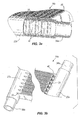
- each microchannel condenser coil 14a, 14b includes an inlet manifold 22a, 22b and an outlet manifold 26a, 26b fluidly connected by a plurality of flat tubes 30.
- the inlet manifold 22a, 22b includes an inlet port 34a, 34b for receiving refrigerant
- the outlet manifold 26a, 26b includes an outlet port 38a, 38b for discharging the refrigerant.
- One or more baffles may be placed in the inlet manifold 22a, 22b and/or the outlet manifold 26a, 26b to cause the refrigerant to make multiple passes through the flat tubes 30 for enhanced cooling of the refrigerant.
- the flat tubes 30 may be formed to include multiple internal passageways, or microchannels 42, that are much smaller in size than the internal passageway of the coil in a conventional fin-and-tube condenser coil.
- the microchannels 42 allow for more efficient heat transfer between the airflow passing over the flat tubes 30 and the refrigerant carried within the microchannels 42, compared to the airflow passing over the coil of the conventional fin-and-tube condenser coil.
- the microchannels 42 each are configured with a rectangular cross-section, although other constructions of the flat tubes 30 may have passageways of other cross-sections.
- the flat tubes 30 are separated into about 10 to 15 microchannels 42, with each microchannel 42 being about 1.5 mm in height and about 1.5 mm in width, compared to a diameter of about 9.5 mm (3/8") to 12.7 mm (1/2") for the internal passageway of a coil in a conventional fin-and-tube condenser coil.
- the microchannels 42 may be as small as 0.5 mm by 0.5 mm, or as large as 4 mm by 4 mm.
- the flat tubes 30 may also be made from extruded aluminum to enhance the heat transfer capabilities of the flat tubes 30.
- the flat tubes 30 are about 22 mm wide.
- the flat tubes 30 may be as wide as 26 mm, or as narrow as 18 mm.
- the spacing between adjacent flat tubes 30 may be about 9.5 mm.
- the spacing between adjacent flat tubes 30 may be as much as 16 mm, or as little as 3 mm.
- each microchannel condenser coil 14a, 14b includes a plurality of fins 46 coupled to and positioned along the flat tubes 30.
- the fins 46 are generally arranged in a zig-zag pattern between adjacent flat tubes 30.
- the fin density measured along the length of the flat tubes 30 is between 12 and 24 fins per inch.
- the fin density may be slightly less than 12 fins per inch or more than 24 fins per inch.
- the fins 46 aid in the heat transfer between the airflow passing through the microchannel condenser coils 14a, 14b and the refrigerant carried by the microchannels.
- the fins 46 may also include a plurality of louvers formed therein to provide additional heat transfer area.
- the increased efficiency of the microchannel condenser coils 14a, 14b is due in part to such a high fin density, compared to the fin density of 2 to 4 fins per inch of a conventional fin-and-tube condenser coil.
- microchannel condenser coils 14a, 14b compared to a conventional fin-and-tube condenser coil, allows the microchannel condenser coils 14a, 14b to be physically much smaller than the fin-and-tube condenser coil.
- the microchannel condenser coils 14a, 14b are not nearly as tall, and are not nearly as wide as a conventional fin-and-tube condenser coil.
- microchannel condenser coils 14a, 14b are attractive for use with large-scale refrigeration systems for these and other reasons. Since the microchannel condenser coils 14a, 14b are much smaller than conventional fin-and-tube condenser coils, the microchannel condenser coils 14a, 14b may occupy less space on the rooftops of the retail stores in which they are installed. As a result, the microchannel condenser coils 14a, 14b are more aesthetically appealing from an outside perspective of the store.
- the microchannel condenser coils 14a, 14b are much smaller than conventional fin-and-tube condenser coils, the microchannel condenser coils 14a, 14b may also contain less refrigerant compared to the conventional fin-and-tube condenser coils. Further, less refrigerant may be required to be contained within the entire refrigeration system, therefore effectively decreasing potential damage to the environment by an accidental atmospheric release. Also, as a result of being able to decrease the amount of refrigerant in the refrigeration system, the retail stores may see an energy savings, since the compressor(s) may expend less energy to compress the decreased amount of refrigerant in the refrigeration system.
- the condenser assembly 10 also includes fans 50 coupled to the microchannel condenser coils 14a, 14b to provide an airflow through the coils 14a, 14b.
- each microchannel condenser coil 14a, 14b includes two fans 50 mounted thereon.
- centrifugal blowers may be used in place of the fans 50 or in combination with the fans 50.
- the fans 50 are supported in a fan shroud 54, which guides the airflow generated by the fans 50 through the microchannel condenser coils 14a, 14b, and helps distribute the airflow amongst the face of each condenser coil 14a, 14b.
- the fans 50 may be "low-noise" fans, like the SWEPTWING TM fans available from Revcor, Inc. of Carpentersville, IL. to help decrease noise emissions from the condenser assembly 10.
- more or less than two fans 50 may be used for each condenser coil 14a, 14b to generate the airflow through the condenser coil 14a, 14b.
- the fans 50 and/or the shroud 54 may comprise any number of designs different than that shown in FIGS. 1-2.
- FIG. 2 illustrates the shroud 54 supporting an electric motor 58 for driving one of the fans 50.
- the electric motor 58 may be configured to operate using either an AC or DC power source. Further, the electric motor 58 may be electrically connected to a controller (not shown) that selectively activates the electric motor 58 to drive the fan 50 depending on any number of conditions monitored by the controller. For example, the fans 50 may be cycled on and off to either increase or decrease the heat transfer capability of the condenser coils 14a, 14b. In one manner of operating the fans 50, the fans 50 may be turned off during the nighttime, when the ambient temperature around the condenser assembly 10 is typically less than during the daytime.
- the controller may receive a signal from a pressure sensor that is in communication with one or both of the condenser coils 14a, 14b that is proportional to the pressure in the coils 14a, 14b.
- a measured pressure greater than some pre-determined threshold pressure may trigger the controller to activate the electric motors 58 to drive the fans 50 to provide additional heat transfer capability to the coils 14a, 14b.
- a measured pressure less than some pre-determined threshold pressure may trigger the controller to deactivate the electric motors 58 to stop the fans 50.
- FIG. 1 illustrates two microchannel condenser coils 14a, 14b fluidly connected with the refrigeration system in a series arrangement.
- the inlet port 34a of a first microchannel condenser coil 14a is shown coupled to an inlet header 59, whereby compressed, gaseous refrigerant is pumped to the first microchannel condenser coil 14a via the inlet header 59.
- the inlet header 59 is coupled to the inlet pont 34a by a brazing or welding process.
- Such a brazing or welding process provides a substantially fluid-tight connection between the inlet header 59 and the inlet port 34a.
- other constructions of the condenser assembly 10 may utilize some sort of fluid-tight releasable couplings to allow serviceability of the coils 14a, 14b.
- the outlet port 38a of the first microchannel condenser coil 14a is shown coupled to an inlet port 34b of a second microchannel condenser coil 14b via a connecting conduit 60.
- the outlet port 38a of the first microchannel condenser coil 14a is coupled to the connecting conduit 60 by a brazing or welding process
- the inlet port 34b of the second microchannel condenser coil 14b is also coupled the connecting conduit 60 by a brazing or welding process.
- a brazing or welding process provides a substantially fluid-tight connection between the outlet port 38a of the first microchannel condenser coil 14a and the inlet port 34b of the second microchannel condenser coil 14b.
- other constructions of the condenser assembly 10 may utilize some sort of permanent or releasable fluid-tight couplings.
- the outlet port 38b of the second microchannel condenser coil 14b is shown coupled to an outlet header 61, whereby compressed, substantially liquefied refrigerant is discharged from the second microchannel condenser coil 14b to the outlet header 61 for transporting the liquid refrigerant to a receiver (not shown) or other component in the refrigeration system.
- the outlet port 38b of the second microchannel condenser coil 14b is coupled to the outlet header 61 by a brazing or welding process to provide a substantially fluid-tight connection between the outlet port 38b of the second microchannel condenser coil 14b and the outlet header 61.
- other constructions of the condenser assembly 10 may utilize some sort of permanent or releasable fluid-tight couplings.
- the compressed, gaseous refrigerant is pumped into the first microchannel condenser coil 14a, where the heat transfer between the airflow passing through the condenser coil 14a and the refrigerant causes the gaseous refrigerant to at least partially condense as the refrigerant passes through the flat tubes 30. If baffles are not placed in either of the inlet or outlet manifolds 22a, 26a of the first microchannel condenser coil 14a, the refrigerant will make one pass from the inlet manifold 22a to the outlet manifold 26a before being discharged from the first microchannel condenser coil 14a. Further, the fans 50 may be activated to provide and/or enhance the airflow through the first microchannel condenser coil 14a to further enhance cooling of the refrigerant.
- the refrigerant is passed from the first microchannel condenser coil 14a to the second microchannel condenser coil 14b. If only a portion of the compressed, gaseous refrigerant is condensed in the first microchannel condenser coil 14a, then the remaining portion is condensed in the second microchannel condenser coil 14b.
- the refrigerant will make one pass from the 5 inlet manifold 22b to the outlet manifold 26b before being discharged from the second microchannel condenser coil 14b.
- the fans 50 may be activated to provide and/or enhance the airflow through the second microchannel condenser coil 14b to further enhance cooling of the refrigerant.
- FIG. 4 illustrates a condenser assembly 62 having two microchannel condenser coils ) 64a, 64b fluidly connected with the refrigeration system in a parallel arrangement.
- the frame 18 illustrated in FIG. 4 is substantially the same as that shown in FIG.1, the particular design of which is for illustrative purposes only and will not be further discussed.
- the fans 50 and the fan shrouds 54 are also substantially the same as that shown in FIG.1, and will not be further discussed.
- Inlet ports 66a, 66b of the first and second microchannel condenser coils 64a, 64b are shown extending from inlet manifolds 70a, 70b and coupled to an inlet header 74, whereby compressed, gaseous refrigerant is pumped to the first and second microchannel condenser coils 64a, 64b via the inlet header 74.
- the inlet header 74 is coupled to the inlet ports 66a, 66b of the first and second microchannel condenser coils 64a, 64b by a brazing or welding process to provide a substantially fluid-tight connection between the inlet header 74 and the inlet ports 66a, 66b.
- other constructions of the condenser assembly 62 may utilize some sort of permanent or releasable fluid-tight couplings.
- "orifice buttoning" may be used in the condenser assembly 62 to facilitate a substantially equal distribution of refrigerant to the coils 64a, 64b along the inlet header 74. This may be accomplished by varying the flow space through the inlet ports 66a, 66b of the coils 64a, 64b. In the illustrated construction of FIG. 4, coil 64b is located downstream of coil 64a. Furthermore, to maintain a substantially similar flow rate of refrigerant through both of the coils 64a, 64b, the inlet port 66a of coil 64a may be smaller than the inlet port 66b of coil 64b to accommodate for the pressure drop between the coils 64a, 64b.
- Outlet ports 78a, 78b of the first and second microchannel condenser coils 64a, 64b are shown extending from outlet manifolds 82a, 82b coupled to an outlet header 86, whereby compressed, liquid refrigerant is discharged from the first and second microchannel condenser coils 64a, 64b via the outlet header 86.
- the outlet header 86 is coupled to the outlet ports 78a, 78b of the first and second microchannel condenser coils 64a, 64b by a brazing or welding process to provide a substantially fluid-tight connection between the outlet header 86 and the outlet ports 78a, 78b.
- other constructions of the condenser assembly 62 may utilize some sort of permanent or releasable fluid-tight couplings.
- the outlet header 86 may be configured to be used as a receiver for the liquid refrigerant condensed by the microchannel condenser coils 64a, 64b (see FIG. 10).
- the receiver is typically sized to be able to hold all of the refrigerant in the system in a condensed form.
- One or more liquid refrigerant lines may therefore fluidly connect the receiver and the one or more evaporators in the refrigeration system.
- a dedicated separate receiver tank (not shown) is not required in the refrigeration system. This allows a sizable component, in addition to the piping associated therewith, to be eliminated from the refrigeration system. Additional benefits such as those outlined above may be realized by reducing the amount of refrigerant in the refrigeration system.
- the inlet ports 66a, 66b extend substantially transversely from the inlet manifolds 70a, 70b, and the outlet ports 78a, 78b extend substantially transversely from the outlet manifolds 82a, 82b to fluidly connect with the inlet and outlet headers 74, 86.
- the inlet ports 66a, 66b and the outlet ports 78a, 78b may extend from the respective inlet manifolds 70a, 70b and the outlet manifolds 82a, 82b as shown in FIG. 1, and utilize additional intermediate piping to fluidly connect the inlet ports 66a, 66b with the inlet header 74 and the outlet ports 78a, 78b with the outlet header 86.
- the compressed, gaseous refrigerant is pumped through the inlet header 74, where the some of the gaseous refrigerant enters the first microchannel condenser coil 64a and the remaining gaseous refrigerant enters the second microchannel condenser coil 64b.
- Heat transfer between the airflow passing through the condenser coils 64a, 64b and the refrigerant causes the gaseous refrigerant to condense as the refrigerant passes through the flat tubes 30.
- the refrigerant will make one pass from the inlet manifold 70a to the outlet manifold 82a before being discharged from the first microchannel condenser coil 64a to the outlet header 86.
- the fans 50 may be activated to provide and/or enhance the airflow through the first microchannel condenser coil 64a to further enhance cooling of the refrigerant.
- the condenser coils 64a, 64b are connected with the refrigeration system in a parallel arrangement, and if baffles are not placed in either of the inlet manifold 70b or the outlet manifold 82b of the second microchannel condenser coil 64b, the refrigerant will make one pass from the inlet manifold 70b to the outlet manifold 82b before being discharged from the second microchannel condenser coil 64b to the outlet header 86, where the liquid refrigerant rejoins the liquid refrigerant discharged by the first microchannel condenser coil 64a.
- the fans 50 may be activated to provide and/or enhance the airflow through the second microchannel condenser coil 64b to further enhance cooling of the refrigerant.
- Each microchannel condenser coil 64a, 64b may also include multiple inlet and outlet ports (not shown), corresponding with multiple baffles (not shown) located within the inlet manifolds 70a, 70b and/or the outlet manifolds 82a, 82b to provide multiple cooling circuits throughout each microchannel condenser coil 64a, 64b.
- the condenser assembly 10 or 62 may also include a compressor 90 coupled thereto to yield a condenser unit 94 (see FIG. 5).
- the compressor 90 may be coupled to the frame 18 of the condenser assembly 10 or 62 by any of a number of conventional methods, and may be fluidly connected with the microchannel condenser coils 14a, 14b, 64a, 64b to provide the compressed, gaseous refrigerant to the coils 14a, 14b, 64a, 64b.
- the compressor is located in a machine room separate from the retail area of the retail store.
- the compressor in the machine room is typically remotely located from the rest of the components in the refrigeration system, including the evaporators, which are typically located within refrigerated merchandisers (not shown) in the retail area of the store, and the condensers, which are typically located on the rooftop of the retail store.
- the compressor 90 By placing the compressor 90 with the condenser assembly 10 or 62, the amount of piping and conduit required to fluidly connect the compressor 90 with the microchannel condenser coils 14a, 14b, 64a, 64b may be decreased. Subsequently, the amount of refrigerant that is carried in the system may also be decreased.
- the microchannel condenser coils 14a, 14b, 64a, 64b allow for a unique method of assembling the condenser assemblies 10, 62.
- a single, large conventional fin-and-tube condenser coil is typically provided in a retail store refrigeration system to condense all of the refrigerant in the refrigeration system.
- This conventional fin-and-tube condenser coil must be appropriately sized to accommodate the heat load of the refrigeration system.
- the conventional fin-and-tube condenser coil must be large enough to dissipate the heat in the gaseous refrigerant for the entire system.
- Such a condenser coil must often be custom manufactured to the size required by the refrigeration system.
- frame and fan shrouds may also require custom manufacturing to match up with the custom manufactured conventional fin and tube condenser coil. This may drive up the costs associated with manufacturing a condenser assembly utilizing a conventional fin-and-tube condenser coil.
- microchannel condenser coils 14a, 14b, 64a, 64b are manufactured in standard sizes, which allows the manufacturer of the condenser assembly 10 or 62 to utilize their expertise to calculate the total heat load of a particular refrigeration system and determine how many standard-sized microchannel condenser coils 14a, 14b or 64a, 64b will be required to satisfy the total heat load of the refrigeration system. After determining how many standard-sized microchannel condenser coils14a, 14b or 64a, 64b will be required, the manufacturer may utilize their capabilities to put together the condenser assembly 10 or 62.
- Fluid connections may be made by brazing or welding processes, or releasable couplings may be used to allow serviceability of the coils 14a, 14b or 64a, 64b.
- the fans 50 and the fan shrouds 54 may be manufactured or purchased by the condenser assembly manufacturer in standard sizes to match up with the standard-sized microchannel condenser coils 14a, 14b, 64a, 64b.
- the frame 18 may be either custom made to support multiple connected microchannel condenser coils 14a, 14b or 64a, 64b, or the frame 18 may be standard-sized to support a single or dual microchannel condenser coils 14a, 14b or 64a, 64b, for example. This method of assembling the condenser assemblies 10, 62 may allow the manufacturer to streamline their operation, which in turn may result in decreased costs for the manufacturer.
- microchannel condenser coils 14a, 14b or 64a, 64b are shown in the illustrated constructions of FIGS. 1 and 4, more or less than two microchannel condenser coils 14a, 14b or 64a, 64b may be included in the condenser assemblies 10 or 62 to satisfy the total heat load of the refrigeration system in which the microchannel condenser coils 14a, 14b or 64a, 64b will be used.
- FIG. 6a illustrates a microchannel condenser coil 98 substantially similar to the coils 14a, 14b, 64a, 64b with the exception that the coil 98 includes multiple inlet ports 102 and outlet ports 106.
- This style of microchannel condenser coil 98 may provide a better distribution of vaporized refrigerant to an inlet manifold 110 of the coil 98, in addition to a better distribution of liquid refrigerant from an outlet manifold 114 of the coil 98.
- FIG. 6b illustrates another microchannel condenser coil 118 substantially similar to the coils 14a, 14b, 64a, 64b, 98 with the exception that the coil 118 is divided into two separate and distinct fluid circuits by a baffle 122 positioned in an inlet manifold 126 of the coil 118 and another baffle 130 positioned in an outlet manifold 134 of the coil 118.
- This style of microchannel condenser coil 118 may allow refrigerant from multiple refrigeration circuits (corresponding with multiple refrigeration display cases) to be passed through the coil 118.
- benefits such as a reduction in the number of separate and dedicated condenser coils for each refrigeration circuit may be achieved by using the coil 118 of FIG. 6b. Subsequently, the amount of refrigerant that is carried in each refrigeration circuit may also be reduced.
- any of the microchannel condenser coils 14a, 14b, 64a, 64b, 98, or 118 may be grouped together in either single-row assemblies or multiple-row assemblies.
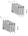
- FIGS. 7a and 7b illustrate coils being grouped in multiple-row assemblies 138, 142, respectively.
- FIGS. 7a and 7b illustrate coils being grouped in three-row assemblies 138, 142.
- the coils are stacked one on top of another such that airflow is directed through all of the coils.
- three coils are shown in the multiple-row assemblies 138, 142 of FIGS.
- FIGS. 7a and 7b generally illustrate the coils 14a, 14b, it should be known that any of the coils 14a, 14b, 64a, 64b, 98, or 118 may be used in forming the assemblies 138,142.
- the three coils in the assembly 138 are shown in a fluid series connection, whereby refrigerant is passed through the three coils one after another.
- the three coils in the assembly 142 are shown in a fluid parallel connection, whereby refrigerant is passed through the coils independently of one another.
- it is up to the manufacturer to determine if multiple-row assemblies 138, 142 will be used.
- multiple-row assemblies 138, 142 are to be used, it is up to the manufacturer to determine whether to use an assembly 138 having coils grouped in a fluid series connection, or an assembly 142 having coils grouped in a fluid parallel connection.
- FIGS. 8a and 8b illustrate coils being grouped in single-row assemblies 146, 150.
- FIGS. 8a and 8b illustrate the coils being grouped in a single-row assembly 146 of three coils.
- the coils are unfolded, or spread out such that airflow passing through one of the coils is not directed through another of the three coils.
- three coils are shown in the single-row assemblies 146, 150 of FIGS. 8a and 8b, more or less than three coils may be used depending on the total heat load of the particular refrigeration system in which the assemblies 146, 150 are used.
- FIGS. 8a and 8b generally illustrate the coils 14a, 14b, it should be known that any of the coils 14a, 14b, 64a, 64b, 98, or 118 may be used in forming the assemblies 146, 150.
- the three coils in the assembly 146 are shown in a fluid series connection, whereby refrigerant is passed through the three coils one after another.
- the three coils in the assembly 150 are shown in a fluid parallel connection, whereby refrigerant is passed through the coils independently of one another.
- it is up to the manufacturer to determine if single-row assemblies 146, 150 will be used.
- single-row assemblies 146, 150 are to be used, it is up to the manufacturer to determine whether to use an assembly 146 having coils grouped in a fluid series connection, or an assembly 150 having coils grouped in a fluid parallel connection.
- one or more assemblies 138, 142, 146, or 150 may be grouped into a series configuration 154 or a parallel configuration 158 with an inlet header 162 and an outlet header 166.
- a three-row assembly 138 and a single row assembly 146 are grouped into a fluid series configuration 154 between the inlet header 162 and the outlet header 166.
- the three-row assembly 138 and single-row assembly 146 are shown in the series configuration 154 of FIG. 9a, any combination of multiple-row assemblies 138 or 142 and single-row assemblies 146 or 150 may be used depending on the determination of the manufacturer.
- FIG. 9a generally illustrates the coils 14a, 14b, it should be known that any of the coils 14a, 14b, 64a, 64b, 98, or 118 may be used in forming the assemblies 138, 142, 146, or 150 that comprise either the series configuration 154 or the parallel configuration 158.
- a three-row assembly 138 and a single row assembly 146 are grouped into a fluid parallel configuration 158 between the inlet header 162 and the outlet header 166.
- the three-row assembly 138 and the single-row assembly 146 are shown in the parallel configuration 158 of FIG. 9b, any combination of multiple-row assemblies 138 or 142 and single-row assemblies 146 or 150 may be used depending on the ) determination of the manufacturer.
- more or less than two assemblies 138, 142, 146, or 150 may be used in the parallel configuration 158 depending on the total heat load of the particular refrigeration system in which the parallel configuration 158 is used.
- FIG. 9a generally illustrates the coils 14a, 14b, it should be known that any of the coils 14a, 14b, 64a, 64b, 98, or 118 may be used in forming the assemblies 138, 142, 146, or 150 that comprise either the series configuration 154 or the parallel configuration 158. Further, one or more baffles (not shown) may be positioned in the inlet and outlet headers 162, 166 between adjacent assemblies 138, 142, 146, or 150 to divide the configuration 154 or 158 into multiple fluid circuits.
- FIG. 1 illustrates a single-row assembly 146 in a series configuration 154 between the inlet header 59 and the outlet header 61, whereby the coils 14a, 14b in the single-row assembly 146 are grouped into a fluid series connection.
- FIG. 4 illustrates a single-row assembly 150 in a parallel configuration 158 between the inlet header 74 and the outlet header 86, whereby the coils 64a, 64b in the single-row assembly 150 are grouped into a fluid parallel connection.
- FIG. 10 illustrates a third construction of a condenser assembly 170 including three two-row assemblies 138 in a parallel configuration 158 between an inlet header 174 and an outlet header 178.
- Each two-row assembly 138 includes two microchannel condenser coils 14a, 14b grouped in a fluid series connection. Rather than being permanently connected to the inlet and outlet headers 174, 178, respectively, the coils 14a, 14b may be coupled to the inlet and outlet headers 174, 178 by fluid-tight releasable couplings 182.
- the couplings 182 are illustrated in FIG. 10, and may comprise any known suitable fluid-tight, quick-release coupling and/or releasable coupling.
- the assemblies 138 are permitted to be removed and/or replaced to accommodate a varying heat load or to permit serviceability of a damaged assembly 138.
- the condenser assembly 170 also includes an oversized outlet header 178 that also acts as a receiver for the liquid refrigerant discharged from the coils 14a, 14b.
- One or more liquid refrigerant outlets 186 may extend from the oversized outlet header 178 to distribute the liquid refrigerant to the one or more evaporators in the refrigeration system.
- FIG. 11 illustrates a fourth construction of a condenser assembly 190 including a two-row assembly 138, with three separate and distinct fluid circuits, in a parallel configuration 158 between multiple inlet headers 194 and multiple outlet headers 198.
- the two-row assembly 138 includes two microchannel condenser coils 118 grouped in a fluid series connection. As previously explained, the coils 118 each include respective baffles 122, 130 in the inlet and outlet manifolds 126, 134 to establish separate and distinct fluid circuits through the assembly 138.
- the assembly 138 of FIG. 11 may utilize fluid-tight couplings 182 to permit removal and/or replacement of the assembly 138 to accommodate a varying heat load or to permit serviceability of a damaged assembly 138.
- FIG. 12 illustrates a fifth construction of a condenser assembly 202 including a single-row assembly 150 between an inlet header 206 and an outlet header 210.
- the single-row assembly 150 includes four microchannel condenser coils 64a, 64b grouped in a fluid parallel connection.
- the coils 64a, 64b are inclined with respect to the inlet and outlet headers 206, 210, such that the footprint of the condenser assembly 202 is reduced (compared to the assembly 62 of FIG. 4, for example).
- FIG. 12 generally illustrates the coils 64a, 64b, it should be known that any of the coils 14a, 14b, 64a, 64b, 98, or 118 may be used in forming the assembly 150.
- the condenser assemblies 10, 62, 170, 190, 202 can be relatively small or relatively large. If a relatively large heat load must be satisfied, a relatively large condenser assembly (such as the assembly 170 of FIG. 10) having a plurality of assemblies 138, 142, 146, or 150 may be used. However, if a relatively small heat load must be satisfied, a relatively small condenser assembly (such as the assemblies 10, 62 of FIGS. 1 and 4, respectively) having only one assembly 138, 142, 146, 150 may be used.
- the condenser assemblies 10, 62, 170, 190, 202 are shown for exemplary reasons only, and are not meant to limit the spirit and/or scope of the present invention.
Landscapes
- Engineering & Computer Science (AREA)
- Mechanical Engineering (AREA)
- General Engineering & Computer Science (AREA)
- Physics & Mathematics (AREA)
- Thermal Sciences (AREA)
- Heat-Exchange Devices With Radiators And Conduit Assemblies (AREA)
- Devices That Are Associated With Refrigeration Equipment (AREA)
- Air-Conditioning For Vehicles (AREA)
Applications Claiming Priority (2)
| Application Number | Priority Date | Filing Date | Title |
|---|---|---|---|
| US762416 | 1991-09-19 | ||
| US10/762,416 US6988538B2 (en) | 2004-01-22 | 2004-01-22 | Microchannel condenser assembly |
Publications (3)
| Publication Number | Publication Date |
|---|---|
| EP1557622A2 true EP1557622A2 (de) | 2005-07-27 |
| EP1557622A3 EP1557622A3 (de) | 2006-12-20 |
| EP1557622B1 EP1557622B1 (de) | 2018-08-22 |
Family
ID=34634595
Family Applications (1)
| Application Number | Title | Priority Date | Filing Date |
|---|---|---|---|
| EP05250232.5A Revoked EP1557622B1 (de) | 2004-01-22 | 2005-01-18 | Mikrokanal-Verflüssiger |
Country Status (3)
| Country | Link |
|---|---|
| US (1) | US6988538B2 (de) |
| EP (1) | EP1557622B1 (de) |
| ES (1) | ES2695574T3 (de) |
Cited By (23)
| Publication number | Priority date | Publication date | Assignee | Title |
|---|---|---|---|---|
| WO2007037670A1 (en) * | 2005-09-30 | 2007-04-05 | Seasonair (M) Sdn Bhd | Heat exchanger |
| DE102007023696A1 (de) | 2007-05-22 | 2008-11-27 | Institut für Luft- und Kältetechnik gGmbH | Verflüssiger für Haushaltskältegeräte |
| DE102007023673A1 (de) | 2007-05-22 | 2008-11-27 | Institut für Luft- und Kältetechnik gGmbH | Rückwandverflüssiger für Haushaltskältegeräte |
| WO2009007168A1 (de) * | 2007-07-09 | 2009-01-15 | A-Heat Allied Heat Exchange Technology Ag | Wärmeaustauschsystem mit einem wärmetauscher, sowie ein verfahren zur herstellung eines wärmeaustauschsystems |
| WO2010000311A1 (de) * | 2008-07-01 | 2010-01-07 | A-Heat Allied Heat Exchange Technology Ag | Wärmetauscherblock, sowie ein verfahren zur herstellung eines wärmetauscherblocks |
| WO2010040635A1 (de) * | 2008-10-08 | 2010-04-15 | A-Heat Allied Heat Exchange Technology Ag | Wärmetauscheranordnung und verfahren zum betrieb derselben |
| FR2952172A1 (fr) * | 2009-11-03 | 2011-05-06 | Peugeot Citroen Automobiles Sa | Condenseur de circuit de refrigeration a encombrement vertical reduit |
| FR2952173A1 (fr) * | 2009-11-03 | 2011-05-06 | Peugeot Citroen Automobiles Sa | Condenseur de circuit de refrigeration a encombrement vertical reduit par subdivision en unites alignees suivant une direction longitudinale |
| WO2011134786A1 (de) | 2010-04-29 | 2011-11-03 | A-Heat Allied Heat Exchange Technology Ag | Wärmeaustauscheranordnung |
| CN102243026A (zh) * | 2010-05-11 | 2011-11-16 | 王庆鹏 | 微孔式空气换热器结构及典型采暖空调应用形式 |
| WO2011084364A3 (en) * | 2009-12-16 | 2011-11-24 | Lennox International, Inc. | Microchannel coil manifold system |
| WO2011006771A3 (de) * | 2009-07-14 | 2011-11-24 | Behr Industry Gmbh & Co. Kg | Wärmetauscher |
| ITMI20101395A1 (it) * | 2010-07-28 | 2012-01-29 | Ansaldo Energia Spa | Metodo per il controllo di un condensatore ad aria di un impianto per la produzione di energia elettrica con selezione automatica dello stato e impianto per la produzione di energia elettrica |
| EP1757891A3 (de) * | 2005-08-27 | 2012-03-07 | Behr GmbH & Co. KG | Wärmeübertrager, insbesondere Kühlmittelkühler für Kraftfahrzeuge |
| WO2013051037A1 (en) * | 2011-10-03 | 2013-04-11 | Fbm Hudson Italiana | Header for air -liquid heat exchanger with lateral inlet and outlet gates of the process fluid |
| US9546804B2 (en) | 2009-12-16 | 2017-01-17 | Heatcraft Refrigeration Products Llc | Microchannel coil spray system |
| EP2502002B1 (de) * | 2009-11-19 | 2018-02-21 | Hobart Brothers LLC | Kondensatoranordnungen für heiz-, belüftungs-, klimatisierungs- und kühlsysteme |
| RU2684357C1 (ru) * | 2018-04-03 | 2019-04-08 | Общество с ограниченной ответственностью "Элементум. Надежное оборудование" | Теплообменный аппарат |
| US10264713B2 (en) | 2016-08-19 | 2019-04-16 | Dell Products, Lp | Liquid cooling system with extended microchannel and method therefor |
| EP2079969B1 (de) * | 2006-10-13 | 2020-01-22 | Carrier Corporation | Kühlkreislauf |
| FR3095502A1 (fr) * | 2019-04-29 | 2020-10-30 | Valeo Systemes Thermiques | Dispositif d’échange thermique modulable |
| IT201900025159A1 (it) * | 2019-12-20 | 2021-06-20 | Friulair S R L | Apparato di condizionamento |
| WO2022219098A1 (en) * | 2021-04-13 | 2022-10-20 | Urban Cooling Limited | Condenser assembly |
Families Citing this family (48)
| Publication number | Priority date | Publication date | Assignee | Title |
|---|---|---|---|---|
| US7281387B2 (en) | 2004-04-29 | 2007-10-16 | Carrier Commercial Refrigeration Inc. | Foul-resistant condenser using microchannel tubing |
| DE602005024349D1 (de) * | 2004-09-30 | 2010-12-09 | Nissan Motor | Verfahren und Vorrichtung zur Verbrennungssteuerung einer direkteinspritzenden Brennkraftmaschine mit Fremdzündung |
| US20060130517A1 (en) * | 2004-12-22 | 2006-06-22 | Hussmann Corporation | Microchannnel evaporator assembly |
| US20080083237A1 (en) * | 2006-10-06 | 2008-04-10 | Hussmann Corporation | Electronic head pressure control |
| WO2008064238A1 (en) * | 2006-11-22 | 2008-05-29 | Johnson Controls Technology Company | Multichannel heat exchanger with dissimilar multichannel tubes |
| WO2008064228A1 (en) * | 2006-11-22 | 2008-05-29 | Johnson Controls Technology Company | Multichannel evaporator with flow mixing microchannel tubes |
| WO2008064247A1 (en) * | 2006-11-22 | 2008-05-29 | Johnson Controls Technology Company | Multi-function multichannel heat exchanger |
| US20080216493A1 (en) * | 2007-03-08 | 2008-09-11 | Liebert Corporation | Microchannel cooling condenser for precision cooling applications |
| CN101680690B (zh) * | 2007-05-22 | 2014-05-28 | 通风及制冷技术有限公司研究所 | 用于家用制冷装置的设在后壁上的制冷器 |
| US8166776B2 (en) * | 2007-07-27 | 2012-05-01 | Johnson Controls Technology Company | Multichannel heat exchanger |
| US20090025405A1 (en) * | 2007-07-27 | 2009-01-29 | Johnson Controls Technology Company | Economized Vapor Compression Circuit |
| EP2193315B1 (de) * | 2007-08-24 | 2011-10-12 | Johnson Controls Technology Company | Dampfkompressionsanlage und steuerungsverfahren dafür |
| US20090084131A1 (en) * | 2007-10-01 | 2009-04-02 | Nordyne Inc. | Air Conditioning Units with Modular Heat Exchangers, Inventories, Buildings, and Methods |
| US8047555B2 (en) * | 2007-10-31 | 2011-11-01 | Illinois Tool Works Inc. | Airplane ground support equipment cart having extractable modules and a generator module that is seperable from power conversion and air conditioning modules |
| US8037714B2 (en) * | 2007-10-31 | 2011-10-18 | Illinois Tool Works Inc. | Adjustable air conditioning control system for a universal airplane ground support equipment cart |
| US8055388B2 (en) * | 2007-10-31 | 2011-11-08 | Illinois Tool Works Inc. | Maintenance and control system for ground support equipment |
| US8117864B2 (en) * | 2007-10-31 | 2012-02-21 | Illinois Tool Works Inc. | Compact, modularized air conditioning system that can be mounted upon an airplane ground support equipment cart |
| CA2709638A1 (en) * | 2007-12-18 | 2009-06-25 | A-Heat Allied Heat Exchange Technology Ag | Heat exchange system |
| EP2235467A4 (de) * | 2007-12-18 | 2013-10-23 | Carrier Corp | Wärmetauscher zum abstossen von wasser |
| US8347503B2 (en) * | 2008-06-30 | 2013-01-08 | Uop Llc | Methods of manufacturing brazed aluminum heat exchangers |
| US20110056667A1 (en) * | 2008-07-15 | 2011-03-10 | Taras Michael F | Integrated multi-circuit microchannel heat exchanger |
| US9091451B2 (en) * | 2009-06-05 | 2015-07-28 | Hobart Brothers Company | Modular heating, ventilating, air conditioning, and refrigeration systems and methods |
| IN2012DN02774A (de) * | 2009-11-03 | 2015-09-18 | Carrier Corp | |
| US9062887B2 (en) * | 2009-11-19 | 2015-06-23 | Hobart Brothers Company | Modular heating, ventilating, air conditioning, and refrigeration systems and methods |
| US20110139410A1 (en) * | 2009-12-16 | 2011-06-16 | Lennox International, Inc. | Floating Coil Heat Exchanger |
| US8899057B2 (en) | 2010-09-17 | 2014-12-02 | Hobart Brothers Company | Control systems and methods for modular heating, ventilating, air conditioning, and refrigeration systems |
| US10145601B2 (en) * | 2011-12-19 | 2018-12-04 | Mitsubishi Electric Corporation | Outdoor unit and refrigeration cycle apparatus including the outdoor unit |
| US20140202669A1 (en) * | 2013-01-21 | 2014-07-24 | Denso International America, Inc. | Dual radiator engine cooling module - single coolant loop |
| MX384404B (es) * | 2014-07-02 | 2025-03-14 | Evapco Inc | Sistema de refrigeración tipo paquete de baja carga |
| US10168083B2 (en) * | 2014-07-11 | 2019-01-01 | Hangzhou Sanhua Research Institute Co., Ltd. | Refrigeration system and heat exchanger thereof |
| KR101754665B1 (ko) * | 2015-06-02 | 2017-07-10 | (주)케이에프 | 백연 가스 저감 장치 |
| EP3358287B1 (de) * | 2015-09-30 | 2019-08-28 | Mitsubishi Electric Corporation | Wärmetauscher und damit ausgestattete kältekreislaufvorrichtung |
| US10323868B2 (en) | 2016-02-08 | 2019-06-18 | Trane International Inc. | Multi-coil microchannel evaporator |
| US11486646B2 (en) * | 2016-05-25 | 2022-11-01 | Spg Dry Cooling Belgium | Air-cooled condenser apparatus and method |
| US11839062B2 (en) | 2016-08-02 | 2023-12-05 | Munters Corporation | Active/passive cooling system |
| US11255611B2 (en) * | 2016-08-02 | 2022-02-22 | Munters Corporation | Active/passive cooling system |
| US10677492B2 (en) * | 2017-06-26 | 2020-06-09 | Therma-Stor, Llc | Portable stackable dehumidifier |
| US10619877B2 (en) * | 2017-06-26 | 2020-04-14 | Therma-Stor LLC | Control panel for a portable dehumidifier |
| US20190162455A1 (en) * | 2017-11-29 | 2019-05-30 | Lennox Industries, Inc. | Microchannel heat exchanger |
| US11226110B2 (en) * | 2018-01-29 | 2022-01-18 | Therma-Stor LLC | In-wall dehumidifier |
| US10788267B2 (en) * | 2018-06-25 | 2020-09-29 | General Electric Company | Condenser system, and condensate vessel assembly for power plant |
| US11679339B2 (en) * | 2018-08-02 | 2023-06-20 | Plug Power Inc. | High-output atmospheric water generator |
| US11415346B2 (en) | 2020-04-30 | 2022-08-16 | Trane International Inc. | System and method for common side connections for oversized multislab microchannel heat exchanger |
| US11835305B2 (en) * | 2020-07-02 | 2023-12-05 | Fang-Shou LEE | Openable and closeable condensing apparatus |
| TWI805943B (zh) * | 2020-09-09 | 2023-06-21 | 萬在工業股份有限公司 | 堆疊式垂直散熱裝置 |
| US12078431B2 (en) | 2020-10-23 | 2024-09-03 | Carrier Corporation | Microchannel heat exchanger for a furnace |
| WO2024069861A1 (ja) * | 2022-09-29 | 2024-04-04 | 日本電気株式会社 | 熱交換装置および冷却装置 |
| WO2024069869A1 (ja) * | 2022-09-29 | 2024-04-04 | 日本電気株式会社 | 熱交換装置および冷却装置 |
Family Cites Families (30)
| Publication number | Priority date | Publication date | Assignee | Title |
|---|---|---|---|---|
| US35655A (en) * | 1862-06-17 | Improvement in lamps | ||
| US1908463A (en) * | 1932-06-22 | 1933-05-09 | Carbondale Machine Company | Condenser |
| US2124291A (en) | 1935-04-01 | 1938-07-19 | Walter L Fleisher | Method of air conditioning |
| DE1205563B (de) | 1962-09-07 | 1965-11-25 | Gea Luftkuehler Happel Gmbh | Luftgekuehlter Oberflaechenkondensator |
| US3384165A (en) * | 1966-02-03 | 1968-05-21 | Du Pont | Heat exchanger |
| US3584866A (en) * | 1968-05-27 | 1971-06-15 | Ropak Mfg Co | Magnetic conveyor |
| US3584466A (en) | 1969-04-01 | 1971-06-15 | Elsters | Refrigerator-compressor system with wet weather adjustment |
| US3627037A (en) | 1970-04-27 | 1971-12-14 | Heat Fluid Engineering Corp | Factory-assembled heat exchanger |
| US3707185A (en) | 1971-03-25 | 1972-12-26 | Modine Mfg Co | Modular air cooled condenser |
| NL7206046A (de) | 1972-05-04 | 1973-11-06 | ||
| DE3219128A1 (de) | 1982-05-21 | 1983-11-24 | Thermal-Werke, Wärme-, Kälte-, Klimatechnik GmbH, 6909 Walldorf | Mehrkreislauf-verfluessiger |
| US4607497A (en) | 1983-12-20 | 1986-08-26 | Suetrak U.S.A. | Roof-mounted air conditioner system having modular evaporator and condensor units |
| WO1986000977A1 (en) | 1984-07-24 | 1986-02-13 | Conry Ronald D | Modular refrigeration system |
| US5279360A (en) * | 1985-10-02 | 1994-01-18 | Modine Manufacturing Co. | Evaporator or evaporator/condenser |
| US4998580A (en) | 1985-10-02 | 1991-03-12 | Modine Manufacturing Company | Condenser with small hydraulic diameter flow path |
| US5190100B1 (en) | 1986-07-29 | 1994-08-30 | Showa Aluminum Corp | Condenser for use in a car cooling system |
| DE3752324T2 (de) | 1986-07-29 | 2001-03-29 | Showa Aluminium Co Ltd | Kondensator |
| AU629811B2 (en) | 1988-01-19 | 1992-10-15 | Multistack International Pty. Ltd. | Improvements in heating and cooling systems |
| US5529116A (en) | 1989-08-23 | 1996-06-25 | Showa Aluminum Corporation | Duplex heat exchanger |
| US5138844A (en) | 1990-04-03 | 1992-08-18 | American Standard Inc. | Condenser fan control system for use with variable capacity compressor |
| US5121613A (en) * | 1991-01-08 | 1992-06-16 | Rheem Manufacturing Company | Compact modular refrigerant coil apparatus and associated manufacturing methods |
| US5067560A (en) * | 1991-02-11 | 1991-11-26 | American Standard Inc. | Condenser coil arrangement for refrigeration system |
| US6003592A (en) * | 1992-11-25 | 1999-12-21 | Denso Corporation | Refrigerant condenser |
| FR2716959B1 (fr) | 1994-03-04 | 1996-05-15 | Thermique Generale Vinicole | Ensemble de distribution et/ou collection de froid et/ou de chaud. |
| US5715889A (en) | 1996-05-06 | 1998-02-10 | Ardco, Inc. | Heat exchanger and the method for producing same |
| US5765393A (en) * | 1997-05-28 | 1998-06-16 | White Consolidated Industries, Inc. | Capillary tube incorporated into last pass of condenser |
| US6481216B2 (en) | 1999-09-22 | 2002-11-19 | The Coca Cola Company | Modular eutectic-based refrigeration system |
| US20020195240A1 (en) * | 2001-06-14 | 2002-12-26 | Kraay Michael L. | Condenser for air cooled chillers |
| US6557372B1 (en) | 2002-01-28 | 2003-05-06 | Smc Kabushiki Kaisha | Refrigerating unit having plural air cooled condensers |
| JP2003222351A (ja) | 2002-01-30 | 2003-08-08 | Daikin Ind Ltd | 空気熱交換ユニット |
-
2004
- 2004-01-22 US US10/762,416 patent/US6988538B2/en not_active Expired - Lifetime
-
2005
- 2005-01-18 ES ES05250232T patent/ES2695574T3/es not_active Expired - Lifetime
- 2005-01-18 EP EP05250232.5A patent/EP1557622B1/de not_active Revoked
Cited By (31)
| Publication number | Priority date | Publication date | Assignee | Title |
|---|---|---|---|---|
| EP1757891A3 (de) * | 2005-08-27 | 2012-03-07 | Behr GmbH & Co. KG | Wärmeübertrager, insbesondere Kühlmittelkühler für Kraftfahrzeuge |
| WO2007037670A1 (en) * | 2005-09-30 | 2007-04-05 | Seasonair (M) Sdn Bhd | Heat exchanger |
| EP2079969B1 (de) * | 2006-10-13 | 2020-01-22 | Carrier Corporation | Kühlkreislauf |
| DE102007023696A1 (de) | 2007-05-22 | 2008-11-27 | Institut für Luft- und Kältetechnik gGmbH | Verflüssiger für Haushaltskältegeräte |
| DE102007023673A1 (de) | 2007-05-22 | 2008-11-27 | Institut für Luft- und Kältetechnik gGmbH | Rückwandverflüssiger für Haushaltskältegeräte |
| DE102007023673B4 (de) * | 2007-05-22 | 2011-06-30 | Institut für Luft- und Kältetechnik gGmbH, 01309 | Rückwandverflüssiger für Haushaltskältegeräte |
| WO2009007168A1 (de) * | 2007-07-09 | 2009-01-15 | A-Heat Allied Heat Exchange Technology Ag | Wärmeaustauschsystem mit einem wärmetauscher, sowie ein verfahren zur herstellung eines wärmeaustauschsystems |
| JP2010532859A (ja) * | 2007-07-09 | 2010-10-14 | アー − ヒート アライド ヒート イクスチェンジ テクノロジー アクチェンゲゼルシャフト | 熱交換器を有する熱交換装置、および熱交換装置の製造方法 |
| WO2010000311A1 (de) * | 2008-07-01 | 2010-01-07 | A-Heat Allied Heat Exchange Technology Ag | Wärmetauscherblock, sowie ein verfahren zur herstellung eines wärmetauscherblocks |
| WO2010040635A1 (de) * | 2008-10-08 | 2010-04-15 | A-Heat Allied Heat Exchange Technology Ag | Wärmetauscheranordnung und verfahren zum betrieb derselben |
| WO2011006771A3 (de) * | 2009-07-14 | 2011-11-24 | Behr Industry Gmbh & Co. Kg | Wärmetauscher |
| FR2952173A1 (fr) * | 2009-11-03 | 2011-05-06 | Peugeot Citroen Automobiles Sa | Condenseur de circuit de refrigeration a encombrement vertical reduit par subdivision en unites alignees suivant une direction longitudinale |
| FR2952172A1 (fr) * | 2009-11-03 | 2011-05-06 | Peugeot Citroen Automobiles Sa | Condenseur de circuit de refrigeration a encombrement vertical reduit |
| EP2502002B1 (de) * | 2009-11-19 | 2018-02-21 | Hobart Brothers LLC | Kondensatoranordnungen für heiz-, belüftungs-, klimatisierungs- und kühlsysteme |
| WO2011084364A3 (en) * | 2009-12-16 | 2011-11-24 | Lennox International, Inc. | Microchannel coil manifold system |
| US9574827B2 (en) | 2009-12-16 | 2017-02-21 | Heatcraft Refrigeration Products Llc | Microchannel coil manifold system |
| US9546804B2 (en) | 2009-12-16 | 2017-01-17 | Heatcraft Refrigeration Products Llc | Microchannel coil spray system |
| WO2011134786A1 (de) | 2010-04-29 | 2011-11-03 | A-Heat Allied Heat Exchange Technology Ag | Wärmeaustauscheranordnung |
| CN102243026A (zh) * | 2010-05-11 | 2011-11-16 | 王庆鹏 | 微孔式空气换热器结构及典型采暖空调应用形式 |
| ITMI20101395A1 (it) * | 2010-07-28 | 2012-01-29 | Ansaldo Energia Spa | Metodo per il controllo di un condensatore ad aria di un impianto per la produzione di energia elettrica con selezione automatica dello stato e impianto per la produzione di energia elettrica |
| EP2413077A1 (de) * | 2010-07-28 | 2012-02-01 | Ansaldo Energia S.p.A. | Kontrollmethode für einen luftgekühlten Kondensator eines Stromkraftwerks mit automatischer Statusanpassung und Stromkraftwerk |
| WO2013051037A1 (en) * | 2011-10-03 | 2013-04-11 | Fbm Hudson Italiana | Header for air -liquid heat exchanger with lateral inlet and outlet gates of the process fluid |
| US10264713B2 (en) | 2016-08-19 | 2019-04-16 | Dell Products, Lp | Liquid cooling system with extended microchannel and method therefor |
| RU2684357C1 (ru) * | 2018-04-03 | 2019-04-08 | Общество с ограниченной ответственностью "Элементум. Надежное оборудование" | Теплообменный аппарат |
| FR3095502A1 (fr) * | 2019-04-29 | 2020-10-30 | Valeo Systemes Thermiques | Dispositif d’échange thermique modulable |
| WO2020221626A1 (fr) * | 2019-04-29 | 2020-11-05 | Valeo Systemes Thermiques | Dispositif d'échange thermique modulable |
| IT201900025159A1 (it) * | 2019-12-20 | 2021-06-20 | Friulair S R L | Apparato di condizionamento |
| WO2022219098A1 (en) * | 2021-04-13 | 2022-10-20 | Urban Cooling Limited | Condenser assembly |
| GB2618494A (en) * | 2021-04-13 | 2023-11-08 | Urban Cooling Ltd | Condenser assembly |
| US20240191887A1 (en) * | 2021-04-13 | 2024-06-13 | Urban Cooling Limited | Condenser assembly |
| GB2618494B (en) * | 2021-04-13 | 2025-04-02 | Urban Cooling Ltd | Condenser assembly |
Also Published As
| Publication number | Publication date |
|---|---|
| US6988538B2 (en) | 2006-01-24 |
| US20050161202A1 (en) | 2005-07-28 |
| EP1557622B1 (de) | 2018-08-22 |
| EP1557622A3 (de) | 2006-12-20 |
| ES2695574T3 (es) | 2019-01-09 |
Similar Documents
| Publication | Publication Date | Title |
|---|---|---|
| US6988538B2 (en) | Microchannel condenser assembly | |
| US20060130517A1 (en) | Microchannnel evaporator assembly | |
| US20080277095A1 (en) | Heat exchanger assembly | |
| US9410709B2 (en) | Multichannel condenser coil with refrigerant storage receiver | |
| US5592830A (en) | Refrigerant condenser with integral receiver | |
| US10612823B2 (en) | Condenser | |
| EP1872068B1 (de) | Mehrteiliger wärmetauscher | |
| US20170082331A1 (en) | Microchannel coil spray system | |
| JPH06137695A (ja) | 冷凍サイクル | |
| US9574827B2 (en) | Microchannel coil manifold system | |
| US9303925B2 (en) | Microchannel suction line heat exchanger | |
| US11885570B2 (en) | Cooling system | |
| JP4069804B2 (ja) | 熱交換器および受液器一体型凝縮器 | |
| US10919361B2 (en) | Cooling module for vehicle | |
| US20110139410A1 (en) | Floating Coil Heat Exchanger | |
| KR101490906B1 (ko) | 차량용 쿨링모듈 | |
| JP2005009851A (ja) | 空気調和装置 | |
| US10240826B2 (en) | Heat exchanger | |
| US7360373B2 (en) | Vehicle air-conditioning system | |
| KR20180080879A (ko) | 열교환기 | |
| US11346587B2 (en) | Refrigeration heat exchangers with embedded fins | |
| CN222417606U (zh) | 用于空调式吸油烟机的冷凝器以及空调式吸油烟机 | |
| US20070261434A1 (en) | Refrigerating cycle and component assembly for the same | |
| GB2384848A (en) | A condenser for a refrigeration system | |
| US20020184912A1 (en) | Method for reinforcing condensation and a device thereof |
Legal Events
| Date | Code | Title | Description |
|---|---|---|---|
| PUAI | Public reference made under article 153(3) epc to a published international application that has entered the european phase |
Free format text: ORIGINAL CODE: 0009012 |
|
| AK | Designated contracting states |
Kind code of ref document: A2 Designated state(s): AT BE BG CH CY CZ DE DK EE ES FI FR GB GR HU IE IS IT LI LT LU MC NL PL PT RO SE SI SK TR |
|
| AX | Request for extension of the european patent |
Extension state: AL BA HR LV MK YU |
|
| PUAL | Search report despatched |
Free format text: ORIGINAL CODE: 0009013 |
|
| AK | Designated contracting states |
Kind code of ref document: A3 Designated state(s): AT BE BG CH CY CZ DE DK EE ES FI FR GB GR HU IE IS IT LI LT LU MC NL PL PT RO SE SI SK TR |
|
| AX | Request for extension of the european patent |
Extension state: AL BA HR LV MK YU |
|
| 17P | Request for examination filed |
Effective date: 20070402 |
|
| AKX | Designation fees paid |
Designated state(s): DE ES FR GB |
|
| 17Q | First examination report despatched |
Effective date: 20090213 |
|
| STAA | Information on the status of an ep patent application or granted ep patent |
Free format text: STATUS: EXAMINATION IS IN PROGRESS |
|
| GRAP | Despatch of communication of intention to grant a patent |
Free format text: ORIGINAL CODE: EPIDOSNIGR1 |
|
| STAA | Information on the status of an ep patent application or granted ep patent |
Free format text: STATUS: GRANT OF PATENT IS INTENDED |
|
| INTG | Intention to grant announced |
Effective date: 20180228 |
|
| GRAS | Grant fee paid |
Free format text: ORIGINAL CODE: EPIDOSNIGR3 |
|
| GRAA | (expected) grant |
Free format text: ORIGINAL CODE: 0009210 |
|
| STAA | Information on the status of an ep patent application or granted ep patent |
Free format text: STATUS: THE PATENT HAS BEEN GRANTED |
|
| AK | Designated contracting states |
Kind code of ref document: B1 Designated state(s): DE ES FR GB |
|
| REG | Reference to a national code |
Ref country code: GB Ref legal event code: FG4D |
|
| REG | Reference to a national code |
Ref country code: DE Ref legal event code: R096 Ref document number: 602005054459 Country of ref document: DE |
|
| REG | Reference to a national code |
Ref country code: ES Ref legal event code: FG2A Ref document number: 2695574 Country of ref document: ES Kind code of ref document: T3 Effective date: 20190109 |
|
| RIC2 | Information provided on ipc code assigned after grant |
Ipc: F25B 39/04 20060101AFI20050503BHEP Ipc: F28D 1/053 20060101ALI20050503BHEP |
|
| PGFP | Annual fee paid to national office [announced via postgrant information from national office to epo] |
Ref country code: FR Payment date: 20181231 Year of fee payment: 15 Ref country code: GB Payment date: 20181220 Year of fee payment: 15 |
|
| PGFP | Annual fee paid to national office [announced via postgrant information from national office to epo] |
Ref country code: DE Payment date: 20181231 Year of fee payment: 15 Ref country code: ES Payment date: 20190201 Year of fee payment: 15 |
|
| REG | Reference to a national code |
Ref country code: DE Ref legal event code: R026 Ref document number: 602005054459 Country of ref document: DE |
|
| PLBI | Opposition filed |
Free format text: ORIGINAL CODE: 0009260 |
|
| PLAX | Notice of opposition and request to file observation + time limit sent |
Free format text: ORIGINAL CODE: EPIDOSNOBS2 |
|
| 26 | Opposition filed |
Opponent name: GUENTNER GMBH & CO. KG Effective date: 20190521 |
|
| RDAF | Communication despatched that patent is revoked |
Free format text: ORIGINAL CODE: EPIDOSNREV1 |
|
| REG | Reference to a national code |
Ref country code: DE Ref legal event code: R064 Ref document number: 602005054459 Country of ref document: DE Ref country code: DE Ref legal event code: R103 Ref document number: 602005054459 Country of ref document: DE |
|
| RDAG | Patent revoked |
Free format text: ORIGINAL CODE: 0009271 |
|
| STAA | Information on the status of an ep patent application or granted ep patent |
Free format text: STATUS: PATENT REVOKED |
|
| 27W | Patent revoked |
Effective date: 20200221 |
|
| GBPR | Gb: patent revoked under art. 102 of the ep convention designating the uk as contracting state |
Effective date: 20200221 |
|
| PG25 | Lapsed in a contracting state [announced via postgrant information from national office to epo] |
Ref country code: ES Free format text: LAPSE BECAUSE OF NON-PAYMENT OF DUE FEES Effective date: 20200119 |
|
| PGFP | Annual fee paid to national office [announced via postgrant information from national office to epo] |
Ref country code: ES Payment date: 20190131 Year of fee payment: 15 |
|
| PG25 | Lapsed in a contracting state [announced via postgrant information from national office to epo] |
Ref country code: FR Free format text: LAPSE BECAUSE OF NON-PAYMENT OF DUE FEES Effective date: 20200430 |
|
| PG25 | Lapsed in a contracting state [announced via postgrant information from national office to epo] |
Ref country code: GB Free format text: LAPSE BECAUSE OF NON-PAYMENT OF DUE FEES Effective date: 20200108 |