EP1557378B1 - Transportband, insbesondere zur Verwendung als Werkerband - Google Patents
Transportband, insbesondere zur Verwendung als Werkerband Download PDFInfo
- Publication number
- EP1557378B1 EP1557378B1 EP04105953A EP04105953A EP1557378B1 EP 1557378 B1 EP1557378 B1 EP 1557378B1 EP 04105953 A EP04105953 A EP 04105953A EP 04105953 A EP04105953 A EP 04105953A EP 1557378 B1 EP1557378 B1 EP 1557378B1
- Authority
- EP
- European Patent Office
- Prior art keywords
- transport belt
- belt system
- air cushion
- lifting
- belt
- Prior art date
- Legal status (The legal status is an assumption and is not a legal conclusion. Google has not performed a legal analysis and makes no representation as to the accuracy of the status listed.)
- Expired - Lifetime
Links
- 229920001971 elastomer Polymers 0.000 claims description 6
- 239000004033 plastic Substances 0.000 claims description 3
- 239000013536 elastomeric material Substances 0.000 claims description 2
- 238000005096 rolling process Methods 0.000 claims 1
- 230000000630 rising effect Effects 0.000 abstract description 2
- 230000032258 transport Effects 0.000 abstract 1
- 239000000806 elastomer Substances 0.000 description 2
- 239000000463 material Substances 0.000 description 2
- 229910000831 Steel Inorganic materials 0.000 description 1
- 238000013016 damping Methods 0.000 description 1
- 238000011161 development Methods 0.000 description 1
- 230000018109 developmental process Effects 0.000 description 1
- 238000002845 discoloration Methods 0.000 description 1
- 230000006698 induction Effects 0.000 description 1
- 239000002184 metal Substances 0.000 description 1
- 239000012791 sliding layer Substances 0.000 description 1
- 230000006641 stabilisation Effects 0.000 description 1
- 238000011105 stabilization Methods 0.000 description 1
- 239000010959 steel Substances 0.000 description 1
- 239000004753 textile Substances 0.000 description 1
- 239000002023 wood Substances 0.000 description 1
Images
Classifications
-
- B—PERFORMING OPERATIONS; TRANSPORTING
- B65—CONVEYING; PACKING; STORING; HANDLING THIN OR FILAMENTARY MATERIAL
- B65G—TRANSPORT OR STORAGE DEVICES, e.g. CONVEYORS FOR LOADING OR TIPPING, SHOP CONVEYOR SYSTEMS OR PNEUMATIC TUBE CONVEYORS
- B65G15/00—Conveyors having endless load-conveying surfaces, i.e. belts and like continuous members, to which tractive effort is transmitted by means other than endless driving elements of similar configuration
- B65G15/30—Belts or like endless load-carriers
-
- B—PERFORMING OPERATIONS; TRANSPORTING
- B62—LAND VEHICLES FOR TRAVELLING OTHERWISE THAN ON RAILS
- B62D—MOTOR VEHICLES; TRAILERS
- B62D65/00—Designing, manufacturing, e.g. assembling, facilitating disassembly, or structurally modifying motor vehicles or trailers, not otherwise provided for
- B62D65/02—Joining sub-units or components to, or positioning sub-units or components with respect to, body shell or other sub-units or components
- B62D65/18—Transportation, conveyor or haulage systems specially adapted for motor vehicle or trailer assembly lines
-
- B—PERFORMING OPERATIONS; TRANSPORTING
- B65—CONVEYING; PACKING; STORING; HANDLING THIN OR FILAMENTARY MATERIAL
- B65G—TRANSPORT OR STORAGE DEVICES, e.g. CONVEYORS FOR LOADING OR TIPPING, SHOP CONVEYOR SYSTEMS OR PNEUMATIC TUBE CONVEYORS
- B65G15/00—Conveyors having endless load-conveying surfaces, i.e. belts and like continuous members, to which tractive effort is transmitted by means other than endless driving elements of similar configuration
Definitions
- the invention relates to a conveyor belt, in particular for use as a worker's belt in the automotive industry, - according to the preamble of claim 1.
- Pre-assembled bodies from passenger cars to nearly finished cars are placed on so-called forklift systems or elements for further processing or final processing.
- These means of transport are usually so-called push platforms on “wheels”, metal or plastic link belts and sliding bent conveyor belts made of rubber or plastic (so-called worker's belts, Spursleit- and Skidgleitgurte).
- the upper strand of the conveyor belts is either carried by rollers or their running side has a sliding layer, in particular based on textile material, with the help of which they can slide along a stationary slide table.
- Such conveyor belts have at least one drive drum and at least one tensioning drum. Possibly deflecting and constricting rollers can be provided. Operation can only take place forward, but also reversing. The promotion is possible in all directions (horizontal, vertical, rising or falling).
- the object of the invention is therefore to propose a more practical solution for an ergonomic height adjustment of the assembly material on a worker's belt and to avoid a separate return of the height adjustment unit.
- the proposal according to the invention provides that located on the tape lifting units are mounted on the tape and folded in the lower run for the purpose of return, so that they are "fit for circulation” despite attachment to the tape. For this reason, the individual lifting units need not be returned separately.
- the lifting units are inflatable air cushions made of rubber or elastomeric material.
- the air bags can be pressurized with compressed air at the beginning of the assembly line. At the end of the working path, the air is released from the air cushion before the return to the drive roller, so that a return transport with the lower run can easily take place.
- the lifting cushion can z. B. in 50 mm steps within 10 sec to a total of 300 mm height to be driven out.
- the individual air cushions can be provided with a foldable (steel) frame or frame.
- An electrical connection can be integrated in the individual elastomeric lifting cushions.
- the power supply is possible by a molded cable in the belt or possibly inductively.
- a floor socket can be mounted on the belt by means of a small elastomer block.
- Lift pillows are not only easier to handle, but are also estimated to be 50% less expensive than scissor-type tables on the push platforms. Compared with ride-on plates, the elastic conveyor belt has better stability with respect to moist media. Also, there is better damping on the elastomer underlay for the workers.
- a lifting cushion is optionally arranged every 8 m. The worker conveyor belts are used up to 160 m center distance. One or more lift cushions can be arranged at a lift cushion station.
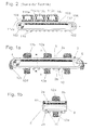
- the conventional arrangement shown in Fig. 2 (see also "Prior Art") consists of an endless, serving as a so-called “worker's belt” conveyor belt 102, which runs over two drums 104, 106, of which a drive drum 104 and the on opposite "end” arranged drum is a tensioning drum 106.
- the leading portion (upper run) of the worker's belt 102 is supported by a slide table 108, the returning portion (Schtrum) of the worker's belt 102 is supported by idlers 110.
- Plate-like parts 112a, ... are mounted on the upper strand, on each of which a scissors table 114a, ... is located.
- the scissor tables are used to adjust the height of moving vehicle bodies, right up to almost finished cars.
- FIG. 1 The embodiment of the invention shown in Fig. 1 has essentially the same basic structure: An endless, serving as a "worker's belt” conveyor belt 2 passes over two drums 4, 6, one of which serves as a drive drum 4 and the other is a tensioning drum 6. The leading section (upper strand 2a) is also here supported by a slide table 8, while the returning portion (Schtrum 2b) of the worker's belt 2 via support rollers 10 runs.
- An endless, serving as a "worker's belt” conveyor belt 2 passes over two drums 4, 6, one of which serves as a drive drum 4 and the other is a tensioning drum 6.
- the leading section (upper strand 2a) is also here supported by a slide table 8, while the returning portion (Schtrum 2b) of the worker's belt 2 via support rollers 10 runs.
- the worker's belt 2 serves as a slide belt. But it is also quite conceivable that between the worker's belt 2 and slide table 8 a so-called wear belt mitACS slide belt is interposed.
- the conveyor belt 2 with new lifting units 12a, ... is provided.
- the slide table 8 is provided for lateral guide boundary of the conveyor belt 2 with side strips 8a, 8b.
- the other details shown here have the same reference numerals as in Fig. 1a, so that it is unnecessary to consider it again.
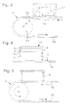
- FIG. 3 shows a belt 2 with a tail pulley (drive 4 or tension drum 6).
- a lifting unit 12 is located on the upper strand 2a of the belt 2 a specially trained lifting cushion (air cushion):
- the base 14 of this lifting cushion 12 has a concave Einsattlung. Height h and width b (or radius r) of the saddle are dimensioned so that the lifting pad 12 can be guided around the drum 4 or 6, without air from the lifting pad 12 would have to be drained.
- the lifting unit 12 shown in Fig. 4 is also a fixedly mounted on the belt 2 air cushion.
- the peculiarity of this air cushion 12 is a multiple horizontal subdivision of the air cushion volume V in horizontal sub-volumes V 1 , ....
- the purpose of such a subdivision into subspaces V 1 , ... is not only to achieve greater stability but also in the adjustability of any lifting height H and thus in a adjustability of any desired working height. If the individual chambers V 1 ,... Have the heights of 1, 2, 4 and 8 units, a total of 15 different heights H can already be set with these four chamber heights H 1 , H 2 , H 3 and H 4 .
- the air bag 12 has a large chamber V 1 for adjusting the main working height H 1 , while the fine adjustment of the height H using smaller, z. B. three, partial volumes V 2 , V 3 , V 4 can be realized.
- FIG. 5 additionally shows a frame 16 located on the belt 2. Its special features consist in that it is likewise fastened on the belt 2 and can be folded in such a way that it can easily rotate around the end drums (drive pulley and tail pulley) 4 and 6 can be performed.
- This frame 16 can either serve as a stabilization frame for an air cushion 12 or else be independent work support without lifting function (without air cushion 12).
Landscapes
- Engineering & Computer Science (AREA)
- Mechanical Engineering (AREA)
- Manufacturing & Machinery (AREA)
- Chemical & Material Sciences (AREA)
- Combustion & Propulsion (AREA)
- Transportation (AREA)
- Structure Of Belt Conveyors (AREA)
- Belt Conveyors (AREA)
- Compositions Of Macromolecular Compounds (AREA)
Description
- Die Erfindung betrifft ein Transportband, insbesondere zur Verwendung als Werkerband in der Automobilindustrie, - gemäß dem Oberbegriff des Anspruchs 1.
- Vormontierte Karosserien von Pkws bis hin zu nahezu fertigen Pkws werden für die Weiter- bzw. Endverarbeitung auf sog. Flurförder-Anlagen bzw. -Elemente gestellt. Bei diesen Transportmitteln handelt es sich üblicherweise um sogenannte Schubplattformen auf "Laufrädern", Metall- oder Kunststoff-Gliederbändern und gleitend abgebogenen Transportbändern aus Gummi oder Kunststoff (sog. Werkerbänder, Spurgleit- und Skidgleitgurte). Der Obertrum der Transportbänder wird entweder von Rollen getragen oder ihre Laufseite weist eine Gleitlage insbesondere auf der Basis textilen Materials auf, mit deren Hilfe sie auf einem ortsfesten Gleittisch entlang gleiten können. "Endseitig" weisen derartige Transportbänder mindestens eine Antriebs- und mindestens eine Spanntrommel auf. Eventuell können Umlenk- und Einschnürrollen vorgesehen sein. Der Betrieb kann ausschließlich vorwärts, aber auch reversierend erfolgen. Die Förderung ist in sämtlichen Richtungen (waagerecht, senkrecht, ansteigend oder abfallend) möglich.
- Um ein bequemes Arbeiten auf den Transportbändern (bzw. -anlagen) zu ermöglichen, sind speziell in der Automobilindustrie als Scherentische ausgebildete sogenannte Hubeinheiten extra auf einzelnen Schubplattformeinheiten angeordnet, die mit den jeweiligen Platten der Mitfahrplattenstraße mitbewegt werden. An jedem Scherentisch sind Betätigungseinrichtungen zur Höheneinstellung für die Kfz-Rohkarosserien oder teilmontierten Pkws vorhanden. Der Rücklauf der Platten geschieht entweder durch Absenken in einen tiefen Keller und Rückführung oder in der gleichen Ebene durch zweimal rechtwinkliges Schwenken der Platten.
Die Mitfahrplatten selbst bestehen aus Holz. Daraus ergeben sich Nachteile wie Verfärbung, Quellen usw.. Es erübrigt sich zu sagen, dass die auf die Mitfahrplatten aufstellbaren Scherentische ziemlich aufwendig gebaut sind. Ihre Bedienung und insbesondere die Rückführung der Mitfahrplatten nebst Scherentische kann nur umständlich durchgeführt werden. - Darüber hinaus gibt es Anwendungen, wo Scherentische direkt auf Werkerbändern stehen. Aber auch in diesem Fall sind die Scherentische nach Durchlaufen der Arbeitsstrecke von den Werkerbändern abzunehmen und in einer anderen Ebene oder seitlich an den Anfang der Laufstrecke zurückzuführen und wieder auf das Band zu stellen.
- Die Aufgabe der Erfindung besteht deshalb darin, eine praktikablere Lösung für eine ergonomische Höhenanpassung des Montagegutes auf einem Werkerband vorzuschlagen und ein separates Rückführen der Höhenverstelleinheit zu vermeiden.
- Die Aufgabe wird im Wesentlichen mit den Merkmalen des Anspruchs 1 gelöst; die Unteransprüche nennen bevorzugte Details und Weiterbildungen.
- Der erfindungsgemäße Vorschlag sieht vor, dass auf dem Band befindliche Hubeinheiten auf dem Band befestigt und zwecks Rückführung in dem Untertrum einfaltbar sind, so dass sie trotz Befestigung auf dem Band "umlauffähig" sind. Aus diesem Grunde brauchen die einzelnen Hubeinheiten nicht separat zurückgeführt zu werden.
- Dies ist insbesondere dann der Fall, wenn die Hubeinheiten aufblasbare Luftkissen sind, die aus Gummi oder elastomerem Material bestehen.
- Zwecks Anhebung von Automobilkarosserien können die Luftkissen am Anfang der Montagestrecke mit Druckluft beaufschlagt werden. Am Ende des Arbeitsweges wird vor dem Rücklauf um die Antriebsrolle die Luft aus den Luftkissen abgelassen, so dass problemlos ein Rücktransport mit dem Untertrum stattfinden kann.
- Wenn das Volumen des jeweiligen Luftkissens in mehrere horizontale Kammern unterteilt ist, lässt sich bequem (fast) jede gewünschte Arbeitshöhe einstellen.
Das Hubkissen kann z. B. in 50 mm Stufen innerhalb von 10 sec auf insgesamt 300 mm Höhe herausgefahren werden.
Zur Erhöhung der Stabilität können die einzelnen Luftkissen mit einem klappbaren (Stahl-)Gestell bzw. Rahmen versehen sein. - In den einzelnen elastomeren Hubkissen kann ein elektrischer Anschluss integriert werden.
- Die Stromversorgung ist durch ein angegossenes Kabel im Gurt oder evtl. induktiv möglich. Eine Bodensteckdose kann mittels kleinem Elastomerblock auf dem Gurt montiert werden.
- Hubkissen (Luftkissen) sind nicht nur einfacher zu handhaben sondern zudem schätzungsweise 50% preiswerter als auf den Schubplattformen angeordnete Scherentische.
Verglichen mit Mitfahrplatten hat das elastische Transportband bezüglich feuchter Medien eine bessere Standfestigkeit. Auch ist für die Werker eine bessere Dämpfung auf der Elastomerunterlage vorhanden.
Ein Hubkissen wird wahlweise alle 8 m angeordnet. Die Werkermitfahrbänder werden bis zu 160 m Achsabstand eingesetzt. An einer Hubkissenstation können ein oder mehrere Hubkissen angeordnet sein. - Ein Ausführungsbeispiel des erfindungsgemäßen Transportbandes und ein Beispiel gemäß dem als nächstkommend angesehenen Standes der Technik ist in den Zeichnungen dargestellt und wird anschließend näher beschrieben, Es zeigt.
- Fig. 1a die Prinzipdarstellung eines erfindungsgemäßen Transportbandes von der Seite betrachtet;
- Fig. 1b dasselbe Transportband als Querschnitt dargestellt (Draufsicht A-A); und
- Fig. 2 die Prinzipdarstellung eines Transportbandes gemäß dem Stand der Technik, ebenfalls von der Seite betrachtet;
- Fig. 3 den Querschnitt durch ein Hubkissen mit speziell ausgebildeter Grundfläche;
- Fig. 4 den Querschnitt durch ein in mehrere horizontale Kammern unterteiltes Hubkissen und
- Fig. 5 ein klappbares Gestell (Rahmen für Hubkissen).
- Die in Fig. 2 dargestellte herkömmliche Anordnung (siehe auch "Stand der Technik") besteht aus einem endlosen, als sogenanntes "Werkerband" dienendes Transportband 102, das über zwei Trommeln 104, 106 läuft, von denen die eine eine Antriebstrommel 104 und die am entgegengesetzten "Ende" angeordnete Trommel eine Spanntrommel 106 ist. Der vorlaufende Abschnitt (Obertrum) des Werkerbandes 102 wird von einem Gleittisch 108, der zurücklaufende Abschnitt (Untertrum) des Werkerbandes 102 wird von Tragrollen 110 unterstützt. Auf dem Obertrum sind plattenähnliche Teile 112a, ... angebracht, auf denen sich jeweils ein Scherentisch 114a, ... befindet. Die Scherentische dienen zur Höheneinstellung darauf mitbewegter Kfz-Rohkarosserien, bis hin zu fast fertigen Pkws.
- Das in Fig. 1 dargestellte Ausführungsbeispiel der Erfindung weist im Wesentlichen denselben Grundaufbau auf: Ein endloses, als "Werkerband" dienendes Transportband 2 läuft über zwei Trommeln 4, 6, von denen die eine als Antriebstrommel 4 dient und die andere eine Spanntrommel 6 ist. Der vorlaufende Abschnitt (Obertrum 2a) wird auch hier von einem Gleittisch 8 unterstützt, während der zurückkehrende Abschnitt (Untertrum 2b) des Werkerbandes 2 über Tragrollen 10 läuft.
- Im vorliegenden Ausführungsbeispiel dient das Werkerband 2 als Gleitgurt. Es ist aber durchaus auch denkbar, dass zwischen Werkerband 2 und Gleittisch 8 ein als sogenannter Verschleißgurt mitlaufender Gleitgurt zwischengeschaltet wird.
- Erfindungswesentlich ist, dass das Transportband 2 mit neuartigen Hubeinheiten 12a, ... versehen ist. Im dargestellten Ausführungsbeispiel sind die Hubeinheiten 12a, ... aufblasbare Luftkissen, die mit dem Transportband 2 fest verbunden sind. Aus dieser Abbildung geht weiter hervor, dass die momentan oberhalb des Obertrums 2a des Transportbandes 2 befindlichen Luftkissen 12a, 12b aufgeblasen sind, während sie, wenn sie sich im Bereich der Antriebs- 4, der Spanntrommel 6 und unterhalb des Untertrums 2b des Transportbandes 2 befinden, abgelassen sind und schlapp herunterhängen.
- Um die Luftkissen 12a, ... "umlauffähig" zu machen, braucht nur relativ wenig Luft aus den sonst prall gefüllten Luftkissen 12a, ... abgelassen zu werden.
Das Auffüllen bzw. das Nachfüllen mit Druckluft am Anfang der Werkerstrecke kann über einen extern bereitgehaltenen Druckschlauch im Bereich der Bestückung erfolgen.
Es ist aber auch denkbar, dass die einzelnen Luftkissen 12a, ... jeweils einen kleinen mitgeführten Kompressor aufweisen, die z. B. über Schleifkontakte oder Induktionsschleifen mit Strom versorgt werden. - Wie aus Fig. 1b hervorgeht, ist der Gleittisch 8 zur seitlichen Führungsbegrenzung des Transportbandes 2 mit Seitenleisten 8a, 8b versehen. Die weiteren, hier dargestellten Details weisen dieselben Bezugszeichen wie in Fig. 1a auf, so dass es sich erübrigt, erneut hierauf einzugehen.
- Der in Fig. 3 dargestellte Ausschnitt zeigt ein Band 2 mit einer Umlenktrommel (Antriebs-4 oder Spanntrommel 6). Als Hubeinheit 12 befindet sich auf dem Obertrum 2a des Bandes 2 ein speziell ausgebildetes Hubkissen (Luftkissen): Die Grundfläche 14 dieses Hubkissens 12 weist eine konkave Einsattlung auf. Höhe h und Breite b (bzw. Radius r) der Einsattelung sind so dimensioniert, dass das Hubkissen 12 um die Trommel 4 bzw. 6 geführt werden kann, ohne dass Luft aus dem Hubkissen 12 abgelassen werden müsste. Auch falls die Größe h, b der an der Grundfläche 14 des Hubkissens 12 befindliche Einsattelung nicht völlig ausreichen sollte, die endseitige Umlenktrommel 4 bzw. 6 ohne Deformation zu umrunden, so würde bereits ein nur teilweises Luftablassen genügen, um eine hinreichende Anpassung an den Krümmungsradius R der Trommeln 4 und 6 zu erreichen.
- Die in der Fig. 4 dargestellte Hubeinheit 12 ist ebenfalls ein fest auf dem Band 2 angebrachtes Luftkissen. Die Besonderheit dieses Luftkissens 12 besteht in einer mehrfachen horizontalen Unterteilung des Luftkissen-Volumens V in horizontale Teilvolumina V1, .... Der Zweck einer solchen Unterteilung in Teilräume V1, ... besteht nicht nur in der Erzielung einer größeren Stabilität sondern auch in der Einstellbarkeit einer beliebigen Hubhöhe H und damit in einer Einstellbarkeit jeder gewünschten Arbeitshöhe. Weisen die einzelnen Kammern V1, ... die Höhen von 1, 2, 4 und 8 Einheiten auf, so lassen sich bereits mit diesen vier Kammerhöhen H1, H2, H3 und H4 insgesamt 15 verschiedene Höhen H einstellen. (Von 1 bis 15 in Einser-Schritten.)
Alternativ weist das Luftkissen 12 eine große Kammer V1 zur Einstellung der Hauptarbeitshöhe H1 auf, während die Feinanpassung der Höhe H mit Hilfe kleiner, z. B. dreier, Teilvolumina V2, V3, V4 realisiert werden kann. - Die Fig. 5 zeigt ergänzend ein auf dem Band 2 befindliches Gestell 16. Seine besonderen Merkmale bestehen darin, dass es ebenfalls auf dem Band 2 befestigt und in der Weise klappbar ist, dass es problemlos um die endseitigen Trommeln (Antriebs- und Umlenktrommel) 4 und 6 geführt werden kann.
Dieses Gestell 16 kann entweder als Stabilisierungsrahmen für ein Luftkissen 12 dienen oder aber auch eigenständige Arbeitsunterlage ohne Hubfunktion (ohne Luftkissen 12) sein. -
- a) Stand der Technik
- 102
- Transportband ("Werkerband")
- 104, 106
- Trommeln
- 104
- Antriebstrommel
- 106
- Spanntrommel
- 108
- Gleittisch
- 110
- Tragrolle(n)
- 112a, ...
- plattenähnliche Teile, Platte(n) (einer Mitfahrplattenstraße)
- 114a, ...
- Scherentisch(e)
- b) Erfindung
- 2
- Transportband ("Werkerband"), Band
- 2a
- Obertrum (des Transportbandes)
- 2b
- Untertrum (des Transportbandes)
- 4
- Antriebstrommel, -rolle
- 6
- Spanntrommel, -rolle
- 8
- Gleittisch
- 8a, 8b
- Seitenleiste(n) des Gleittisches
- 10
- Tragrolle(n)
- 12; 12a, ...
- Hubeinheit(en), Hubkissen, Luftkissen
- 14
- Grundfläche eines Hubkissens
- V
- Volumen eines Hubkissens
- V1,...
- Kammern eines Hubkissens (Mehrkammerhubkissen), Teilvolumen eines Hubkissens, Teilräume, Kammer(n)
- h, b, r
- Höhe, Breite, Radius einer Einsattelung
- H; H1, ...
- Hubhöhe eines Luftkissens, Arbeitshöhe
- 16
- "umlauffähiges" Gestell, "umlauffähiger" Rahmen
- R
- Krümmungsradius der Trommeln
Claims (9)
- Transportbandanlage mit einem endlosen elastischen Transportband (2) aus Gummi oder Kunststoff, das umlaufend gleitend und/oder mittels Tragrollen (10) rollend abgetragen ist,- mit mindestens einer Antriebs- (4) und mindestens einer Spanntrommel (6);- sowie evtl. mit Umlenk- und Einschnürrollen;- vorwärts oder reversierend betreibbar;- waagerecht, ansteigend oder abfallend fördernd,wobei die Tragseite des Transportbandes (2) mit mindestens einer Hubeinheit (12a, ...) versehen ist,
dadurch gekennzeichnet,
dass die mindestens eine Hubeinheit (12a...) auf dem Transportband befestigt ist und mit diesem umläuft,
dass die mindestens eine Hubeinheit (12a...) zwecks Rückführung entlang dem Untertrum (2b) des Transportbandes (2) einfaltbar ist. - Transportbandanlage nach Anspruch 1,
dadurch gekennzeichnet,
dass die mindestens eine Hubeinheit (12a, ...) ein aus Gummi oder elastomerem Material bestehendes Luftkissen ist. - Transportbandanlage nach Anspruch 2,
dadurch gekennzeichnet,
dass während des Betriebs des Transportbandes (2) Druckluft in das mindestens eine Luftkissen (12a,...) auffüllbar oder ablassbar ist. - Transportbandanlage nach einem der Ansprüche 2 bis 3,
dadurch gekennzeichnet,
dass das mindestens eine auf dem Transportband (2) befindliche Luftkissen (12a...) während des Zustands als Obertrum (2a) aufgeblasen ist, während es im Bereich der Antriebs- (4) und/oder der Spanntrommel (6) und im Zustand als Untertrum (2b) abgelassen oder flach angesaugt ist. - Transportbandanlage nach einem der Ansprüche 2 bis 4,
dadurch gekennzeichnet,
dass die Grundfläche (14) des mindestens einen Luftkissens (12a, ...) eine konkave Einsattelung aufweist,
wobei Höhe (h) und Breite (b) und/oder Radius (r) der Einsattelung so dimensioniert sind, dass das mindestens eine Luftkissen (12a, ...) um die Trommeln (4 und 6) geführt werden kann, ohne dass Luft aus dem mindestens einen Luftkissen (12a,...) abgelassen werden müsste. - Transportbandanlage nach einem der Ansprüche 2 bis 5,
dadurch gekennzeichnet,
dass das Volumen (V) des mindestens einen Luftkissens (12a, ...) in mehrere horizontale Kammern (V1...), die einzeln mit Druckluft beaufschlagbar sind, unterteilt ist. - Transportbandanlage nach einem der Ansprüche 1 bis 6,
dadurch gekennzeichnet,
dass die mindestens eine Hubeinheit (12a,...) einen in seiner Höhe einfaltbaren Rahmen (16) aufweist. - Transportbandanlage nach einem der Ansprüche 6 bis 7,
dadurch gekennzeichnet,
dass eine feste Hubposition programmierbar oder eine individuelle Hubveränderung an jedem Arbeitsschritt einstellbar ist. - Transportbandanlage nach einem der Ansprüche 1 bis 8,
dadurch gekennzeichnet,
dass das Transportband (2) Teil einer Spurgleit- oder Werkerbandanlage ist.
Priority Applications (1)
| Application Number | Priority Date | Filing Date | Title |
|---|---|---|---|
| PL04105953T PL1557378T3 (pl) | 2004-01-20 | 2004-11-22 | Przenośnik taśmowy, zwłaszcza do stosowania jako taśma montażowa |
Applications Claiming Priority (2)
| Application Number | Priority Date | Filing Date | Title |
|---|---|---|---|
| DE102004002738 | 2004-01-20 | ||
| DE102004002738A DE102004002738A1 (de) | 2004-01-20 | 2004-01-20 | Transportband, insbesondere zur Verwendung als Werkerband |
Publications (2)
| Publication Number | Publication Date |
|---|---|
| EP1557378A1 EP1557378A1 (de) | 2005-07-27 |
| EP1557378B1 true EP1557378B1 (de) | 2007-05-30 |
Family
ID=34625717
Family Applications (1)
| Application Number | Title | Priority Date | Filing Date |
|---|---|---|---|
| EP04105953A Expired - Lifetime EP1557378B1 (de) | 2004-01-20 | 2004-11-22 | Transportband, insbesondere zur Verwendung als Werkerband |
Country Status (6)
| Country | Link |
|---|---|
| EP (1) | EP1557378B1 (de) |
| AT (1) | ATE363445T1 (de) |
| DE (2) | DE102004002738A1 (de) |
| ES (1) | ES2287645T3 (de) |
| PL (1) | PL1557378T3 (de) |
| PT (1) | PT1557378E (de) |
Families Citing this family (6)
| Publication number | Priority date | Publication date | Assignee | Title |
|---|---|---|---|---|
| DE102007041790A1 (de) | 2007-09-03 | 2009-03-05 | AFT Förderanlagen Bautzen GmbH & Co. KG | Bandförderer |
| DE102010045013A1 (de) * | 2010-09-10 | 2012-03-15 | Eisenmann Ag | Vorrichtung zum Fördern von Fahrzeugkarosserien |
| DE102011102694B4 (de) * | 2011-05-28 | 2020-06-18 | Eisenmann Se | Modulband und Modulbandförderer |
| DE102013007852B4 (de) * | 2013-05-08 | 2016-06-02 | Sew-Eurodrive Gmbh & Co Kg | Anlage mit Gliederkette |
| JP6311034B2 (ja) | 2014-01-16 | 2018-04-11 | フォルボ・ジークリング・ゲゼルシャフト・ミト・ベシュレンクテル・ハフツング | 搬送ベルト及びこの搬送ベルト装備した搬送装置 |
| CN111056208A (zh) * | 2020-01-09 | 2020-04-24 | 南宁师范大学 | 一种机械式物流仓库用物流移动设备 |
Family Cites Families (2)
| Publication number | Priority date | Publication date | Assignee | Title |
|---|---|---|---|---|
| IT1250290B (it) * | 1991-08-13 | 1995-04-07 | Fiat Auto Spa | Sistema trasportatore, particolarmente per autoveicoli, con dispositivo di sollevamento. |
| DE19858989A1 (de) * | 1998-12-21 | 2000-06-29 | Volkswagen Ag | Montage- und/oder Transportband für die Montage oder den Transport eines Kraftfahrzeugs |
-
2004
- 2004-01-20 DE DE102004002738A patent/DE102004002738A1/de not_active Withdrawn
- 2004-11-22 DE DE502004003937T patent/DE502004003937D1/de not_active Expired - Lifetime
- 2004-11-22 PT PT04105953T patent/PT1557378E/pt unknown
- 2004-11-22 EP EP04105953A patent/EP1557378B1/de not_active Expired - Lifetime
- 2004-11-22 AT AT04105953T patent/ATE363445T1/de not_active IP Right Cessation
- 2004-11-22 PL PL04105953T patent/PL1557378T3/pl unknown
- 2004-11-22 ES ES04105953T patent/ES2287645T3/es not_active Expired - Lifetime
Also Published As
| Publication number | Publication date |
|---|---|
| DE102004002738A1 (de) | 2005-08-11 |
| PL1557378T3 (pl) | 2007-10-31 |
| ES2287645T3 (es) | 2007-12-16 |
| ATE363445T1 (de) | 2007-06-15 |
| EP1557378A1 (de) | 2005-07-27 |
| PT1557378E (pt) | 2007-08-20 |
| DE502004003937D1 (de) | 2007-07-12 |
Similar Documents
| Publication | Publication Date | Title |
|---|---|---|
| EP3057845B1 (de) | Fördereinheit und fördersystem zum fördern von ladungsträgern | |
| DE2416642C3 (de) | Vorrichtung zum Transport eines Lastkörpers in Tagebaubetrieben, insbesondere zum Rücken von Bandantriebsstationen | |
| DE69915560T2 (de) | Vorrichtung zum Ueberfuehren von Waren | |
| EP2578520B1 (de) | Fördervorrichtung | |
| DE2648340A1 (de) | Foerdergeraet | |
| DE9418354U1 (de) | Lastklemmvorrichtung mit erweitertem vertikalem Bewegungsbereich | |
| DE69309943T2 (de) | Aufblasbares förderband | |
| DE3004371A1 (de) | Frachttransporter zum transportieren von ladungen | |
| DE10318621A1 (de) | Förderer zum Transportieren von Lastträgern | |
| EP1557378B1 (de) | Transportband, insbesondere zur Verwendung als Werkerband | |
| DE69016336T2 (de) | Faltbares Verdeck für eine Ladefläche. | |
| AT518568B1 (de) | Regalbediengerät | |
| DE1854786U (de) | Fahrbares foerder- und hubgeraet. | |
| DE3930626A1 (de) | Nutzfahrzeug mit beweglichem ladeboden | |
| AT398302B (de) | Vorrichtung zum lagern von tafel- oder plattenförmigen gegenständen | |
| DE3532465A1 (de) | Vorrichtung zum transportieren von stueckgut | |
| DE10315404B4 (de) | Fördersystem für Behälter, insbesondere eine Flughafen-Gepäckförderanlage | |
| DE8015355U1 (de) | Rollenboden, insbesondere für Fahrzeuge | |
| DE1060321B (de) | Hubkarren | |
| DE10018325A1 (de) | Ladevorrichtung für ein Transportfahrzeug | |
| DE4219830A1 (de) | Statische Trimmung für ein Luftkissenfahrzeug | |
| KR20250107605A (ko) | 횡단통로를 만들 수 있는 컨베이어 라인 | |
| DE1129108B (de) | Seitenlader mit querverschiebbarem Hubmast | |
| DE3806036A1 (de) | Transportsystem | |
| DE4217789C2 (de) | Aufgabestation für einen Bandförderer |
Legal Events
| Date | Code | Title | Description |
|---|---|---|---|
| PUAI | Public reference made under article 153(3) epc to a published international application that has entered the european phase |
Free format text: ORIGINAL CODE: 0009012 |
|
| AK | Designated contracting states |
Kind code of ref document: A1 Designated state(s): AT BE BG CH CY CZ DE DK EE ES FI FR GB GR HU IE IS IT LI LU MC NL PL PT RO SE SI SK TR |
|
| AX | Request for extension of the european patent |
Extension state: AL HR LT LV MK YU |
|
| 17P | Request for examination filed |
Effective date: 20060127 |
|
| AKX | Designation fees paid |
Designated state(s): AT BE BG CH CY CZ DE DK EE ES FI FR GB GR HU IE IS IT LI LU MC NL PL PT RO SE SI SK TR |
|
| GRAP | Despatch of communication of intention to grant a patent |
Free format text: ORIGINAL CODE: EPIDOSNIGR1 |
|
| GRAS | Grant fee paid |
Free format text: ORIGINAL CODE: EPIDOSNIGR3 |
|
| GRAA | (expected) grant |
Free format text: ORIGINAL CODE: 0009210 |
|
| AK | Designated contracting states |
Kind code of ref document: B1 Designated state(s): AT BE BG CH CY CZ DE DK EE ES FI FR GB GR HU IE IS IT LI LU MC NL PL PT RO SE SI SK TR |
|
| PG25 | Lapsed in a contracting state [announced via postgrant information from national office to epo] |
Ref country code: FI Free format text: LAPSE BECAUSE OF FAILURE TO SUBMIT A TRANSLATION OF THE DESCRIPTION OR TO PAY THE FEE WITHIN THE PRESCRIBED TIME-LIMIT Effective date: 20070530 |
|
| REG | Reference to a national code |
Ref country code: GB Ref legal event code: FG4D Free format text: NOT ENGLISH |
|
| REG | Reference to a national code |
Ref country code: CH Ref legal event code: EP |
|
| REG | Reference to a national code |
Ref country code: IE Ref legal event code: FG4D Free format text: LANGUAGE OF EP DOCUMENT: GERMAN |
|
| REF | Corresponds to: |
Ref document number: 502004003937 Country of ref document: DE Date of ref document: 20070712 Kind code of ref document: P |
|
| REG | Reference to a national code |
Ref country code: RO Ref legal event code: EPE |
|
| REG | Reference to a national code |
Ref country code: PT Ref legal event code: SC4A Free format text: AVAILABILITY OF NATIONAL TRANSLATION Effective date: 20070806 |
|
| REG | Reference to a national code |
Ref country code: SE Ref legal event code: TRGR |
|
| PG25 | Lapsed in a contracting state [announced via postgrant information from national office to epo] |
Ref country code: IS Free format text: LAPSE BECAUSE OF NON-PAYMENT OF DUE FEES Effective date: 20070930 |
|
| REG | Reference to a national code |
Ref country code: PL Ref legal event code: T3 |
|
| ET | Fr: translation filed | ||
| NLV1 | Nl: lapsed or annulled due to failure to fulfill the requirements of art. 29p and 29m of the patents act | ||
| REG | Reference to a national code |
Ref country code: ES Ref legal event code: FG2A Ref document number: 2287645 Country of ref document: ES Kind code of ref document: T3 |
|
| GBV | Gb: ep patent (uk) treated as always having been void in accordance with gb section 77(7)/1977 [no translation filed] |
Effective date: 20070530 |
|
| REG | Reference to a national code |
Ref country code: IE Ref legal event code: FD4D |
|
| PG25 | Lapsed in a contracting state [announced via postgrant information from national office to epo] |
Ref country code: NL Free format text: LAPSE BECAUSE OF FAILURE TO SUBMIT A TRANSLATION OF THE DESCRIPTION OR TO PAY THE FEE WITHIN THE PRESCRIBED TIME-LIMIT Effective date: 20070530 Ref country code: IE Free format text: LAPSE BECAUSE OF FAILURE TO SUBMIT A TRANSLATION OF THE DESCRIPTION OR TO PAY THE FEE WITHIN THE PRESCRIBED TIME-LIMIT Effective date: 20070530 Ref country code: DK Free format text: LAPSE BECAUSE OF FAILURE TO SUBMIT A TRANSLATION OF THE DESCRIPTION OR TO PAY THE FEE WITHIN THE PRESCRIBED TIME-LIMIT Effective date: 20070530 Ref country code: SI Free format text: LAPSE BECAUSE OF FAILURE TO SUBMIT A TRANSLATION OF THE DESCRIPTION OR TO PAY THE FEE WITHIN THE PRESCRIBED TIME-LIMIT Effective date: 20070530 Ref country code: BG Free format text: LAPSE BECAUSE OF FAILURE TO SUBMIT A TRANSLATION OF THE DESCRIPTION OR TO PAY THE FEE WITHIN THE PRESCRIBED TIME-LIMIT Effective date: 20070830 |
|
| PLBE | No opposition filed within time limit |
Free format text: ORIGINAL CODE: 0009261 |
|
| STAA | Information on the status of an ep patent application or granted ep patent |
Free format text: STATUS: NO OPPOSITION FILED WITHIN TIME LIMIT |
|
| PG25 | Lapsed in a contracting state [announced via postgrant information from national office to epo] |
Ref country code: GR Free format text: LAPSE BECAUSE OF FAILURE TO SUBMIT A TRANSLATION OF THE DESCRIPTION OR TO PAY THE FEE WITHIN THE PRESCRIBED TIME-LIMIT Effective date: 20070831 Ref country code: GB Free format text: LAPSE BECAUSE OF FAILURE TO SUBMIT A TRANSLATION OF THE DESCRIPTION OR TO PAY THE FEE WITHIN THE PRESCRIBED TIME-LIMIT Effective date: 20070530 Ref country code: IT Free format text: LAPSE BECAUSE OF FAILURE TO SUBMIT A TRANSLATION OF THE DESCRIPTION OR TO PAY THE FEE WITHIN THE PRESCRIBED TIME-LIMIT Effective date: 20070530 |
|
| 26N | No opposition filed |
Effective date: 20080303 |
|
| PG25 | Lapsed in a contracting state [announced via postgrant information from national office to epo] |
Ref country code: MC Free format text: LAPSE BECAUSE OF NON-PAYMENT OF DUE FEES Effective date: 20071130 |
|
| PG25 | Lapsed in a contracting state [announced via postgrant information from national office to epo] |
Ref country code: EE Free format text: LAPSE BECAUSE OF FAILURE TO SUBMIT A TRANSLATION OF THE DESCRIPTION OR TO PAY THE FEE WITHIN THE PRESCRIBED TIME-LIMIT Effective date: 20070530 |
|
| PG25 | Lapsed in a contracting state [announced via postgrant information from national office to epo] |
Ref country code: AT Free format text: LAPSE BECAUSE OF NON-PAYMENT OF DUE FEES Effective date: 20071122 |
|
| REG | Reference to a national code |
Ref country code: CH Ref legal event code: PL |
|
| PG25 | Lapsed in a contracting state [announced via postgrant information from national office to epo] |
Ref country code: CY Free format text: LAPSE BECAUSE OF FAILURE TO SUBMIT A TRANSLATION OF THE DESCRIPTION OR TO PAY THE FEE WITHIN THE PRESCRIBED TIME-LIMIT Effective date: 20070530 |
|
| PG25 | Lapsed in a contracting state [announced via postgrant information from national office to epo] |
Ref country code: LU Free format text: LAPSE BECAUSE OF NON-PAYMENT OF DUE FEES Effective date: 20071122 |
|
| PG25 | Lapsed in a contracting state [announced via postgrant information from national office to epo] |
Ref country code: TR Free format text: LAPSE BECAUSE OF FAILURE TO SUBMIT A TRANSLATION OF THE DESCRIPTION OR TO PAY THE FEE WITHIN THE PRESCRIBED TIME-LIMIT Effective date: 20070530 Ref country code: HU Free format text: LAPSE BECAUSE OF FAILURE TO SUBMIT A TRANSLATION OF THE DESCRIPTION OR TO PAY THE FEE WITHIN THE PRESCRIBED TIME-LIMIT Effective date: 20071201 |
|
| PG25 | Lapsed in a contracting state [announced via postgrant information from national office to epo] |
Ref country code: CH Free format text: LAPSE BECAUSE OF NON-PAYMENT OF DUE FEES Effective date: 20081130 Ref country code: LI Free format text: LAPSE BECAUSE OF NON-PAYMENT OF DUE FEES Effective date: 20081130 |
|
| PGFP | Annual fee paid to national office [announced via postgrant information from national office to epo] |
Ref country code: CZ Payment date: 20091120 Year of fee payment: 6 Ref country code: DE Payment date: 20091119 Year of fee payment: 6 Ref country code: ES Payment date: 20091123 Year of fee payment: 6 Ref country code: SE Payment date: 20091112 Year of fee payment: 6 |
|
| PGFP | Annual fee paid to national office [announced via postgrant information from national office to epo] |
Ref country code: SK Payment date: 20091119 Year of fee payment: 6 Ref country code: PL Payment date: 20091028 Year of fee payment: 6 |
|
| PGFP | Annual fee paid to national office [announced via postgrant information from national office to epo] |
Ref country code: PT Payment date: 20091109 Year of fee payment: 6 |
|
| PGFP | Annual fee paid to national office [announced via postgrant information from national office to epo] |
Ref country code: FR Payment date: 20091201 Year of fee payment: 6 Ref country code: RO Payment date: 20091103 Year of fee payment: 6 |
|
| PGFP | Annual fee paid to national office [announced via postgrant information from national office to epo] |
Ref country code: BE Payment date: 20091224 Year of fee payment: 6 |
|
| REG | Reference to a national code |
Ref country code: PT Ref legal event code: MM4A Free format text: LAPSE DUE TO NON-PAYMENT OF FEES Effective date: 20110523 |
|
| BERE | Be: lapsed |
Owner name: CONTITECH TRANSPORTBANDSYSTEME G.M.B.H. Effective date: 20101130 |
|
| REG | Reference to a national code |
Ref country code: SE Ref legal event code: EUG |
|
| PG25 | Lapsed in a contracting state [announced via postgrant information from national office to epo] |
Ref country code: PT Free format text: LAPSE BECAUSE OF NON-PAYMENT OF DUE FEES Effective date: 20110523 Ref country code: CZ Free format text: LAPSE BECAUSE OF NON-PAYMENT OF DUE FEES Effective date: 20101122 |
|
| REG | Reference to a national code |
Ref country code: SK Ref legal event code: MM4A Ref document number: E 2233 Country of ref document: SK Effective date: 20101122 |
|
| REG | Reference to a national code |
Ref country code: FR Ref legal event code: ST Effective date: 20110801 |
|
| PG25 | Lapsed in a contracting state [announced via postgrant information from national office to epo] |
Ref country code: BE Free format text: LAPSE BECAUSE OF NON-PAYMENT OF DUE FEES Effective date: 20101130 Ref country code: SK Free format text: LAPSE BECAUSE OF NON-PAYMENT OF DUE FEES Effective date: 20101122 |
|
| PG25 | Lapsed in a contracting state [announced via postgrant information from national office to epo] |
Ref country code: SE Free format text: LAPSE BECAUSE OF NON-PAYMENT OF DUE FEES Effective date: 20101123 |
|
| REG | Reference to a national code |
Ref country code: DE Ref legal event code: R119 Ref document number: 502004003937 Country of ref document: DE Effective date: 20110601 Ref country code: DE Ref legal event code: R119 Ref document number: 502004003937 Country of ref document: DE Effective date: 20110531 |
|
| PG25 | Lapsed in a contracting state [announced via postgrant information from national office to epo] |
Ref country code: FR Free format text: LAPSE BECAUSE OF NON-PAYMENT OF DUE FEES Effective date: 20101130 |
|
| PG25 | Lapsed in a contracting state [announced via postgrant information from national office to epo] |
Ref country code: RO Free format text: LAPSE BECAUSE OF NON-PAYMENT OF DUE FEES Effective date: 20101122 |
|
| REG | Reference to a national code |
Ref country code: ES Ref legal event code: FD2A Effective date: 20120110 |
|
| PG25 | Lapsed in a contracting state [announced via postgrant information from national office to epo] |
Ref country code: ES Free format text: LAPSE BECAUSE OF NON-PAYMENT OF DUE FEES Effective date: 20101123 |
|
| REG | Reference to a national code |
Ref country code: PL Ref legal event code: LAPE |
|
| PG25 | Lapsed in a contracting state [announced via postgrant information from national office to epo] |
Ref country code: PL Free format text: LAPSE BECAUSE OF NON-PAYMENT OF DUE FEES Effective date: 20101122 |
|
| PG25 | Lapsed in a contracting state [announced via postgrant information from national office to epo] |
Ref country code: DE Free format text: LAPSE BECAUSE OF NON-PAYMENT OF DUE FEES Effective date: 20110531 |