EP1554496B1 - Machine de compression pourvue de deux rotors a rotation en sens inverse - Google Patents
Machine de compression pourvue de deux rotors a rotation en sens inverse Download PDFInfo
- Publication number
- EP1554496B1 EP1554496B1 EP03809330A EP03809330A EP1554496B1 EP 1554496 B1 EP1554496 B1 EP 1554496B1 EP 03809330 A EP03809330 A EP 03809330A EP 03809330 A EP03809330 A EP 03809330A EP 1554496 B1 EP1554496 B1 EP 1554496B1
- Authority
- EP
- European Patent Office
- Prior art keywords
- housing
- compressor machine
- wall
- rotors
- machine according
- Prior art date
- Legal status (The legal status is an assumption and is not a legal conclusion. Google has not performed a legal analysis and makes no representation as to the accuracy of the status listed.)
- Expired - Lifetime
Links
Images
Classifications
-
- F—MECHANICAL ENGINEERING; LIGHTING; HEATING; WEAPONS; BLASTING
- F04—POSITIVE - DISPLACEMENT MACHINES FOR LIQUIDS; PUMPS FOR LIQUIDS OR ELASTIC FLUIDS
- F04C—ROTARY-PISTON, OR OSCILLATING-PISTON, POSITIVE-DISPLACEMENT MACHINES FOR LIQUIDS; ROTARY-PISTON, OR OSCILLATING-PISTON, POSITIVE-DISPLACEMENT PUMPS
- F04C29/00—Component parts, details or accessories of pumps or pumping installations, not provided for in groups F04C18/00 - F04C28/00
- F04C29/0042—Driving elements, brakes, couplings, transmissions specially adapted for pumps
- F04C29/005—Means for transmitting movement from the prime mover to driven parts of the pump, e.g. clutches, couplings, transmissions
-
- F—MECHANICAL ENGINEERING; LIGHTING; HEATING; WEAPONS; BLASTING
- F04—POSITIVE - DISPLACEMENT MACHINES FOR LIQUIDS; PUMPS FOR LIQUIDS OR ELASTIC FLUIDS
- F04C—ROTARY-PISTON, OR OSCILLATING-PISTON, POSITIVE-DISPLACEMENT MACHINES FOR LIQUIDS; ROTARY-PISTON, OR OSCILLATING-PISTON, POSITIVE-DISPLACEMENT PUMPS
- F04C18/00—Rotary-piston pumps specially adapted for elastic fluids
- F04C18/08—Rotary-piston pumps specially adapted for elastic fluids of intermeshing-engagement type, i.e. with engagement of co-operating members similar to that of toothed gearing
- F04C18/12—Rotary-piston pumps specially adapted for elastic fluids of intermeshing-engagement type, i.e. with engagement of co-operating members similar to that of toothed gearing of other than internal-axis type
-
- F—MECHANICAL ENGINEERING; LIGHTING; HEATING; WEAPONS; BLASTING
- F04—POSITIVE - DISPLACEMENT MACHINES FOR LIQUIDS; PUMPS FOR LIQUIDS OR ELASTIC FLUIDS
- F04C—ROTARY-PISTON, OR OSCILLATING-PISTON, POSITIVE-DISPLACEMENT MACHINES FOR LIQUIDS; ROTARY-PISTON, OR OSCILLATING-PISTON, POSITIVE-DISPLACEMENT PUMPS
- F04C29/00—Component parts, details or accessories of pumps or pumping installations, not provided for in groups F04C18/00 - F04C28/00
- F04C29/04—Heating; Cooling; Heat insulation
Definitions
- the invention relates to a compressor machine with two counter-rotating rotors, which are mounted on two parallel, spaced-apart and mounted in a housing shafts, one of which is driven directly and the other by intermeshing, mounted on the shafts gears.
- Compressor machines with two oppositely rotating rotors can work as compressors or vacuum pumps.
- EP 1 163 450 A1 such a machine with claw-type rotor blades is known, which can generate both suction air and blown air and is particularly suitable for use in the field of paper processing. Due to the internal compression of such machines, significantly higher pressure ratios can be achieved than e.g. by means of a roots pump.
- By flying arrangement of the rotors in a pot-like housing a simple construction is achieved.
- the two waves coupling gear on the one hand and the shaft bearing on the other hand are arranged in separate housing parts, which must be exactly aligned and pinned.
- the cup-shaped housing receiving the rotors must be pinned exactly to the transmission housing. This results in the need to edit pin holes as accurately as possible from two different sides of a housing part. Inaccuracies lead to skewed shafts and thus increased bearing loads, gear noise and other malfunctions.
- US 2,635,552 A discloses a rotary pump for pumping liquids primarily from the food sector.
- the pump has two parallel shafts to each of which a rotor is mounted flying. It comprises a gear housing with a gear chamber for receiving gear wheels and a housing bolted to the gear housing with a working chamber for receiving the rotors. The bearing of the waves takes place in the end walls of the gear chamber.
- US 1,386,792 A discloses a rotary blower with a housing and two parallel shafts to each of which a rotor is mounted.
- a working chamber In the housing, a working chamber, a gear chamber and an air chamber therebetween are arranged.
- the working chamber is bounded on one side by a radial cover. The storage of the waves takes place in a transmission chamber limiting frontal outer wall and in the radial cover.
- the invention provides a compacting machine in which, despite simplified manufacture and a reduced number of parts, precise alignment of the shafts is ensured.
- the compressor machine according to the invention has two rotors running in opposite directions, which are mounted on two parallel, spaced-apart and mounted in a housing shafts. One of the waves is direct and the other by intermeshing waves Gears driven.
- the housing has two integral with each other and with a peripheral wall formed radial walls in which the shafts are mounted. Between these radial walls, the gears are arranged. A side wall of the housing has a closed by a removable lid opening. With the cover removed, the gears can be mounted on the shafts through this opening.
- the bearing bores for the shafts can be mounted and machined in the one-piece housing with a single set-up so that with minimal number of parts any cause of alignment errors is eliminated.
- the lid closing the opening in the side wall of the housing has no influence on the bearing of the shafts. It is a simple part that only has to close the opening and seal against oil leakage. It has been found that the so avoided even small misalignments leads to better efficiency and reduced running noise.
- one of the radial walls is a radial outer wall and the other an intermediate wall which delimits on its one side with the radial outer wall a gear housing receiving the gears and on its other side a rotor accommodating the working chamber.
- the compressor machine according to the invention is characterized in that the working chamber is closed on the side facing away from the intermediate wall end face by a radial housing cover; the housing forms a monobloc base body, which has an opening at its front end facing the housing cover, the width of which is the largest of all located in the interior of the housing axial passages and holes, so that they are accessible for processing through this opening in a clamping of the body are, and that the intermediate wall in turn has axially through openings for receiving Wellenlagem whose width is greater than that of the axial bearing bores in the radial outer wall.
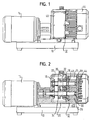
- the compressor machine described here by way of example has rotors with claw-shaped rotor blades and can be operated both as a compressor and as a vacuum pump.
- an integrally molded housing body 12 is mounted with a flanged electric motor 14.
- the housing body 12 has two radial, parallel and spaced apart walls 16, 18 which are interconnected by a peripheral wall 20.
- the radial wall 16 forms an outer wall.
- the radial wall 18 forms an intermediate wall of the housing body 12 and defines a transmission chamber 22 formed between the walls 16, 18 from a working chamber 24 which receives two rotors 26, 28 with claw-like rotor blades.
- the rotor 26 is mounted in a floating manner on an axial end of a shaft 30, which is mounted in the radial walls 16, 18. The opposite axial end of the shaft 30 is coupled directly to the output shaft of the electric motor 14.
- the rotor 28 is mounted in a floating manner on an axial end of a second shaft 32, which is likewise mounted in the radial walls 16, 18.
- the shafts 30, 32 are parallel and spaced apart.
- the shafts 30, 32 are coupled together by two intermeshing, arranged in the gear chamber 22 gears 34, 36, so that they rotate synchronously and in opposite directions of rotation.
- the housing body 12 has a side wall with an opening 38 which can be closed by a lid 40 fitted from outside. This opening 38 is dimensioned so that when removed cover 40, the gears 34, 36 in the gear chamber 22 for mounting on the shafts 30, 32 can be introduced.
- a bearing cover plate 42 is attached to the intermediate wall 18. At its end remote from the bearing cover plate 42 axial end of the working chamber 24 is closed by a radial housing cover 44.
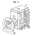
- a hood 46 To the housing cover 44 includes a hood 46, which encloses a coupled for example with the shaft 30 or having a third-party drive fan.
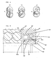
- the described compressor machine is preferably a so-called "claw compressor", ie a machine with claw-shaped rotor blades and with internal compression.
- Figure 4 shows three phases in the cycle of such a machine, namely at a) the beginning of the compression process, at b) the advanced compression process and at c) the phase of pushing out the compacted volume.
- the phase shown in Figure 4a) is preceded by the inlet phase, in which a common inlet chamber is filled, then divided into two Operakammem and finally merged into a common volume, which then undergoes the internal compression.
- An outlet port denoted by A is closed during rotation of the rotors during the phase of internal compression and during the inlet phase by one of the end faces of the lower rotor.
- the outlet opening A is released by the lower rotor, so that the compressed volume can be ejected through the outlet port A.
- This outlet opening leads axially through the housing cover 44 out of the working space of the compressor machine.
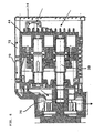
- FIG. 5 shows an enlarged view of the shaft bearing on the intermediate wall 18 and arranged on the bearing cover plate 42 shaft seal.
- the shaft bearing consists of a generally designated 50 double ball bearing.
- a recess 52 is formed in the bearing cover plate 42.
- a shaft seal 54 made of rubber-elastic material is arranged, which is sealingly abutting with a pointed sealing edge 54a on the outer circumference of a shrunk onto the shaft 32 sleeve 56.
- the sleeve 56 is sealed with a sealing ring 58 against the shaft 32.
- the sleeve 56 has a radially raised shoulder 56a, in which two sealing rings 60 are received axially adjacent to each other.
- the sealing rings 60 seal the sleeve 56 against the inner circumference of the recess in the bearing cover plate 42. Between the sealing ring 54 and the recess in the bearing cover plate 42 remains a gap 62 which communicates with a bore 64 in connection. The bore 64 leads through the bearing cover plate 42 to the outside.
- the peculiarity of the shaft seal shown in Figure 5 is that it is arranged on the bearing cover plate 42 and thus allows easy installation of the open end side of the housing base body ago.
- the main body of the housing is surrounded by a hood 70 which delimits axial cooling air passages 72 with the outer circumference of the housing.
- the cooling air channels 72 lead from a protective grid 74 adjacent to the housing cover 44 axially along the outer circumference of the housing to behind the gear chamber, where they open radially inwardly into a fan chamber 76, in which a fan is arranged, the rotor is mounted on a drive shaft, which with the lower shaft 30 is coupled.
- the cooling air exits radially downwards.
Claims (7)
- Machine de compression pourvue de deux rotors à rotation en sens inverse (26, 28) qui sont montés sur deux arbres (30, 32) parallèles, distants l'un de l'autre et logés dans un boîtier (12), l'un d'entre eux étant entraîné directement et l'autre par des roues dentées (34, 36) engrenant les unes dans les autres, disposées sur les arbres, étant précisé que- le boîtier (12) comporte deux parois (16, 18) radiales formées d'une seule partie l'une avec l'autre et avec une paroi périphérique, dans lesquelles sont logés les arbres (30, 32) et entre lesquelles sont disposées les roues dentées (34, 36), et une paroi latérale avec une ouverture (38) fermée par un couvercle (40) latéral amovible, et- une des parois radiales est une paroi extérieure radiale (16) et l'autre une paroi intermédiaire (18), qui du côté de la paroi extérieure radiale délimite une chambre d'engrenage (22) accueillant les roues dentées et de l'autre côté une chambre de travail (24) recevant les rotors (26, 28), caractérisée en ce que- la chambre de travail (24) est fermée du côté frontal opposé à la paroi intermédiaire (18) par un couvercle radial de boîtier (44);- le boîtier (12) forme un corps de base monobloc qui à son extrémité frontale tournée vers le couvercle de boîtier (44) comporte une ouverture dont la largeur est la plus grande de tous les passages et alésages axiaux situés à l'intérieur du boîtier (12), de sorte que ceux-ci sont accessibles à travers cette ouverture pour le traitement lorsque le corps de base est serré, et en ce que- la paroi intermédiaire (18) de son côté comporte des ouvertures axialement continues destinées à recevoir les paliers d'arbres, dont la largeur est supérieure à celle des alésages axiaux des paliers dans la paroi extérieure radiale (16).
- Machine de compression selon la revendication 1, caractérisée en ce que les rotors (26, 28) sont disposés en porte-à-faux sur les arbres (30, 32).
- Machine de compression selon la revendication 1 ou 2, caractérisée en ce que la chambre de travail (24) sur le côté frontal opposé à la paroi intermédiaire (18) est fermée par un couvercle de boîtier (44), dans lequel est formé un orifice de décharge, qui lors de la rotation des rotors (26, 28) est dégagé suite à une phase de compression interne et fermé par la face frontale d'un des rotors pendant une phase d'admission.
- Machine de compression selon l'une des revendications précédentes, caractérisée en ce qu'une plaque de chapeau de palier (42) est appliquée sur la paroi intermédiaire (18) du côté des rotors.
- Machine de compression selon la revendication 4, caractérisée en ce que la plaque de chapeau de palier (42) comporte des creux pour recevoir les joints d'étanchéité des arbres.
- Machine de compression selon l'une des revendications précédentes, caractérisée en ce qu'au couvercle radial de boîtier (44) est contigu un capot (70) qui entoure un ventilateur.
- Machine de compression selon l'une des revendications 1 à 5, caractérisée en ce que la paroi périphérique du boîtier (12) est entourée d'un capot (70) qui forme avec la paroi périphérique des canaux d'air de refroidissement (72), qui depuis la surface frontale adjacente au couvercle de boîtier (44) sont guidés jusqu'à un ventilateur lequel, sur le côté de la chambre d'engrenage (22) opposé à la chambre de travail (24), est disposé sur un arbre primaire.
Applications Claiming Priority (3)
| Application Number | Priority Date | Filing Date | Title |
|---|---|---|---|
| DE20216504U DE20216504U1 (de) | 2002-10-25 | 2002-10-25 | Verdrängermaschine mit gegensinnig laufenden Rotoren |
| DE20216504U | 2002-10-25 | ||
| PCT/EP2003/011853 WO2004038227A1 (fr) | 2002-10-25 | 2003-10-24 | Machine de compression pourvue de deux rotors a rotation en sens inverse |
Publications (2)
| Publication Number | Publication Date |
|---|---|
| EP1554496A1 EP1554496A1 (fr) | 2005-07-20 |
| EP1554496B1 true EP1554496B1 (fr) | 2006-06-07 |
Family
ID=7976350
Family Applications (1)
| Application Number | Title | Priority Date | Filing Date |
|---|---|---|---|
| EP03809330A Expired - Lifetime EP1554496B1 (fr) | 2002-10-25 | 2003-10-24 | Machine de compression pourvue de deux rotors a rotation en sens inverse |
Country Status (9)
| Country | Link |
|---|---|
| US (1) | US7128543B2 (fr) |
| EP (1) | EP1554496B1 (fr) |
| JP (1) | JP4148948B2 (fr) |
| KR (1) | KR100604734B1 (fr) |
| CN (1) | CN100489311C (fr) |
| AU (1) | AU2003276182A1 (fr) |
| DE (2) | DE20216504U1 (fr) |
| HK (1) | HK1086872A1 (fr) |
| WO (1) | WO2004038227A1 (fr) |
Families Citing this family (9)
| Publication number | Priority date | Publication date | Assignee | Title |
|---|---|---|---|---|
| JP4353837B2 (ja) * | 2004-03-22 | 2009-10-28 | 住友重機械工業株式会社 | 減速機及び減速機用摩擦負荷付与部材 |
| DE102006035783A1 (de) * | 2006-08-01 | 2008-02-07 | Grasso Gmbh Refrigeration Technology | Schraubenverdichter |
| TW200848617A (en) * | 2007-06-08 | 2008-12-16 | Jaguar Prec Industry Co Ltd | Motor direct drive air pump, related applications and manufacturing methods thereof |
| JP2010144576A (ja) * | 2008-12-17 | 2010-07-01 | Toyota Industries Corp | 電動ルーツ型圧縮機 |
| DE102008063983A1 (de) * | 2008-12-19 | 2010-07-01 | Dürr Systems GmbH | Pumpe zum Fördern eines Fluids, insbesondere Dosierpumpe |
| JP5504530B2 (ja) * | 2009-09-15 | 2014-05-28 | オリオン機械株式会社 | 回転ポンプ装置の製造方法 |
| CN103047049B (zh) * | 2012-12-31 | 2015-04-29 | 王来瑞 | 一种涡轮喷气发动机 |
| KR101586330B1 (ko) * | 2015-10-06 | 2016-01-19 | (주)한국브로워 | 초저음 무맥동의 특성을 가진 용적형 회전식 브로워 |
| CN109915365B (zh) * | 2019-04-04 | 2023-11-17 | 烟台东德氢能技术有限公司 | 罗茨式空气压缩机 |
Family Cites Families (14)
| Publication number | Priority date | Publication date | Assignee | Title |
|---|---|---|---|---|
| US1386792A (en) * | 1919-08-14 | 1921-08-09 | John T Needham | Rotary blower |
| US2188752A (en) * | 1938-01-12 | 1940-01-30 | Roots Connersville Blower Corp | Fluid handling apparatus |
| US2642808A (en) * | 1948-05-17 | 1953-06-23 | Waterous Co | Sanitary pump |
| US2635552A (en) * | 1949-01-31 | 1953-04-21 | Bump Pump Co | Sanitary pump assemblage |
| FR1480749A (fr) | 1966-05-23 | 1967-05-12 | Midland Ross Corp | Compresseur du type roots |
| US4057375A (en) * | 1976-10-22 | 1977-11-08 | Nachtrieb Paul W | Pump structure |
| EP0048095B1 (fr) | 1980-09-05 | 1983-12-14 | British Nuclear Fuels PLC | Pompe pour des gaz lourds |
| US4457680A (en) * | 1983-04-27 | 1984-07-03 | Paget Win W | Rotary compressor |
| US4772187A (en) * | 1986-09-08 | 1988-09-20 | Thompson George A | Rotary pump |
| GB9004594D0 (en) | 1990-02-28 | 1990-04-25 | Apv Crepaco Pumps Ltd | Improvements in or relating to rotary pumps |
| CN2299170Y (zh) * | 1996-11-08 | 1998-12-02 | 徐曦 | 单级爪式转子真空泵 |
| DE19819538C2 (de) * | 1998-04-30 | 2000-02-17 | Rietschle Werner Gmbh & Co Kg | Druck-Saug-Pumpe |
| DE29905249U1 (de) * | 1999-03-22 | 1999-12-30 | Rietschle Werner Gmbh & Co Kg | Pumpe zur Erzeugung von Druck und Unterdruck |
| US6729863B2 (en) * | 1999-03-22 | 2004-05-04 | Werner Rietschle Gmbh & Co. Kg | Rotary pump having high and low pressure ports in the housing cover |
-
2002
- 2002-10-25 DE DE20216504U patent/DE20216504U1/de not_active Expired - Lifetime
-
2003
- 2003-10-24 AU AU2003276182A patent/AU2003276182A1/en not_active Abandoned
- 2003-10-24 DE DE50303735T patent/DE50303735D1/de not_active Expired - Lifetime
- 2003-10-24 EP EP03809330A patent/EP1554496B1/fr not_active Expired - Lifetime
- 2003-10-24 JP JP2004545993A patent/JP4148948B2/ja not_active Expired - Fee Related
- 2003-10-24 US US10/532,532 patent/US7128543B2/en not_active Expired - Lifetime
- 2003-10-24 CN CNB2003801020426A patent/CN100489311C/zh not_active Expired - Fee Related
- 2003-10-24 WO PCT/EP2003/011853 patent/WO2004038227A1/fr active IP Right Grant
- 2003-10-24 KR KR1020057007134A patent/KR100604734B1/ko active IP Right Grant
-
2006
- 2006-06-14 HK HK06106818.1A patent/HK1086872A1/xx not_active IP Right Cessation
Also Published As
| Publication number | Publication date |
|---|---|
| HK1086872A1 (en) | 2006-09-29 |
| US20060051231A1 (en) | 2006-03-09 |
| CN1708648A (zh) | 2005-12-14 |
| JP4148948B2 (ja) | 2008-09-10 |
| US7128543B2 (en) | 2006-10-31 |
| EP1554496A1 (fr) | 2005-07-20 |
| DE50303735D1 (de) | 2006-07-20 |
| DE20216504U1 (de) | 2003-03-06 |
| JP2006504030A (ja) | 2006-02-02 |
| KR100604734B1 (ko) | 2006-07-28 |
| AU2003276182A1 (en) | 2004-05-13 |
| WO2004038227A1 (fr) | 2004-05-06 |
| KR20050071619A (ko) | 2005-07-07 |
| CN100489311C (zh) | 2009-05-20 |
Similar Documents
| Publication | Publication Date | Title |
|---|---|---|
| EP1554496B1 (fr) | Machine de compression pourvue de deux rotors a rotation en sens inverse | |
| DE3614144A1 (de) | Kreiselverdichter | |
| DE112013006437T5 (de) | Hermetischer Verdichter und Kältekreislaufvorrichtung vom Dampfkompressions-Typ mit einem derartigen hermetischen Verdichter | |
| WO2007128489A1 (fr) | Machine hydrodynamique | |
| DE602004000798T2 (de) | Vakuumpumpe | |
| WO2014135202A1 (fr) | Agencement de pompe à vide de véhicule automobile électrique | |
| DE102017104063B4 (de) | Elektrische Gerotorpumpe mit Steuerspiegel | |
| DE2731451B1 (de) | Fluessigkeitsringverdichter oder vakuumpumpe | |
| DE102014212920A1 (de) | Schaufelpumpe | |
| WO2008022726A1 (fr) | Compresseur ou pompe à vide monobloc à palettes rotatives, avec moteur synchrone à rotor à disque monté en porte-à-faux | |
| DE112018004132B4 (de) | Spiralkompressor | |
| DE10117373A1 (de) | Hydraulisches Pumpenaggregat | |
| DE69726630T2 (de) | Vakuumpumpen | |
| DE19945871A1 (de) | Schraubenpumpe, insbesondere Schraubenvakuumpumpe, mit zwei Pumpstufen | |
| DE10349752B4 (de) | Motorpumpenaggregat | |
| DE2913608C2 (de) | Drehkolbenartige Rotationskolbenmaschine | |
| DE4038704C2 (de) | Drehkolbenpumpe | |
| DE4038872A1 (de) | Luftgekuehlte rotationsmaschine | |
| WO2003031823A1 (fr) | Pompe a vide rotative a refoulement axial | |
| US2220095A (en) | Rotary fluid motor and the like | |
| EP1163450B1 (fr) | Pompe pour la generation de pression ou de depression | |
| DE3824686C2 (de) | Rotationskolbenmaschine der Gerotor-Bauart | |
| DE102006036439A1 (de) | Förderaggregat | |
| DE3240523A1 (de) | Fluegelzellenverdichter | |
| DE19942687C2 (de) | Drehschiebermaschine |
Legal Events
| Date | Code | Title | Description |
|---|---|---|---|
| PUAI | Public reference made under article 153(3) epc to a published international application that has entered the european phase |
Free format text: ORIGINAL CODE: 0009012 |
|
| 17P | Request for examination filed |
Effective date: 20050421 |
|
| AK | Designated contracting states |
Kind code of ref document: A1 Designated state(s): AT BE BG CH CY CZ DE DK EE ES FI FR GB GR HU IE IT LI LU MC NL PT RO SE SI SK TR |
|
| AX | Request for extension of the european patent |
Extension state: AL LT LV MK |
|
| GRAP | Despatch of communication of intention to grant a patent |
Free format text: ORIGINAL CODE: EPIDOSNIGR1 |
|
| DAX | Request for extension of the european patent (deleted) | ||
| RBV | Designated contracting states (corrected) |
Designated state(s): CH DE FR GB IT LI |
|
| GRAS | Grant fee paid |
Free format text: ORIGINAL CODE: EPIDOSNIGR3 |
|
| GRAA | (expected) grant |
Free format text: ORIGINAL CODE: 0009210 |
|
| AK | Designated contracting states |
Kind code of ref document: B1 Designated state(s): CH DE FR GB IT LI |
|
| PG25 | Lapsed in a contracting state [announced via postgrant information from national office to epo] |
Ref country code: IT Free format text: LAPSE BECAUSE OF FAILURE TO SUBMIT A TRANSLATION OF THE DESCRIPTION OR TO PAY THE FEE WITHIN THE PRESCRIBED TIME-LIMIT;WARNING: LAPSES OF ITALIAN PATENTS WITH EFFECTIVE DATE BEFORE 2007 MAY HAVE OCCURRED AT ANY TIME BEFORE 2007. THE CORRECT EFFECTIVE DATE MAY BE DIFFERENT FROM THE ONE RECORDED. Effective date: 20060607 |
|
| REG | Reference to a national code |
Ref country code: GB Ref legal event code: FG4D Free format text: NOT ENGLISH |
|
| REG | Reference to a national code |
Ref country code: CH Ref legal event code: EP |
|
| REF | Corresponds to: |
Ref document number: 50303735 Country of ref document: DE Date of ref document: 20060720 Kind code of ref document: P |
|
| REG | Reference to a national code |
Ref country code: CH Ref legal event code: NV Representative=s name: BUGNION S.A. |
|
| GBT | Gb: translation of ep patent filed (gb section 77(6)(a)/1977) |
Effective date: 20061023 |
|
| ET | Fr: translation filed | ||
| PLBE | No opposition filed within time limit |
Free format text: ORIGINAL CODE: 0009261 |
|
| STAA | Information on the status of an ep patent application or granted ep patent |
Free format text: STATUS: NO OPPOSITION FILED WITHIN TIME LIMIT |
|
| 26N | No opposition filed |
Effective date: 20070308 |
|
| PGFP | Annual fee paid to national office [announced via postgrant information from national office to epo] |
Ref country code: CH Payment date: 20131029 Year of fee payment: 11 |
|
| REG | Reference to a national code |
Ref country code: CH Ref legal event code: PL |
|
| PG25 | Lapsed in a contracting state [announced via postgrant information from national office to epo] |
Ref country code: LI Free format text: LAPSE BECAUSE OF NON-PAYMENT OF DUE FEES Effective date: 20141031 Ref country code: CH Free format text: LAPSE BECAUSE OF NON-PAYMENT OF DUE FEES Effective date: 20141031 |
|
| REG | Reference to a national code |
Ref country code: FR Ref legal event code: PLFP Year of fee payment: 13 |
|
| REG | Reference to a national code |
Ref country code: FR Ref legal event code: PLFP Year of fee payment: 14 |
|
| REG | Reference to a national code |
Ref country code: FR Ref legal event code: PLFP Year of fee payment: 15 |
|
| REG | Reference to a national code |
Ref country code: FR Ref legal event code: PLFP Year of fee payment: 16 |
|
| PGFP | Annual fee paid to national office [announced via postgrant information from national office to epo] |
Ref country code: DE Payment date: 20201028 Year of fee payment: 18 Ref country code: GB Payment date: 20201027 Year of fee payment: 18 Ref country code: IT Payment date: 20201023 Year of fee payment: 18 Ref country code: FR Payment date: 20201026 Year of fee payment: 18 |
|
| REG | Reference to a national code |
Ref country code: DE Ref legal event code: R119 Ref document number: 50303735 Country of ref document: DE |
|
| GBPC | Gb: european patent ceased through non-payment of renewal fee |
Effective date: 20211024 |
|
| PG25 | Lapsed in a contracting state [announced via postgrant information from national office to epo] |
Ref country code: GB Free format text: LAPSE BECAUSE OF NON-PAYMENT OF DUE FEES Effective date: 20211024 Ref country code: DE Free format text: LAPSE BECAUSE OF NON-PAYMENT OF DUE FEES Effective date: 20220503 |
|
| PG25 | Lapsed in a contracting state [announced via postgrant information from national office to epo] |
Ref country code: FR Free format text: LAPSE BECAUSE OF NON-PAYMENT OF DUE FEES Effective date: 20211031 |
|
| PG25 | Lapsed in a contracting state [announced via postgrant information from national office to epo] |
Ref country code: IT Free format text: LAPSE BECAUSE OF NON-PAYMENT OF DUE FEES Effective date: 20211024 |