EP1554496B1 - Compressor machine with two counter-rotating rotors - Google Patents
Compressor machine with two counter-rotating rotors Download PDFInfo
- Publication number
- EP1554496B1 EP1554496B1 EP03809330A EP03809330A EP1554496B1 EP 1554496 B1 EP1554496 B1 EP 1554496B1 EP 03809330 A EP03809330 A EP 03809330A EP 03809330 A EP03809330 A EP 03809330A EP 1554496 B1 EP1554496 B1 EP 1554496B1
- Authority
- EP
- European Patent Office
- Prior art keywords
- housing
- compressor machine
- wall
- rotors
- machine according
- Prior art date
- Legal status (The legal status is an assumption and is not a legal conclusion. Google has not performed a legal analysis and makes no representation as to the accuracy of the status listed.)
- Expired - Lifetime
Links
Images
Classifications
-
- F—MECHANICAL ENGINEERING; LIGHTING; HEATING; WEAPONS; BLASTING
- F04—POSITIVE - DISPLACEMENT MACHINES FOR LIQUIDS; PUMPS FOR LIQUIDS OR ELASTIC FLUIDS
- F04C—ROTARY-PISTON, OR OSCILLATING-PISTON, POSITIVE-DISPLACEMENT MACHINES FOR LIQUIDS; ROTARY-PISTON, OR OSCILLATING-PISTON, POSITIVE-DISPLACEMENT PUMPS
- F04C29/00—Component parts, details or accessories of pumps or pumping installations, not provided for in groups F04C18/00 - F04C28/00
- F04C29/0042—Driving elements, brakes, couplings, transmissions specially adapted for pumps
- F04C29/005—Means for transmitting movement from the prime mover to driven parts of the pump, e.g. clutches, couplings, transmissions
-
- F—MECHANICAL ENGINEERING; LIGHTING; HEATING; WEAPONS; BLASTING
- F04—POSITIVE - DISPLACEMENT MACHINES FOR LIQUIDS; PUMPS FOR LIQUIDS OR ELASTIC FLUIDS
- F04C—ROTARY-PISTON, OR OSCILLATING-PISTON, POSITIVE-DISPLACEMENT MACHINES FOR LIQUIDS; ROTARY-PISTON, OR OSCILLATING-PISTON, POSITIVE-DISPLACEMENT PUMPS
- F04C18/00—Rotary-piston pumps specially adapted for elastic fluids
- F04C18/08—Rotary-piston pumps specially adapted for elastic fluids of intermeshing-engagement type, i.e. with engagement of co-operating members similar to that of toothed gearing
- F04C18/12—Rotary-piston pumps specially adapted for elastic fluids of intermeshing-engagement type, i.e. with engagement of co-operating members similar to that of toothed gearing of other than internal-axis type
-
- F—MECHANICAL ENGINEERING; LIGHTING; HEATING; WEAPONS; BLASTING
- F04—POSITIVE - DISPLACEMENT MACHINES FOR LIQUIDS; PUMPS FOR LIQUIDS OR ELASTIC FLUIDS
- F04C—ROTARY-PISTON, OR OSCILLATING-PISTON, POSITIVE-DISPLACEMENT MACHINES FOR LIQUIDS; ROTARY-PISTON, OR OSCILLATING-PISTON, POSITIVE-DISPLACEMENT PUMPS
- F04C29/00—Component parts, details or accessories of pumps or pumping installations, not provided for in groups F04C18/00 - F04C28/00
- F04C29/04—Heating; Cooling; Heat insulation
Definitions
- the invention relates to a compressor machine with two counter-rotating rotors, which are mounted on two parallel, spaced-apart and mounted in a housing shafts, one of which is driven directly and the other by intermeshing, mounted on the shafts gears.
- Compressor machines with two oppositely rotating rotors can work as compressors or vacuum pumps.
- EP 1 163 450 A1 such a machine with claw-type rotor blades is known, which can generate both suction air and blown air and is particularly suitable for use in the field of paper processing. Due to the internal compression of such machines, significantly higher pressure ratios can be achieved than e.g. by means of a roots pump.
- By flying arrangement of the rotors in a pot-like housing a simple construction is achieved.
- the two waves coupling gear on the one hand and the shaft bearing on the other hand are arranged in separate housing parts, which must be exactly aligned and pinned.
- the cup-shaped housing receiving the rotors must be pinned exactly to the transmission housing. This results in the need to edit pin holes as accurately as possible from two different sides of a housing part. Inaccuracies lead to skewed shafts and thus increased bearing loads, gear noise and other malfunctions.
- US 2,635,552 A discloses a rotary pump for pumping liquids primarily from the food sector.
- the pump has two parallel shafts to each of which a rotor is mounted flying. It comprises a gear housing with a gear chamber for receiving gear wheels and a housing bolted to the gear housing with a working chamber for receiving the rotors. The bearing of the waves takes place in the end walls of the gear chamber.
- US 1,386,792 A discloses a rotary blower with a housing and two parallel shafts to each of which a rotor is mounted.
- a working chamber In the housing, a working chamber, a gear chamber and an air chamber therebetween are arranged.
- the working chamber is bounded on one side by a radial cover. The storage of the waves takes place in a transmission chamber limiting frontal outer wall and in the radial cover.
- the invention provides a compacting machine in which, despite simplified manufacture and a reduced number of parts, precise alignment of the shafts is ensured.
- the compressor machine according to the invention has two rotors running in opposite directions, which are mounted on two parallel, spaced-apart and mounted in a housing shafts. One of the waves is direct and the other by intermeshing waves Gears driven.
- the housing has two integral with each other and with a peripheral wall formed radial walls in which the shafts are mounted. Between these radial walls, the gears are arranged. A side wall of the housing has a closed by a removable lid opening. With the cover removed, the gears can be mounted on the shafts through this opening.
- the bearing bores for the shafts can be mounted and machined in the one-piece housing with a single set-up so that with minimal number of parts any cause of alignment errors is eliminated.
- the lid closing the opening in the side wall of the housing has no influence on the bearing of the shafts. It is a simple part that only has to close the opening and seal against oil leakage. It has been found that the so avoided even small misalignments leads to better efficiency and reduced running noise.
- one of the radial walls is a radial outer wall and the other an intermediate wall which delimits on its one side with the radial outer wall a gear housing receiving the gears and on its other side a rotor accommodating the working chamber.
- the compressor machine according to the invention is characterized in that the working chamber is closed on the side facing away from the intermediate wall end face by a radial housing cover; the housing forms a monobloc base body, which has an opening at its front end facing the housing cover, the width of which is the largest of all located in the interior of the housing axial passages and holes, so that they are accessible for processing through this opening in a clamping of the body are, and that the intermediate wall in turn has axially through openings for receiving Wellenlagem whose width is greater than that of the axial bearing bores in the radial outer wall.
- the compressor machine described here by way of example has rotors with claw-shaped rotor blades and can be operated both as a compressor and as a vacuum pump.
- an integrally molded housing body 12 is mounted with a flanged electric motor 14.
- the housing body 12 has two radial, parallel and spaced apart walls 16, 18 which are interconnected by a peripheral wall 20.
- the radial wall 16 forms an outer wall.
- the radial wall 18 forms an intermediate wall of the housing body 12 and defines a transmission chamber 22 formed between the walls 16, 18 from a working chamber 24 which receives two rotors 26, 28 with claw-like rotor blades.
- the rotor 26 is mounted in a floating manner on an axial end of a shaft 30, which is mounted in the radial walls 16, 18. The opposite axial end of the shaft 30 is coupled directly to the output shaft of the electric motor 14.
- the rotor 28 is mounted in a floating manner on an axial end of a second shaft 32, which is likewise mounted in the radial walls 16, 18.
- the shafts 30, 32 are parallel and spaced apart.
- the shafts 30, 32 are coupled together by two intermeshing, arranged in the gear chamber 22 gears 34, 36, so that they rotate synchronously and in opposite directions of rotation.
- the housing body 12 has a side wall with an opening 38 which can be closed by a lid 40 fitted from outside. This opening 38 is dimensioned so that when removed cover 40, the gears 34, 36 in the gear chamber 22 for mounting on the shafts 30, 32 can be introduced.
- a bearing cover plate 42 is attached to the intermediate wall 18. At its end remote from the bearing cover plate 42 axial end of the working chamber 24 is closed by a radial housing cover 44.
- a hood 46 To the housing cover 44 includes a hood 46, which encloses a coupled for example with the shaft 30 or having a third-party drive fan.
- the described compressor machine is preferably a so-called "claw compressor", ie a machine with claw-shaped rotor blades and with internal compression.
- Figure 4 shows three phases in the cycle of such a machine, namely at a) the beginning of the compression process, at b) the advanced compression process and at c) the phase of pushing out the compacted volume.
- the phase shown in Figure 4a) is preceded by the inlet phase, in which a common inlet chamber is filled, then divided into two Operakammem and finally merged into a common volume, which then undergoes the internal compression.
- An outlet port denoted by A is closed during rotation of the rotors during the phase of internal compression and during the inlet phase by one of the end faces of the lower rotor.
- the outlet opening A is released by the lower rotor, so that the compressed volume can be ejected through the outlet port A.
- This outlet opening leads axially through the housing cover 44 out of the working space of the compressor machine.
- FIG. 5 shows an enlarged view of the shaft bearing on the intermediate wall 18 and arranged on the bearing cover plate 42 shaft seal.
- the shaft bearing consists of a generally designated 50 double ball bearing.
- a recess 52 is formed in the bearing cover plate 42.
- a shaft seal 54 made of rubber-elastic material is arranged, which is sealingly abutting with a pointed sealing edge 54a on the outer circumference of a shrunk onto the shaft 32 sleeve 56.
- the sleeve 56 is sealed with a sealing ring 58 against the shaft 32.
- the sleeve 56 has a radially raised shoulder 56a, in which two sealing rings 60 are received axially adjacent to each other.
- the sealing rings 60 seal the sleeve 56 against the inner circumference of the recess in the bearing cover plate 42. Between the sealing ring 54 and the recess in the bearing cover plate 42 remains a gap 62 which communicates with a bore 64 in connection. The bore 64 leads through the bearing cover plate 42 to the outside.
- the peculiarity of the shaft seal shown in Figure 5 is that it is arranged on the bearing cover plate 42 and thus allows easy installation of the open end side of the housing base body ago.
- the main body of the housing is surrounded by a hood 70 which delimits axial cooling air passages 72 with the outer circumference of the housing.
- the cooling air channels 72 lead from a protective grid 74 adjacent to the housing cover 44 axially along the outer circumference of the housing to behind the gear chamber, where they open radially inwardly into a fan chamber 76, in which a fan is arranged, the rotor is mounted on a drive shaft, which with the lower shaft 30 is coupled.
- the cooling air exits radially downwards.
Description
Die Erfindung betrifft eine Verdichtermaschine mit zwei gegensinnig laufenden Rotoren, die auf zwei parallelen, voneinander beabstandeten und in einem Gehäuse gelagerten Wellen montiert sind, von denen eine direkt und die andere durch miteinander kämmende, auf den Wellen angebrachte Zahnräder angetrieben ist.The invention relates to a compressor machine with two counter-rotating rotors, which are mounted on two parallel, spaced-apart and mounted in a housing shafts, one of which is driven directly and the other by intermeshing, mounted on the shafts gears.
Verdichtermaschinen mit zwei gegensinnig rotierenden Rotoren können als Verdichter oder Vakuumpumpen arbeiten. Aus der EP 1 163 450 A1 ist eine solche Maschine mit klauenartigen Rotorflügeln bekannt, die sowohl Saugluft als auch Blasluft erzeugen kann und sich besonders für den Einsatz im Bereich der Papierverarbeitung eignet. Aufgrund der inneren Verdichtung derartiger Maschinen können deutlich höhere Druckverhältnisse erreicht werden als z.B. mittels einer Roots-Pumpe. Durch fliegende Anordnung der Rotoren in einem topfartigen Gehäuse wird ein einfacher Aufbau erreicht. Das die beiden Wellen koppelnde Getriebe einerseits und die Wellenlagerung andererseits sind jedoch in getrennten Gehäuseteilen angeordnet, die exakt miteinander ausgerichtet und verstiftet werden müssen. Ebenso muß das die Rotoren aufnehmende topfförmige Gehäuse exakt mit dem Getriebegehäuse verstiftet werden. Daraus ergibt sich die Notwendigkeit, Stiftbohrungen möglichst genau von zwei verschiedenen Seiten eines Gehäuseteils bearbeiten zu müssen. Ungenauigkeiten führen zu schiefstehenden Wellen und dadurch erhöhten Lagerbelastungen, Zahnradgeräuschen und anderen Fehlfunktionen.Compressor machines with two oppositely rotating rotors can work as compressors or vacuum pumps. From EP 1 163 450 A1, such a machine with claw-type rotor blades is known, which can generate both suction air and blown air and is particularly suitable for use in the field of paper processing. Due to the internal compression of such machines, significantly higher pressure ratios can be achieved than e.g. by means of a roots pump. By flying arrangement of the rotors in a pot-like housing a simple construction is achieved. However, the two waves coupling gear on the one hand and the shaft bearing on the other hand, however, are arranged in separate housing parts, which must be exactly aligned and pinned. Likewise, the cup-shaped housing receiving the rotors must be pinned exactly to the transmission housing. This results in the need to edit pin holes as accurately as possible from two different sides of a housing part. Inaccuracies lead to skewed shafts and thus increased bearing loads, gear noise and other malfunctions.
US 2,635,552 A offenbart eine Rotationspumpe zum Pumpen von Flüssigkeiten vornehmlich aus dem Lebensmittelbereich. Die Pumpe weist zwei parallele Wellen auf, an denen jeweils ein Rotor fliegend befestigt ist. Sie umfasst ein Getriebegehäuse mit einer Getriebekammer zur Aufnahme von Zahnrädern und eine an dem Getriebegehäuse angeschraubtes Arbeitsgehäuse mit einer Arbeitskammer zur Aufnahme der Rotoren. Die Lagerung der Wellen erfolgt in den Stirnwänden der Getriebekammer.US 2,635,552 A discloses a rotary pump for pumping liquids primarily from the food sector. The pump has two parallel shafts to each of which a rotor is mounted flying. It comprises a gear housing with a gear chamber for receiving gear wheels and a housing bolted to the gear housing with a working chamber for receiving the rotors. The bearing of the waves takes place in the end walls of the gear chamber.
US 1,386,792 A offenbart ein Rotationsgebläse mit einem Gehäuse und zwei parallelen Wellen, an denen jeweils ein Rotor befestigt ist. In dem Gehäuse sind eine Arbeitskammer, eine Getriebekammer und dazwischenliegend eine Luftkammer angeordnet. Die Arbeitskammer wird auf ihrer einen Seite durch einen radialen Deckel begrenzt. Die Lagerung der Wellen erfolgt in einer die Getriebekammer begrenzenden stirnseitigen Außenwand und in dem radialen Deckel.US 1,386,792 A discloses a rotary blower with a housing and two parallel shafts to each of which a rotor is mounted. In the housing, a working chamber, a gear chamber and an air chamber therebetween are arranged. The working chamber is bounded on one side by a radial cover. The storage of the waves takes place in a transmission chamber limiting frontal outer wall and in the radial cover.
Durch die Erfindung wird eine Verdichtermaschine geschaffen, bei der trotz vereinfachter Herstellung und verminderter Teilezahl eine präzise Ausrichtung der Wellen gewährleistet ist. Die erfindungsgemäße Verdichtermaschine hat zwei gegensinnig laufende Rotoren, die auf zwei parallelen, voneinander beabstandeten und in einem Gehäuse gelagerten Wellen montiert sind. Eine der Wellen ist direkt und die andere durch miteinander kämmende, auf den Wellen angebrachte Zahnräder angetrieben. Das Gehäuse hat zwei einteilig miteinander und mit einer Umfangswand ausgebildete radiale Wände, in denen die Wellen gelagert sind. Zwischen diesen radialen Wänden sind die Zahnräder angeordnet. Eine Seitenwand des Gehäuses hat eine durch einen abnehmbaren Deckel verschlossene Öffnung. Bei abgenommenem Deckel können durch diese Öffnung hindurch die Zahnräder auf den Wellen montiert werden. Die Lagerbohrungen für die Wellen können in dem einstückigen Gehäuse mit einer einzigen Aufspannung angebracht und bearbeitet werden, so daß bei minimaler Anzahl von Teilen jegliche Ursache von Ausrichtungsfehlern entfällt. Der die Öffnung in der Seitenwand des Gehäuses verschließende Deckel hat keinerlei Einfluß auf die Lagerung der Wellen. Er ist ein einfaches Teil, das lediglich die Öffnung verschließen und gegen Ölaustritt abdichten muß. Es hat sich gezeigt, dass die so ermöglichte Vermeidung selbst kleiner Fehlstellungen zu einem besseren Wirkungsgrad und verringertem Laufgeräusch führt.The invention provides a compacting machine in which, despite simplified manufacture and a reduced number of parts, precise alignment of the shafts is ensured. The compressor machine according to the invention has two rotors running in opposite directions, which are mounted on two parallel, spaced-apart and mounted in a housing shafts. One of the waves is direct and the other by intermeshing waves Gears driven. The housing has two integral with each other and with a peripheral wall formed radial walls in which the shafts are mounted. Between these radial walls, the gears are arranged. A side wall of the housing has a closed by a removable lid opening. With the cover removed, the gears can be mounted on the shafts through this opening. The bearing bores for the shafts can be mounted and machined in the one-piece housing with a single set-up so that with minimal number of parts any cause of alignment errors is eliminated. The lid closing the opening in the side wall of the housing has no influence on the bearing of the shafts. It is a simple part that only has to close the opening and seal against oil leakage. It has been found that the so avoided even small misalignments leads to better efficiency and reduced running noise.
Bei der erfindungsgemäßen Verdichtermaschine ist eine der radialen Wände eine radiale Außenwand und die andere eine Zwischenwand, die auf ihrer einen Seite mit der radialen Außenwand eine die Zahnräder aufnehmende Getriebekammer und auf ihrer anderen Seite eine die Rotoren aufnehmende Arbeitskammer abgrenzt. Die erfindungsgemäße Verdichtermaschine ist dadurch gekennzeichnet, dass die Arbeitskammer auf der von der Zwischenwand abgewandten Stirnseite durch einen radialen Gehäusedeckel verschlossen ist; das Gehäuse einen Monoblock-Grundkörper bildet, der an seinem dem Gehäusedeckel zugewandten Stirnende eine Öffnung aufweist, deren Weite die größte von allen im Inneren des Gehäuses gelegenen axialen Durchgängen und Bohrungen ist, so dass diese zur Bearbeitung durch diese Öffnung in einer Aufspannung des Grundkörpers zugänglich sind, und dass die Zwischenwand ihrerseits axial durchgehende Öffnungen zur Aufnahme von Wellenlagem aufweist, deren Weite größer ist als die der axialen Lagerbohrungen in der radialen Außenwand.In the compressor machine according to the invention, one of the radial walls is a radial outer wall and the other an intermediate wall which delimits on its one side with the radial outer wall a gear housing receiving the gears and on its other side a rotor accommodating the working chamber. The compressor machine according to the invention is characterized in that the working chamber is closed on the side facing away from the intermediate wall end face by a radial housing cover; the housing forms a monobloc base body, which has an opening at its front end facing the housing cover, the width of which is the largest of all located in the interior of the housing axial passages and holes, so that they are accessible for processing through this opening in a clamping of the body are, and that the intermediate wall in turn has axially through openings for receiving Wellenlagem whose width is greater than that of the axial bearing bores in the radial outer wall.
Weitere Merkmale und Vorteile der Erfindung ergeben sich aus der folgenden Beschreibung einer bevorzugten Ausführungsform und aus den beigefügten Zeichnungen. In den Zeichnungen zeigen:
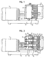
- Figur 1 eine Seitenansicht einer Verdichtermaschine;
- Figur 2 einen Axialschnitt der Verdichtermaschine;
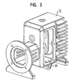
- Figur 3 eine Perspektivansicht eines einteiligen Gehäusekörpers der Verdichtermaschine;
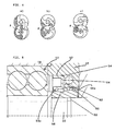
- Figur 4 drei Skizzen zur Veranschaulichung einer inneren Verdichtung;
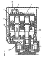
- Figur 5 eine vergrößerte Detailansicht einer Wellendichtung; und
- Figur 6 einen Axialschnitt einer alternativen Ausführungsform der Verdichtermaschine.
- Figure 1 is a side view of a compressor machine;
- FIG. 2 shows an axial section of the compressor machine;
- Figure 3 is a perspective view of a one-piece housing body of the compressor machine;
- Figure 4 shows three sketches illustrating an internal compression;
- Figure 5 is an enlarged detail view of a shaft seal; and
- Figure 6 is an axial section of an alternative embodiment of the compressor machine.
Die hier beispielshalber beschriebene Verdichtermaschine hat Rotoren mit klauenförmigen Rotorflügeln und kann sowohl als Verdichter als auch als Vakuumpumpe betrieben werden.The compressor machine described here by way of example has rotors with claw-shaped rotor blades and can be operated both as a compressor and as a vacuum pump.
Auf einem Sockel 10 ist ein einstückig geformter Gehäusekörper 12 mit einem angeflanschten Elektromotor 14 gelagert. Der Gehäusekörper 12 hat zwei radiale, parallele und voneinander beabstandete Wände 16, 18, die durch eine Umfangswand 20 miteinander verbunden sind. Die radiale Wand 16 bildet eine Außenwand. Die radiale Wand 18 bildet eine Zwischenwand des Gehäusekörpers 12 und grenzt einen zwischen den Wänden 16, 18 gebildeten Getrieberaum 22 von einer Arbeitskammer 24 ab, die zwei Rotoren 26, 28 mit klauenartigen Rotorflügeln aufnimmt. Der Rotor 26 ist fliegend an einem axialen Ende einer Welle 30 angebracht, die in den radialen Wänden 16, 18 gelagert ist. Das entgegengesetzte axiale Ende der Welle 30 ist direkt an die Abtriebswelle des Elektromotors 14 angekoppelt. Der Rotor 28 ist fliegend an einem axialen Ende einer zweiten Welle 32 angebracht, die ebenfalls in den radialen Wänden 16, 18 gelagert ist. Die Wellen 30, 32 sind parallel und voneinander beabstandet. Die Wellen 30, 32 sind durch zwei miteinander kämmende, im Getrieberaum 22 angeordnete Zahnräder 34, 36 miteinander gekoppelt, so daß sie synchron und mit entgegengesetztem Drehsinn rotieren.On a
Der Gehäusekörper 12 hat eine Seitenwand mit einer Öffnung 38, die durch einen von außen aufgesetzten Deckel 40 verschließbar ist. Diese Öffnung 38 ist so bemessen, daß bei abgenommenem Deckel 40 die Zahnräder 34, 36 in den Getrieberaum 22 zur Montage auf den Wellen 30, 32 eingebracht werden können.The
Auf der Seite der Arbeitskammer 24 ist an die Zwischenwand 18 eine Lagerdeckelplatte 42 angesetzt. An ihrem von der Lagerdeckelplatte 42 abgewandten axialen Ende ist die Arbeitskammer 24 durch einen radialen Gehäusedeckel 44 verschlossen. An den Gehäusedeckel 44 schließt eine Haube 46 an, die einen beispielsweise mit der Welle 30 gekoppelten oder über einen Fremdantrieb verfügenden Lüfter umschließt.On the side of the working chamber 24, a
Bei der beschriebenen Verdichtermaschine handelt es sich vorzugsweise um einen sog. "Klauenverdichter", also eine Maschine mit klauenförmigen Rotorflügeln und mit innerer Verdichtung. Die Figur 4 zeigt drei Phasen im Zyklus einer solchen Maschine, nämlich bei a) den beginnenden Verdichtungsprozeß, bei b) den fortgeschrittenen Verdichtungsprozeß und bei c) die Phase des Ausschiebens des verdichteten Volumens. Der in Figur 4a) gezeigten Phase geht die Einlaßphase voraus, bei der eine gemeinsame Einlaßkammer aufgefüllt, dann in zwei Teilkammem aufgeteilt und schließlich zu einem gemeinsamen Volumen zusammengeführt wird, das dann die innere Verdichtung erfährt. Eine mit A bezeichnete Auslaßöffnung wird bei der Drehung der Rotoren während der Phase der inneren Verdichtung und während der Einlaßphase durch eine der Stirnflächen des unteren Rotors verschlossen. Beginnend mit dem in Figur 4b) gezeigten Zustand wird die Auslaßöffnung A durch den unteren Rotor freigegeben, damit das verdichtete Volumen über die Auslaßöffnung A ausgeschoben werden kann. Diese Auslaßöffnung führt axial durch den Gehäusedeckel 44 aus dem Arbeitsraum der Verdichtermaschine hinaus.The described compressor machine is preferably a so-called "claw compressor", ie a machine with claw-shaped rotor blades and with internal compression. Figure 4 shows three phases in the cycle of such a machine, namely at a) the beginning of the compression process, at b) the advanced compression process and at c) the phase of pushing out the compacted volume. The phase shown in Figure 4a) is preceded by the inlet phase, in which a common inlet chamber is filled, then divided into two Teilkammem and finally merged into a common volume, which then undergoes the internal compression. An outlet port denoted by A is closed during rotation of the rotors during the phase of internal compression and during the inlet phase by one of the end faces of the lower rotor. Starting with the state shown in Figure 4b), the outlet opening A is released by the lower rotor, so that the compressed volume can be ejected through the outlet port A. This outlet opening leads axially through the
Figur 5 zeigt in vergrößerter Darstellung die Wellenlagerung an der Zwischenwand 18 und die an der Lagerdeckelplatte 42 angeordnete Wellendichtung. Die Wellenlagerung besteht aus einem allgemein mit 50 bezeichneten Doppelkugellager. Zur Aufnahme der Wellendichtung ist in der Lagerdeckelplatte 42 eine Ausnehmung 52 gebildet. In der Ausnehmung 52 ist ein Wellendichtring 54 aus gummielastischem Material angeordnet, der mit einer spitzen Dichtkante 54a am Außenumfang einer auf der Welle 32 aufgeschrumpften Hülse 56 dichtend in Anlage ist. Die Hülse 56 ist mit einem Dichtring 58 gegen die Welle 32 abgedichtet. Die Hülse 56 hat eine radial überhöhte Schulter 56a, in der zwei Dichtringe 60 axial nebeneinander aufgenommen sind. Die Dichtringe 60 dichten die Hülse 56 gegen den Innenumfang der Ausnehmung in der Lagerdeckelplatte 42 ab. Zwischen dem Dichtring 54 und der Aussparung in der Lagerdeckelplatte 42 verbleibt ein Zwischenraum 62, der mit einer Bohrung 64 in Verbindung steht. Die Bohrung 64 führt durch die Lagerdeckelplatte 42 nach außen.Figure 5 shows an enlarged view of the shaft bearing on the
Die Besonderheit der in Figur 5 dargestellten Wellendichtung besteht darin, daß sie an der Lagerdeckelplatte 42 angeordnet ist und so einen problemlosen Einbau von der offenen Stirnseite des Gehäusegrundkörpers her ermöglicht.The peculiarity of the shaft seal shown in Figure 5 is that it is arranged on the bearing
Bei der in Figur 6 gezeigten Ausführungsform der Verdichtermaschine ist der Grundkörper des Gehäuses von einer Haube 70 umgeben, die mit dem Außenumfang des Gehäuses axiale Kühlluftkanäle 72 abgrenzt. Die Kühlluftkanäle 72 führen von einem Schutzgitter 74 neben dem Gehäusedeckel 44 axial entlang dem Außenumfang des Gehäuses bis hinter die Getriebekammer, wo sie radial einwärts in eine Lüfterkammer 76 münden, in der ein Lüfter angeordnet ist, dessen Läufer auf einer Antriebswelle befestigt ist, die mit der unteren Welle 30 gekoppelt ist. Die Kühlluft tritt radial nach unten aus.In the embodiment of the compressor machine shown in FIG. 6, the main body of the housing is surrounded by a
Claims (7)
- Compressor machine with two counter-rotating rotors (26, 28) which are mounted on two parallel, spaced shafts (30, 32) supported in a housing (12), one of which being driven directly and the other one by combing cogwheels (34, 36) mounted on the shafts, wherein- the housing (12) has two radial walls (16, 18) constructed in one-piece with each other and with a peripheral wall, in which the shafts (30, 32) are supported and between which the cogwheels (34, 36) are arranged, and a side wall comprising an opening (38) closed by a detachable side lid (40), and- one of the radial walls is a radial outer wall (16) and the other one an intermediate wall (18), which with the radial outer wall defines a gearbox (22) accommodating the cogwheels on its one side and a working chamber (24) accommodating the rotors (26, 28) on its other side,characterized in that- the working chamber (24) is closed by a radial housing lid (44) on the front turned away from the intermediate wall (18);- the housing (12) forms a monoblock base body having an opening on the front end turned towards the housing lid (44), the extent of which is the largest of all axial passageways and boreholes inside the housing (12), so that they are accessible by this opening in a clamping of the base body, and that- the intermediate wall (18) on its part has axially continuous openings for accommodating shaft bearings the width of which is larger than the width of the axial bores of the bearings in the radial outer wall (16).
- Compressor machine according to claim 1, characterized in that the rotors (26, 28) are over-mounted at the shafts (30, 32).
- Compressor machine according to claim 1 or 2, characterized in that the working chamber (24) is closed by a housing lid (44) on the front turned away from the intermediate wall (18), in which an outlet port is formed which, following a phase of inner compression, is laid open when the rotors (26, 28) are turned and closed by the front plane of one of the rotors during an intake phase.
- Compressor machine according to one of the preceding claims, characterized in that a bearing lid plate (42) is affixed to the intermediate wall (18) on the side of the rotors.
- Compressor machine according to claim 4, characterized in that the bearing lid plate (42) comprises recesses for accommodating the shaft sealings.
- Compressor machine according to one of the preceding claims, characterized in that a hood (70) surrounding the ventilator is connected to the radial housing lid (44).
- Compressor machine according to one of claims 1 to 5, characterized in that the peripheral wall of the housing (12) is surrounded by a hood (70) forming axial cooling air channels (72) with the peripheral wall which are lead from the front plane neighboring the housing lid (44) to a ventilator arranged on a driveshaft on the side of the shaft chamber (22) turned away from the working chamber (24).
Applications Claiming Priority (3)
| Application Number | Priority Date | Filing Date | Title |
|---|---|---|---|
| DE20216504U DE20216504U1 (en) | 2002-10-25 | 2002-10-25 | Displacement machine with rotors running in opposite directions |
| DE20216504U | 2002-10-25 | ||
| PCT/EP2003/011853 WO2004038227A1 (en) | 2002-10-25 | 2003-10-24 | Compressor machine with two counter-rotating rotors |
Publications (2)
| Publication Number | Publication Date |
|---|---|
| EP1554496A1 EP1554496A1 (en) | 2005-07-20 |
| EP1554496B1 true EP1554496B1 (en) | 2006-06-07 |
Family
ID=7976350
Family Applications (1)
| Application Number | Title | Priority Date | Filing Date |
|---|---|---|---|
| EP03809330A Expired - Lifetime EP1554496B1 (en) | 2002-10-25 | 2003-10-24 | Compressor machine with two counter-rotating rotors |
Country Status (9)
| Country | Link |
|---|---|
| US (1) | US7128543B2 (en) |
| EP (1) | EP1554496B1 (en) |
| JP (1) | JP4148948B2 (en) |
| KR (1) | KR100604734B1 (en) |
| CN (1) | CN100489311C (en) |
| AU (1) | AU2003276182A1 (en) |
| DE (2) | DE20216504U1 (en) |
| HK (1) | HK1086872A1 (en) |
| WO (1) | WO2004038227A1 (en) |
Families Citing this family (9)
| Publication number | Priority date | Publication date | Assignee | Title |
|---|---|---|---|---|
| JP4353837B2 (en) * | 2004-03-22 | 2009-10-28 | 住友重機械工業株式会社 | Reducer and friction load applying member for reducer |
| DE102006035783A1 (en) * | 2006-08-01 | 2008-02-07 | Grasso Gmbh Refrigeration Technology | screw compressors |
| TW200848617A (en) * | 2007-06-08 | 2008-12-16 | Jaguar Prec Industry Co Ltd | Motor direct drive air pump, related applications and manufacturing methods thereof |
| JP2010144576A (en) * | 2008-12-17 | 2010-07-01 | Toyota Industries Corp | Electric roots compressor |
| DE102008063983A1 (en) * | 2008-12-19 | 2010-07-01 | Dürr Systems GmbH | Pump for conveying a fluid, in particular metering pump |
| JP5504530B2 (en) * | 2009-09-15 | 2014-05-28 | オリオン機械株式会社 | Manufacturing method of rotary pump device |
| CN103047049B (en) * | 2012-12-31 | 2015-04-29 | 王来瑞 | Turbojet engine |
| KR101586330B1 (en) * | 2015-10-06 | 2016-01-19 | (주)한국브로워 | Helical port roots type rotary blower |
| CN109915365B (en) * | 2019-04-04 | 2023-11-17 | 烟台东德氢能技术有限公司 | Roots type air compressor |
Family Cites Families (14)
| Publication number | Priority date | Publication date | Assignee | Title |
|---|---|---|---|---|
| US1386792A (en) * | 1919-08-14 | 1921-08-09 | John T Needham | Rotary blower |
| US2188752A (en) * | 1938-01-12 | 1940-01-30 | Roots Connersville Blower Corp | Fluid handling apparatus |
| US2642808A (en) | 1948-05-17 | 1953-06-23 | Waterous Co | Sanitary pump |
| US2635552A (en) * | 1949-01-31 | 1953-04-21 | Bump Pump Co | Sanitary pump assemblage |
| FR1480749A (en) * | 1966-05-23 | 1967-05-12 | Midland Ross Corp | Roots type compressor |
| US4057375A (en) * | 1976-10-22 | 1977-11-08 | Nachtrieb Paul W | Pump structure |
| DE3161646D1 (en) | 1980-09-05 | 1984-01-19 | British Nuclear Fuels Plc | Pump for heavy gases |
| US4457680A (en) * | 1983-04-27 | 1984-07-03 | Paget Win W | Rotary compressor |
| US4772187A (en) * | 1986-09-08 | 1988-09-20 | Thompson George A | Rotary pump |
| GB9004594D0 (en) * | 1990-02-28 | 1990-04-25 | Apv Crepaco Pumps Ltd | Improvements in or relating to rotary pumps |
| CN2299170Y (en) * | 1996-11-08 | 1998-12-02 | 徐曦 | Single-stage claw rotor vacuum pump |
| DE19819538C2 (en) * | 1998-04-30 | 2000-02-17 | Rietschle Werner Gmbh & Co Kg | Pressure suction pump |
| DE29905249U1 (en) | 1999-03-22 | 1999-12-30 | Rietschle Werner Gmbh & Co Kg | Pump for generating pressure and negative pressure |
| US6729863B2 (en) | 1999-03-22 | 2004-05-04 | Werner Rietschle Gmbh & Co. Kg | Rotary pump having high and low pressure ports in the housing cover |
-
2002
- 2002-10-25 DE DE20216504U patent/DE20216504U1/en not_active Expired - Lifetime
-
2003
- 2003-10-24 JP JP2004545993A patent/JP4148948B2/en not_active Expired - Fee Related
- 2003-10-24 EP EP03809330A patent/EP1554496B1/en not_active Expired - Lifetime
- 2003-10-24 US US10/532,532 patent/US7128543B2/en not_active Expired - Lifetime
- 2003-10-24 CN CNB2003801020426A patent/CN100489311C/en not_active Expired - Fee Related
- 2003-10-24 WO PCT/EP2003/011853 patent/WO2004038227A1/en active IP Right Grant
- 2003-10-24 AU AU2003276182A patent/AU2003276182A1/en not_active Abandoned
- 2003-10-24 DE DE50303735T patent/DE50303735D1/en not_active Expired - Lifetime
- 2003-10-24 KR KR1020057007134A patent/KR100604734B1/en active IP Right Grant
-
2006
- 2006-06-14 HK HK06106818.1A patent/HK1086872A1/en not_active IP Right Cessation
Also Published As
| Publication number | Publication date |
|---|---|
| CN100489311C (en) | 2009-05-20 |
| CN1708648A (en) | 2005-12-14 |
| US20060051231A1 (en) | 2006-03-09 |
| AU2003276182A1 (en) | 2004-05-13 |
| WO2004038227A1 (en) | 2004-05-06 |
| JP4148948B2 (en) | 2008-09-10 |
| US7128543B2 (en) | 2006-10-31 |
| KR100604734B1 (en) | 2006-07-28 |
| HK1086872A1 (en) | 2006-09-29 |
| EP1554496A1 (en) | 2005-07-20 |
| JP2006504030A (en) | 2006-02-02 |
| DE20216504U1 (en) | 2003-03-06 |
| KR20050071619A (en) | 2005-07-07 |
| DE50303735D1 (en) | 2006-07-20 |
Similar Documents
| Publication | Publication Date | Title |
|---|---|---|
| EP1554496B1 (en) | Compressor machine with two counter-rotating rotors | |
| DE3614144A1 (en) | CENTRIFUGAL COMPRESSORS | |
| DE112013006437T5 (en) | Hermetic compressor and vapor compression type refrigeration cycle device with such a hermetic compressor | |
| WO2007128489A1 (en) | Hydrodynamic machine | |
| DE602004000798T2 (en) | vacuum pump | |
| WO2014135202A1 (en) | Electric motor vehicle vacuum pump arrangement | |
| DE102017104063B4 (en) | Electric gerotor pump with control mirror | |
| DE2731451B1 (en) | Liquid ring compressor or vacuum pump | |
| DE102014212920A1 (en) | showel | |
| WO2008022726A1 (en) | Rotating-slide vacuum pump or compressor of block design having a disc-rotor synchronous motor which is mounted on flying bearings | |
| DE112018004132B4 (en) | Scroll compressor | |
| DE10117373A1 (en) | Hydraulic pump unit | |
| DE69726630T2 (en) | vacuum pumps | |
| DE10349752B4 (en) | A motor pump assembly | |
| DE19945871A1 (en) | Screw pump, in particular screw vacuum pump, with two pump stages | |
| DE4038704C2 (en) | Rotary lobe pump | |
| DE4038872A1 (en) | Air-cooled rotary exhauster or compressor - incorporates two=part sound dampening cowl leaving intervening space surrounding compressor housing | |
| WO2003031823A1 (en) | Axially discharging friction vacuum pump | |
| US2220095A (en) | Rotary fluid motor and the like | |
| EP1163450B1 (en) | Pump for generating pressure or negative pressure | |
| DE3824686C2 (en) | Rotary piston machine of the gerotor type | |
| DE102006036439A1 (en) | Conveying unit e.g. roller vane pump, has pressure channel loading rear groove chamber with pressure at outlet during zero to five degree rotation of rotor from point of time at which working chamber is not connected with inlet | |
| DE3240523A1 (en) | Vane-cell compressor | |
| DE19942687C2 (en) | Rotary vane engine | |
| DE102007030199A1 (en) | Screw spindle pump, to impel and compress gases, has an oil flow from an oil pump to the cogwheel teeth of the gearing |
Legal Events
| Date | Code | Title | Description |
|---|---|---|---|
| PUAI | Public reference made under article 153(3) epc to a published international application that has entered the european phase |
Free format text: ORIGINAL CODE: 0009012 |
|
| 17P | Request for examination filed |
Effective date: 20050421 |
|
| AK | Designated contracting states |
Kind code of ref document: A1 Designated state(s): AT BE BG CH CY CZ DE DK EE ES FI FR GB GR HU IE IT LI LU MC NL PT RO SE SI SK TR |
|
| AX | Request for extension of the european patent |
Extension state: AL LT LV MK |
|
| GRAP | Despatch of communication of intention to grant a patent |
Free format text: ORIGINAL CODE: EPIDOSNIGR1 |
|
| DAX | Request for extension of the european patent (deleted) | ||
| RBV | Designated contracting states (corrected) |
Designated state(s): CH DE FR GB IT LI |
|
| GRAS | Grant fee paid |
Free format text: ORIGINAL CODE: EPIDOSNIGR3 |
|
| GRAA | (expected) grant |
Free format text: ORIGINAL CODE: 0009210 |
|
| AK | Designated contracting states |
Kind code of ref document: B1 Designated state(s): CH DE FR GB IT LI |
|
| PG25 | Lapsed in a contracting state [announced via postgrant information from national office to epo] |
Ref country code: IT Free format text: LAPSE BECAUSE OF FAILURE TO SUBMIT A TRANSLATION OF THE DESCRIPTION OR TO PAY THE FEE WITHIN THE PRESCRIBED TIME-LIMIT;WARNING: LAPSES OF ITALIAN PATENTS WITH EFFECTIVE DATE BEFORE 2007 MAY HAVE OCCURRED AT ANY TIME BEFORE 2007. THE CORRECT EFFECTIVE DATE MAY BE DIFFERENT FROM THE ONE RECORDED. Effective date: 20060607 |
|
| REG | Reference to a national code |
Ref country code: GB Ref legal event code: FG4D Free format text: NOT ENGLISH |
|
| REG | Reference to a national code |
Ref country code: CH Ref legal event code: EP |
|
| REF | Corresponds to: |
Ref document number: 50303735 Country of ref document: DE Date of ref document: 20060720 Kind code of ref document: P |
|
| REG | Reference to a national code |
Ref country code: CH Ref legal event code: NV Representative=s name: BUGNION S.A. |
|
| GBT | Gb: translation of ep patent filed (gb section 77(6)(a)/1977) |
Effective date: 20061023 |
|
| ET | Fr: translation filed | ||
| PLBE | No opposition filed within time limit |
Free format text: ORIGINAL CODE: 0009261 |
|
| STAA | Information on the status of an ep patent application or granted ep patent |
Free format text: STATUS: NO OPPOSITION FILED WITHIN TIME LIMIT |
|
| 26N | No opposition filed |
Effective date: 20070308 |
|
| PGFP | Annual fee paid to national office [announced via postgrant information from national office to epo] |
Ref country code: CH Payment date: 20131029 Year of fee payment: 11 |
|
| REG | Reference to a national code |
Ref country code: CH Ref legal event code: PL |
|
| PG25 | Lapsed in a contracting state [announced via postgrant information from national office to epo] |
Ref country code: LI Free format text: LAPSE BECAUSE OF NON-PAYMENT OF DUE FEES Effective date: 20141031 Ref country code: CH Free format text: LAPSE BECAUSE OF NON-PAYMENT OF DUE FEES Effective date: 20141031 |
|
| REG | Reference to a national code |
Ref country code: FR Ref legal event code: PLFP Year of fee payment: 13 |
|
| REG | Reference to a national code |
Ref country code: FR Ref legal event code: PLFP Year of fee payment: 14 |
|
| REG | Reference to a national code |
Ref country code: FR Ref legal event code: PLFP Year of fee payment: 15 |
|
| REG | Reference to a national code |
Ref country code: FR Ref legal event code: PLFP Year of fee payment: 16 |
|
| PGFP | Annual fee paid to national office [announced via postgrant information from national office to epo] |
Ref country code: DE Payment date: 20201028 Year of fee payment: 18 Ref country code: GB Payment date: 20201027 Year of fee payment: 18 Ref country code: IT Payment date: 20201023 Year of fee payment: 18 Ref country code: FR Payment date: 20201026 Year of fee payment: 18 |
|
| REG | Reference to a national code |
Ref country code: DE Ref legal event code: R119 Ref document number: 50303735 Country of ref document: DE |
|
| GBPC | Gb: european patent ceased through non-payment of renewal fee |
Effective date: 20211024 |
|
| PG25 | Lapsed in a contracting state [announced via postgrant information from national office to epo] |
Ref country code: GB Free format text: LAPSE BECAUSE OF NON-PAYMENT OF DUE FEES Effective date: 20211024 Ref country code: DE Free format text: LAPSE BECAUSE OF NON-PAYMENT OF DUE FEES Effective date: 20220503 |
|
| PG25 | Lapsed in a contracting state [announced via postgrant information from national office to epo] |
Ref country code: FR Free format text: LAPSE BECAUSE OF NON-PAYMENT OF DUE FEES Effective date: 20211031 |
|
| PG25 | Lapsed in a contracting state [announced via postgrant information from national office to epo] |
Ref country code: IT Free format text: LAPSE BECAUSE OF NON-PAYMENT OF DUE FEES Effective date: 20211024 |