EP1554224B1 - Verfahren und maschine zur herstellung von asymmetrischen konvexen glasscheiben - Google Patents
Verfahren und maschine zur herstellung von asymmetrischen konvexen glasscheiben Download PDFInfo
- Publication number
- EP1554224B1 EP1554224B1 EP03807881A EP03807881A EP1554224B1 EP 1554224 B1 EP1554224 B1 EP 1554224B1 EP 03807881 A EP03807881 A EP 03807881A EP 03807881 A EP03807881 A EP 03807881A EP 1554224 B1 EP1554224 B1 EP 1554224B1
- Authority
- EP
- European Patent Office
- Prior art keywords
- blowing
- bending
- glass sheets
- sheets
- air
- Prior art date
- Legal status (The legal status is an assumption and is not a legal conclusion. Google has not performed a legal analysis and makes no representation as to the accuracy of the status listed.)
- Expired - Lifetime
Links
- 239000011521 glass Substances 0.000 title claims abstract description 80
- 238000000034 method Methods 0.000 title claims abstract description 34
- 238000007664 blowing Methods 0.000 claims abstract description 78
- 238000005452 bending Methods 0.000 claims abstract description 63
- 238000004519 manufacturing process Methods 0.000 claims abstract description 7
- 238000007493 shaping process Methods 0.000 claims description 33
- XLYOFNOQVPJJNP-UHFFFAOYSA-N water Substances O XLYOFNOQVPJJNP-UHFFFAOYSA-N 0.000 claims description 4
- 238000001816 cooling Methods 0.000 claims description 2
- 238000010438 heat treatment Methods 0.000 claims description 2
- 230000001747 exhibiting effect Effects 0.000 claims 3
- 238000003491 array Methods 0.000 claims 1
- 238000006073 displacement reaction Methods 0.000 abstract 1
- 238000010791 quenching Methods 0.000 description 6
- 241001639412 Verres Species 0.000 description 3
- 238000000465 moulding Methods 0.000 description 3
- 229920000297 Rayon Polymers 0.000 description 2
- 230000000694 effects Effects 0.000 description 2
- 238000003825 pressing Methods 0.000 description 2
- 230000000171 quenching effect Effects 0.000 description 2
- 239000002964 rayon Substances 0.000 description 2
- 238000003303 reheating Methods 0.000 description 2
- 238000005496 tempering Methods 0.000 description 2
- 238000011144 upstream manufacturing Methods 0.000 description 2
- 241001415961 Gaviidae Species 0.000 description 1
- 230000002301 combined effect Effects 0.000 description 1
- 238000010586 diagram Methods 0.000 description 1
- 238000009826 distribution Methods 0.000 description 1
- 239000012530 fluid Substances 0.000 description 1
- 230000005484 gravity Effects 0.000 description 1
- 238000005259 measurement Methods 0.000 description 1
- 238000012986 modification Methods 0.000 description 1
- 230000004048 modification Effects 0.000 description 1
- 230000003287 optical effect Effects 0.000 description 1
- 239000007787 solid Substances 0.000 description 1
- 239000005341 toughened glass Substances 0.000 description 1
- 238000004804 winding Methods 0.000 description 1
Images


Classifications
-
- C—CHEMISTRY; METALLURGY
- C03—GLASS; MINERAL OR SLAG WOOL
- C03B—MANUFACTURE, SHAPING, OR SUPPLEMENTARY PROCESSES
- C03B23/00—Re-forming shaped glass
- C03B23/02—Re-forming glass sheets
- C03B23/023—Re-forming glass sheets by bending
- C03B23/035—Re-forming glass sheets by bending using a gas cushion or by changing gas pressure, e.g. by applying vacuum or blowing for supporting the glass while bending
- C03B23/0352—Re-forming glass sheets by bending using a gas cushion or by changing gas pressure, e.g. by applying vacuum or blowing for supporting the glass while bending by suction or blowing out for providing the deformation force to bend the glass sheet
- C03B23/0355—Re-forming glass sheets by bending using a gas cushion or by changing gas pressure, e.g. by applying vacuum or blowing for supporting the glass while bending by suction or blowing out for providing the deformation force to bend the glass sheet by blowing without suction directly on the glass sheet
-
- C—CHEMISTRY; METALLURGY
- C03—GLASS; MINERAL OR SLAG WOOL
- C03B—MANUFACTURE, SHAPING, OR SUPPLEMENTARY PROCESSES
- C03B23/00—Re-forming shaped glass
- C03B23/02—Re-forming glass sheets
- C03B23/023—Re-forming glass sheets by bending
- C03B23/025—Re-forming glass sheets by bending by gravity
-
- C—CHEMISTRY; METALLURGY
- C03—GLASS; MINERAL OR SLAG WOOL
- C03B—MANUFACTURE, SHAPING, OR SUPPLEMENTARY PROCESSES
- C03B23/00—Re-forming shaped glass
- C03B23/02—Re-forming glass sheets
- C03B23/023—Re-forming glass sheets by bending
- C03B23/025—Re-forming glass sheets by bending by gravity
- C03B23/0252—Re-forming glass sheets by bending by gravity by gravity only, e.g. sagging
- C03B23/0254—Re-forming glass sheets by bending by gravity by gravity only, e.g. sagging in a continuous way, e.g. gravity roll bending
-
- C—CHEMISTRY; METALLURGY
- C03—GLASS; MINERAL OR SLAG WOOL
- C03B—MANUFACTURE, SHAPING, OR SUPPLEMENTARY PROCESSES
- C03B23/00—Re-forming shaped glass
- C03B23/02—Re-forming glass sheets
- C03B23/023—Re-forming glass sheets by bending
- C03B23/025—Re-forming glass sheets by bending by gravity
- C03B23/0256—Gravity bending accelerated by applying mechanical forces, e.g. inertia, weights or local forces
-
- C—CHEMISTRY; METALLURGY
- C03—GLASS; MINERAL OR SLAG WOOL
- C03B—MANUFACTURE, SHAPING, OR SUPPLEMENTARY PROCESSES
- C03B27/00—Tempering or quenching glass products
- C03B27/04—Tempering or quenching glass products using gas
- C03B27/0404—Nozzles, blow heads, blowing units or their arrangements, specially adapted for flat or bent glass sheets
- C03B27/0408—Nozzles, blow heads, blowing units or their arrangements, specially adapted for flat or bent glass sheets being dismountable
-
- C—CHEMISTRY; METALLURGY
- C03—GLASS; MINERAL OR SLAG WOOL
- C03B—MANUFACTURE, SHAPING, OR SUPPLEMENTARY PROCESSES
- C03B27/00—Tempering or quenching glass products
- C03B27/04—Tempering or quenching glass products using gas
- C03B27/044—Tempering or quenching glass products using gas for flat or bent glass sheets being in a horizontal position
- C03B27/0442—Tempering or quenching glass products using gas for flat or bent glass sheets being in a horizontal position for bent glass sheets
- C03B27/0447—Tempering or quenching glass products using gas for flat or bent glass sheets being in a horizontal position for bent glass sheets the quench unit being variably adaptable to the bend of the sheet
-
- C—CHEMISTRY; METALLURGY
- C03—GLASS; MINERAL OR SLAG WOOL
- C03B—MANUFACTURE, SHAPING, OR SUPPLEMENTARY PROCESSES
- C03B35/00—Transporting of glass products during their manufacture, e.g. hot glass lenses, prisms
- C03B35/14—Transporting hot glass sheets or ribbons, e.g. by heat-resistant conveyor belts or bands
- C03B35/16—Transporting hot glass sheets or ribbons, e.g. by heat-resistant conveyor belts or bands by roller conveyors
- C03B35/166—Transporting hot glass sheets or ribbons, e.g. by heat-resistant conveyor belts or bands by roller conveyors specially adapted for both flat and bent sheets or ribbons
Definitions
- the present invention relates to the techniques for obtaining curved and possibly thermally tempered glass sheets, whether the sheets are curved in cylindrical shapes or non-cylindrical complex shapes.
- the invention relates to those techniques in which the glass sheets are allowed to scroll on at least one shaping bed formed by shaping rods, for example rotating elements arranged in a curved profile path in the direction of the scrolling glass sheets.
- the invention applies for example to the production of automotive glazings, for example of the side window type.
- Such bending techniques are currently implemented with very high production rates due in particular to the possibility of following glass sheets spaced from each other by a few centimeters. They allow a very great reproducibility of the curve and the optical quality of the final glazing.
- the present invention proposes an improvement to the processes and current bending machines, said improvement consisting of a continuous air blowing asymmetrically on the glass sheets under conditions capable of influencing the final concavity of the sheet relative to a conventional bending without this asymmetrical blowing.
- EP-A-0 471 620 discloses a bending process whereby glass sheets scroll until they are placed in a solid bending form. The sheets are then lifted by a hot updraft, with additional blowing of hot gas at fold lines, to increase the viscosity of the glass edge to better press against the bending shape, the pressing by the annular frame which follows this molding being no more than a finishing press. The additional gas blowing is not intended to influence the concavity compared to what the final bending would have done without blowing. This document does not teach blowing during the scrolling of the sheets.
- EP-A-0 298 426 discloses bending by applying a heated glass sheet against the curved surface of a mold, the sheet being lifted by air blown by nozzles and aspirated by a system. The sheet thus receives its general shape and the bending is finished on the sides where the curvature is stronger by another blow by the system.
- EP-A-0 838 438 discloses a bending obtained by winding a heated glass sheet onto a rigid molding surface, the pressing member of the glass sheet against this surface being a flexible diaphragm pressurized with fluid.
- Patent Abstracts of Japan Vol 2000, No. 19, June 5, 2001 JP 2001 039724 A
- Patent Abstracts of Japan Vol 2000, No. 23, February 10, 2001 JP 2001 158631 A
- the present invention therefore firstly relates to a method of manufacturing curved glass sheets according to which glass sheets are scrolled on at least one conformation bed for bending in a curved profile path in the direction of travel of said sheets, said glass sheets having been previously brought to their softening temperature by progressively giving them the desired convex shape, characterized in that between the initial phase of the bending in which the sheet begins to take shape and the final phase said bending is effected, at a location of the scroll line of sheets, a continuous air blowing on at least one side of the scrolling glass sheets, under conditions capable of asymmetrically influencing the final concavity of the curved glass sheets compared to what would have given the final bending without said blowing.
- the air blowing on one side of the glass sheets is conducted on at least a transverse region thereof relative to the axis of travel. It is thus possible to blow only one side with respect to the scroll axis, or to blow the entire transverse region of the glass sheets relative to the axis of travel.
- the air blowing is conducted on both sides of the glass sheets, said blowing not being conducted over the entire transverse region of the glass sheets on at least one of the faces. It is thus possible to drive the air blowing on either side of the scrolling glass sheets and on one side only with respect to the scroll axis.
- air can be blown sufficiently cold or hot enough with respect to the bending temperature so that the blowing has an influence on the final bending.
- Air can be blown at a temperature different from the temperature at which the bending is done to give more concavity on one side of the glass sheet. If the blowing tends to lower the temperature of the face of the glass sheet receiving said blowing, the concavity will be increased on the other side of the sheet, that is to say on the side that has not received said blowing , in comparison with the concavity obtained in the absence of said blowing. If the blowing tends to increase the temperature of the face of the glass sheet receiving said blowing, the concavity will be locally increased on the side having received said blowing, compared with the concavity obtained in the absence of said blowing.
- air is blown at a temperature different from the temperature at which the bending is performed, the blowing producing an increase in concavity on the side of the face receiving it if the blowing produces a heating, the blowing producing a Concavity decrease on the side of the receiving face if the blowing produces cooling.
- both sides of the sheet have substantially the same temperature, in general, the concavity is increased by blowing the side of the face of the hottest glass.
- the concavity is increased in all directions on the side of the glass face having its concavity increased, that is to say, both in the direction of travel and in the plane perpendicular to the direction of travel. This effect is observable at the places that have been blown. Only a part of the sheet can therefore be affected by this effect (in the case of FIGS. 1A, 1B, 1C).
- said blowing is effected by directing air onto the glass sheets at a pressure of 4.90 x 10 3 at 9.81 x 10 3 Pa (500 to 1000 mm of water column).
- the method according to the invention leads in particular to curved glass sheets having dimensional variations of 2/10 mm to 2 mm with respect to a bending without blowing.
- sheets of glass are scrolled along a flat trajectory in a reheating furnace to bring them to a softening temperature, and then following a curved profile trajectory, tangent to the aforementioned flat trajectory on a bed of conformation constituted by shaping rods, the blowing being conducted at a location along the curved profile path after the sheets have begun to take shape.
- the present invention also relates to curved glass sheets obtained or obtainable by the process as defined above; and on curved glass sheets having an asymmetry that can be detected by polariscopy or by stress measurements using techniques using an epibiascope (possibly also a stratoréfracto doctors or a biasograph). Indeed, the blowing exerted continuously and asymmetrically on the scrolling sheets can produce traces parallel to the direction of travel, more particularly in the cases illustrated by Figures 1a, 1b, 1c.
- the invention particularly relates to a curved glass sheet having at least one detectable straight line in polariscopy or biasograph, substantially parallel to one of the edges of the sheet and closer to this edge than the other edge which it is substantially parallel (because of the dissymmetry with respect to the scroll axis in the case of Figures 1a, 1b, 1c).
- the present invention finally relates to a machine for bending glass sheets comprising means for scrolling glass sheets which have been previously brought to their softening temperature by giving them the desired convex shape, characterized in that it further comprises at least one continuous air blast nozzle disposed at a location of the scroll line of the sheets after the sheets have begun to take shape and before the final phase of said bending, the nozzle or nozzles being arranged to achieve an asymmetrical air blow on said sheets, and set so that said air blowing influences the final concavity of the curved glass sheets relative to what would have given the final bending without said blowing.
- the bending machine according to the invention advantageously comprises a shaping bed consisting of shaping rods in a curved profile path, the asymmetrical blowing nozzle or nozzles being directed between two shaping rods close to the shaping bed.
- It may also further comprise quenching blow boxes downstream of the asymmetric blowing nozzle (s), said quench blowing casings each comprising nozzles arranged in strips and directed between two shaping rods close to the shaping bed.
- a sheet of cut glass 1 is schematically represented in view of the production of an automobile side window, and the arrow f indicates its axis of movement on the line of the automobile. bending.
- an asymmetrical blowing of hot or cold air is carried out on the sheet 1 in movement before the final bending, for example by the top of the sheet 1 and on one side (FIG. 1A), from below the sheet 1 and from one side (Figure 1B), both from above and below the sheet 1 and from the same side (Figure 1C), from the underside of the sheet 1 and over the entire transverse region thereof (Figure 1D), or by the top of the sheet 1 and over the entire transverse region thereof ( Figure 1E).
- the concavity is modified as previously explained, not only with regard to the concavity in the direction of the scroll, but also with regard to relates to the concavity in the plane perpendicular to the direction of scrolling.
- the asymmetrical blowing will make it possible to modify the bending of one side of the window, such a method advantageously applying to the manufacture of a front side window of a car which is more curved at the back only at the front.
- the asymmetrical blowing according to the invention then appears as an additional means of adjusting the desired final shape for the curved sheet.
- the bending is influenced over the entire transverse region of the scrolling sheet, which is particularly useful when making series of curved sheets of different shapes.
- the asymmetric blowing is a simple means of adjustment, avoiding rebuilding the bending line.
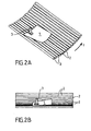
- Figures 2A and 2B show a sheet 1 moving on cylindrical forming rods 2, with the location of an asymmetric blowing nozzle 3 according to the invention.
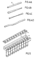
- FIG. 3 represents a bending machine comprising, in known manner, a conveyor forming a shaping bed and constituted by shaping rods 2, which are rotating cylindrical elements arranged in a curved profile path, in practice a circular profile with a concavity turned upwards.
- the conveyor extends in fact without breaking the path followed by the glass sheets heated to the softening temperature in a reheating furnace.
- the conformation bed is tangent to the plane arrival trajectory of the glass sheets on this bed.
- the trajectory followed by the glass sheets is cylindrical, the generatrices of the cylinder being horizontal and perpendicular to the flat feeding direction of the glass.
- the radius of the cylinder on which the trajectory of the glass sheet is based corresponds to the radius of curvature imparted to the sheet of glass. glass in the direction parallel to the scroll direction.
- FIG. 4 A With rotating elements consisting of straight rods, a straight cylinder is obtained (Fig. 4 A). Other forms of revolution are obtained by replacing the straight rods with conical (Fig. 4B), toric (Fig. 4C) or handlebar (Fig. 4D) rods. These other forms involve the use of upper counter rollers.
- FIGS. 2A and 2B air is blown on one side of the sheet (see FIGS. 2A and 2B) by the upper nozzle 3 which delivers air at the temperature chosen between two shaping rods 2.
- the upper nozzle 3 which delivers air at the temperature chosen between two shaping rods 2.
- the Figure 3 also shows a blast nozzle bottom 3a which may be omitted and that could be put into operation in place of the nozzle 3 for the embodiment of Figure 1B or simultaneously thereto for achieving of Figure 1C.
- the nozzles 3 and 3a of asymmetric blowing are arranged upstream of a bending end region wherein is carried out in known way a thermal tempering, to which nozzles 4 of blowing cold air are arranged in four lower and four webs upper bars facing the full width of the bending machine.
- Upper counter-roller type holding means 5 are arranged in the bending-quench zone downstream of the nozzles 3.
- the lower nozzles 4 are directed between two conforming rods 2, and the upper nozzles 4 are directed between two counter-rollers 5.
- the glass sheets are allowed to scroll at a high speed of at least 10 cm / s and preferably of the order of 15 to 18 cm / s, and they then acquire the profile corresponding to the conformation bed under the combined effect.
- the shaping rods are typically 50 to 100 mm apart.
Landscapes
- Chemical & Material Sciences (AREA)
- Engineering & Computer Science (AREA)
- Materials Engineering (AREA)
- Organic Chemistry (AREA)
- Physics & Mathematics (AREA)
- Thermal Sciences (AREA)
- Mechanical Engineering (AREA)
- Re-Forming, After-Treatment, Cutting And Transporting Of Glass Products (AREA)
- Glass Compositions (AREA)
- Joining Of Glass To Other Materials (AREA)
- Shaping Metal By Deep-Drawing, Or The Like (AREA)
Claims (24)
- Verfahren zur Herstellung gebogener Glasscheiben, gemäß welchem zum Biegen die Glasscheiben auf mindestens einem Formgebungsbett mit einer Bahn mit einem in Durchlaufrichtung dieser Scheiben gekrümmten Profil durchlaufen gelassen werden, wobei die Glasscheiben zuvor auf ihre Erweichungstemperatur gebracht worden sind, um ihnen fortschreitend die gewünschte gebogene Form zu verleihen, dadurch gekennzeichnet, dass zwischen der Anfangsphase des Biegevorgangs, in welcher die Glasscheibe beginnt, ihre Form anzunehmen, und der Endphase dieses Biegevorgangs an einer Stelle der Durchlauflinie der Glasscheiben kontinuierlich Luft auf mindestens eine Seite der durchlaufenden Glasscheiben unter Bedingungen geblasen wird, die es ermöglichen, die endgültige Konkavität der gebogenen Glasscheiben in Bezug auf diejenige, die ihnen der letzte Biegevorgang ohne diesen Blasvorgang verliehen hätte, asymmetrisch zu beeinflussen.
- Verfahren nach Anspruch 1, dadurch gekennzeichnet, dass das Aufblasen von Luft auf eine einzige Seite der Glasscheiben in mindestens einem in Bezug auf ihre Durchlaufachse quer verlaufenden Bereich durchgeführt wird.
- Verfahren nach Anspruch 2, dadurch gekennzeichnet, dass der Blasvorgang auf einer einzigen Seite in Bezug auf die Durchlaufachse durchgeführt wird.
- Verfahren nach Anspruch 2, dadurch gekennzeichnet, dass der Blasvorgang in dem gesamten in Bezug auf die Durchlaufachse quer verlaufenden Bereich der Glasscheiben durchgeführt wird.
- Verfahren nach Anspruch 1, dadurch gekennzeichnet, dass das Aufblasen von Luft auf beiden Seiten der Glasscheiben durchgeführt wird, wobei es auf mindestens einer Seite nicht in dem gesamten quer verlaufenden Bereich der Glasscheiben durchgeführt wird.
- Verfahren nach Anspruch 5, dadurch gekennzeichnet, dass das Aufblasen von Luft auf beiden Seiten der durchlaufenden Glasscheiben und in Bezug auf die Durchlaufachse auf einer einzigen Seite durchgeführt wird.
- Verfahren nach einem der Ansprüche 1 bis 6, dadurch gekennzeichnet, dass Luft aufgeblasen wird, die in Bezug auf die Biegetemperatur ausreichend kühl ist, damit der Blasvorgang einen Einfluss auf die fertige Biegung hat.
- Verfahren nach einem der Ansprüche 1 bis 6, dadurch gekennzeichnet, dass Luft aufgeblasen wird, die in Bezug auf die Biegetemperatur ausreichend heiß ist, damit der Blasvorgang einen Einfluss auf die fertige Biegung hat.
- Verfahren nach einem der Ansprüche 1 bis 8, dadurch gekennzeichnet, dass Luft mit einer anderen Temperatur als derjenigen, bei welcher das Biegen durchgeführt wird, aufgeblasen wird, wobei der Blasvorgang eine Vergrößerung der Konkavität auf der Seite der Seite, auf welcher er stattfindet, wenn der Blasvorgang eine Erwärmung verursacht, bewirkt und der Blasvorgang eine Verringerung der Konkavität auf der Seite der Seite, auf welcher er stattfindet, wenn der Blasvorgang eine Abkühlung verursacht, bewirkt.
- Verfahren nach einem der Ansprüche 1 bis 9, dadurch gekennzeichnet, dass Luft mit einer anderen Temperatur als derjenigen, bei welcher der Biegevorgang durchgeführt wird, aufgeblasen wird, um die Konkavität in der zur Durchlaufrichtung quer verlaufenden Ebene weiter zu vergrößern.
- Verfahren nach einem der Ansprüche 1 bis 10, dadurch gekennzeichnet, dass der Blasvorgang durchgeführt wird, indem auf die Glasscheiben Luft mit einem Druck von 4,90·103 bis 9,81·103 Pa (500 bis 1 000 mm Wassersäule) geschickt wird.
- Verfahren nach einem der Ansprüche 1 bis 11, dadurch gekennzeichnet, dass es zu gebogenen Glasscheiben führt, die eine Höhenveränderung von 2/10 mm bis 2 mm gegenüber einem Biegen ohne Blasvorgang aufweisen.
- Verfahren nach einem der Ansprüche 1 bis 12, dadurch gekennzeichnet, dass der Biegevorgang mit einem Krümmungsradius von 1 Meter bis unendlich von einer zur Durchlaufrichtung parallelen Linie und mit einem Krümmungsradius von 5 Metern bis unendlich in einer zur Durchlaufrichtung quer verlaufenden Linie durchgeführt wird.
- Verfahren nach einem der Ansprüche 1 bis 13, dadurch gekennzeichnet, dass Glasscheiben durchlaufen gelassen werden, die ihre Form bei einer Temperatur von 600 bis 700 °C angenommen haben.
- Verfahren nach einem der Ansprüche 1 bis 14, dadurch gekennzeichnet, dass Glasscheiben, um sie auf Erweichungstemperatur zu bringen, in einer ebenen Bahn durch einen Erwärmungsofen und anschließend in einer Bahn mit gekrümmtem Profil, die sich an die vorige ebene Bahn anschließt, auf einem Formgebungsbett, das aus formgebenden Stäben besteht, durchlaufen gelassen werden, wobei der Blasvorgang an einer Stelle durchgeführt wird, die sich in der Bahn mit gekrümmtem Profil befindet, nachdem die Glasscheiben begonnen haben, ihre Form anzunehmen.
- Verfahren nach einem der Ansprüche 1 bis 15, dadurch gekennzeichnet, dass den Glasscheiben ihre Form verliehen wird, indem ein Biegevorgang durch Absinken-Lassen durchgeführt und anschließend der Biegevorgang in einer Bahn mit gekrümmtem Profil auf einem Formgebungsbett, das aus formgebenden Stäben besteht, fortgesetzt wird, wobei der Blasvorgang in dieser Bahn mit gekrümmtem Profil durchgeführt wird.
- Verfahren nach einem der Ansprüche 1 bis 16, dadurch gekennzeichnet, dass nach dem Blasvorgang und vor dem Ende des Biegevorgangs die Glasscheiben vorgespannt werden.
- Verfahren nach Anspruch 17, dadurch gekennzeichnet, dass das Vorspannen durchgeführt wird, indem Luft mit einem Druck von 2,94·104 Pa bis 3,43·104 Pa (3 000 bis 3 500 mm Wassersäule) aufgeblasen wird.
- Gebogene Glasscheiben, die durch das in einem der Ansprüche 1 bis 18 definierte Verfahren erhalten worden sind oder erhalten werden können.
- Gebogene Glasscheiben, die eine Asymmetrie aufweisen, die durch Polariskopie oder durch Spannungsmessungen, für die ein Epibiaskop verwendet wird, nachgewiesen werden kann.
- Glasscheiben nach dem vorhergehenden Anspruch, die mindestens eine gerade Linie aufweisen, die durch Polariskopie oder mit dem Biasographen nachweisbar ist und im Wesentlichen parallel zu einem der Ränder der Glasscheibe und näher zu diesem Rand als zu dem anderen Rand, der zu diesem im Wesentlichen parallel steht, verläuft.
- Vorrichtung zum Biegen von Glasscheiben, die Mittel umfasst, um Glasscheiben (1), die zuvor auf Erweichungstemperatur gebracht worden sind, durchlaufen zu lassen, wobei ihnen die gewünschte gebogene Form verliehen wird, dadurch gekennzeichnet, dass sie außerdem mindestens eine Düse (3, 3a) für das kontinuierliche Aufblasen von Luft umfasst, die an einer Stelle der Durchlauflinie der Glasscheiben, nachdem die Glasscheiben begonnen haben, ihre Form anzunehmen, und vor der letzten Phase des Biegevorgangs angeordnet ist, wobei die Düse/n (3; 3a) angeordnet ist/sind, um auf die Glasscheiben (1) asymmetrisch Luft zu blasen, und geregelt werden, damit durch dieses Aufblasen von Luft die endgültige Konkavität der gebogenen Glasscheiben in Bezug auf diejenige, die ihnen der letzte Biegevorgang ohne diesen Blasvorgang verleihen würde, beeinflusst wird.
- Biegevorrichtung nach dem vorhergehenden Anspruch, dadurch gekennzeichnet, dass sie ein Formgebungsbett umfasst, das von formgebenden Stäben (2) in einer Bahn mit gekrümmtem Profil gebildet wird, wobei die asymmetrische/n Blasdüse/n zwischen zwei benachbarte Formgebungsstäbe (2) des Formgebungsbetts gerichtet ist/sind.
- Biegevorrichtung nach Anspruch 22 oder 23, dadurch gekennzeichnet, dass sie außerdem Blaskästen für das Vorspannen nach der/den asymmetrischen Blasdüse/n umfasst, wobei die Blaskästen für das Vorspannen jeweils Düsen (4) enthalten, die in Leisten angeordnet und zwischen zwei benachbarte Formgebungsstäbe (2) des Formgebungsbetts gerichtet sind.
Applications Claiming Priority (3)
| Application Number | Priority Date | Filing Date | Title |
|---|---|---|---|
| FR0212577A FR2845683B1 (fr) | 2002-10-10 | 2002-10-10 | Procede et machine d'obtention de feuilles de verre bombees |
| FR0212577 | 2002-10-10 | ||
| PCT/FR2003/002959 WO2004033381A1 (fr) | 2002-10-10 | 2003-10-08 | Procede et machine d'obtention de feuilles de verre bombees dissymetriques |
Publications (2)
| Publication Number | Publication Date |
|---|---|
| EP1554224A1 EP1554224A1 (de) | 2005-07-20 |
| EP1554224B1 true EP1554224B1 (de) | 2007-01-03 |
Family
ID=32039593
Family Applications (1)
| Application Number | Title | Priority Date | Filing Date |
|---|---|---|---|
| EP03807881A Expired - Lifetime EP1554224B1 (de) | 2002-10-10 | 2003-10-08 | Verfahren und maschine zur herstellung von asymmetrischen konvexen glasscheiben |
Country Status (14)
| Country | Link |
|---|---|
| US (1) | US20060010916A1 (de) |
| EP (1) | EP1554224B1 (de) |
| JP (1) | JP2006502071A (de) |
| KR (1) | KR20050055071A (de) |
| CN (2) | CN1703377B (de) |
| AT (1) | ATE350351T1 (de) |
| AU (1) | AU2003300159A1 (de) |
| BR (1) | BR0314588A (de) |
| DE (1) | DE60310976T2 (de) |
| ES (1) | ES2279224T3 (de) |
| FR (1) | FR2845683B1 (de) |
| MX (1) | MXPA05003650A (de) |
| PL (1) | PL203891B1 (de) |
| WO (1) | WO2004033381A1 (de) |
Families Citing this family (12)
| Publication number | Priority date | Publication date | Assignee | Title |
|---|---|---|---|---|
| FR2862056B1 (fr) * | 2003-11-12 | 2006-01-13 | Saint Gobain | Procede et machine d'obtention de feuilles de verre bombees |
| CN101492238B (zh) * | 2009-02-27 | 2011-05-18 | 桂林皮尔金顿安全玻璃有限公司 | 玻璃曲面成形系统及使用方法 |
| DE102009025788A1 (de) * | 2009-05-13 | 2010-11-25 | Saint-Gobain Sekurit Deutschland Gmbh & Co. Kg | Verfahren zur Herstellung einer reflexionsverminderten Scheibe |
| FR2945985B1 (fr) | 2009-05-27 | 2011-05-20 | Saint Gobain | Vitrage a faible niveau de double image. |
| US20100318236A1 (en) * | 2009-06-11 | 2010-12-16 | Kilborn John C | Management of the provisioning of energy for a workstation |
| FR2963933B1 (fr) | 2010-08-20 | 2012-08-17 | Saint Gobain | Miroir bombe par pressage |
| CN102408187B (zh) * | 2010-09-20 | 2013-12-25 | 洛阳北方玻璃技术股份有限公司 | 辊道式超大弧长玻璃弯曲钢化方法 |
| FR2966147B1 (fr) | 2010-10-15 | 2016-05-27 | Saint Gobain | Support de trempe thermique |
| US9038421B2 (en) * | 2011-07-01 | 2015-05-26 | Sunpower Corporation | Glass-bending apparatus and method |
| GB201708758D0 (en) * | 2017-06-01 | 2017-07-19 | Pilkington Group Ltd | Method and apparatus for shaping a glass sheet |
| FR3102983B1 (fr) | 2019-11-08 | 2021-11-26 | Saint Gobain | Procédé et dispositif de bombage d’une feuille de verre |
| FR3108060B1 (fr) | 2020-03-12 | 2022-03-04 | Saint Gobain | Vitrage feuillete asymetrique |
Family Cites Families (16)
| Publication number | Priority date | Publication date | Assignee | Title |
|---|---|---|---|---|
| US3396000A (en) * | 1964-08-28 | 1968-08-06 | Libbey Owens Ford Glass Co | Method of and apparatus for bending and tempering glass sheets by differential heating |
| JPS62158128A (ja) * | 1985-12-27 | 1987-07-14 | Central Glass Co Ltd | 薄板ガラスの強化方法 |
| FI76313C (fi) * | 1986-09-22 | 1988-10-10 | Kyro Oy | Foerfarande och anordning foer boejning och tempering av glasskivor. |
| FR2604992B1 (fr) * | 1986-10-01 | 1988-12-02 | Saint Gobain Vitrage | Bombage et trempe de plaques de verre defilant sur un lit de conformation courbe dans la direction de defilement |
| JPS6414121A (en) * | 1987-07-07 | 1989-01-18 | Asahi Glass Co Ltd | Bend forming device for plate glass |
| ES2081450T3 (es) * | 1990-08-17 | 1996-03-16 | Saint Gobain Vitrage | Procedimiento y dispositivo de abombado de hojas de vidrio. |
| FR2691454B1 (fr) * | 1992-05-21 | 1994-07-08 | Saint Gobain Vitrage Int | Procede et dispositif d'obtention de feuilles de verre bombees. |
| US5380348A (en) * | 1993-06-21 | 1995-01-10 | Ford Motor Company | Method for treating glass sheets on a gas hearth |
| US5938810A (en) * | 1996-10-23 | 1999-08-17 | Donnelly Corporation | Apparatus for tempering and bending glass |
| JP3671568B2 (ja) * | 1996-12-26 | 2005-07-13 | 旭硝子株式会社 | 陰極線管用パネルガラスの製造方法 |
| FR2768142B1 (fr) * | 1997-09-11 | 1999-11-05 | Saint Gobain Vitrage | Dispositif de refroidissement de feuilles de verre bombees |
| DE69906369T2 (de) * | 1998-12-03 | 2003-08-21 | Nippon Sheet Glass Co Ltd | Verfahren und vorrichtung zum herstellen einer gebogenen glasplatte |
| JP3717339B2 (ja) * | 1999-07-26 | 2005-11-16 | セントラル硝子株式会社 | ガラス板の曲げ成形装置 |
| JP2001158631A (ja) * | 1999-11-30 | 2001-06-12 | Central Glass Co Ltd | ガラス板の曲げ成形方法 |
| JP4680395B2 (ja) * | 2001-01-24 | 2011-05-11 | 日本板硝子株式会社 | 板ガラスの曲げ成形装置および板ガラスの曲げ成形方法 |
| US20060144090A1 (en) * | 2002-10-21 | 2006-07-06 | Nippon Sheet Blass Co., Ltd. | Method and device for producing curved reinforced glass plate |
-
2002
- 2002-10-10 FR FR0212577A patent/FR2845683B1/fr not_active Expired - Fee Related
-
2003
- 2003-10-08 MX MXPA05003650A patent/MXPA05003650A/es active IP Right Grant
- 2003-10-08 AT AT03807881T patent/ATE350351T1/de not_active IP Right Cessation
- 2003-10-08 CN CN2003801011959A patent/CN1703377B/zh not_active Expired - Fee Related
- 2003-10-08 BR BR0314588-3A patent/BR0314588A/pt not_active Application Discontinuation
- 2003-10-08 DE DE60310976T patent/DE60310976T2/de not_active Expired - Lifetime
- 2003-10-08 AU AU2003300159A patent/AU2003300159A1/en not_active Abandoned
- 2003-10-08 WO PCT/FR2003/002959 patent/WO2004033381A1/fr active IP Right Grant
- 2003-10-08 KR KR1020057006129A patent/KR20050055071A/ko not_active Application Discontinuation
- 2003-10-08 EP EP03807881A patent/EP1554224B1/de not_active Expired - Lifetime
- 2003-10-08 CN CN2011103152017A patent/CN102515484A/zh active Pending
- 2003-10-08 US US10/527,631 patent/US20060010916A1/en not_active Abandoned
- 2003-10-08 PL PL374530A patent/PL203891B1/pl unknown
- 2003-10-08 ES ES03807881T patent/ES2279224T3/es not_active Expired - Lifetime
- 2003-10-08 JP JP2004542565A patent/JP2006502071A/ja active Pending
Also Published As
| Publication number | Publication date |
|---|---|
| PL374530A1 (en) | 2005-10-31 |
| ES2279224T3 (es) | 2007-08-16 |
| DE60310976D1 (de) | 2007-02-15 |
| FR2845683B1 (fr) | 2005-02-25 |
| ATE350351T1 (de) | 2007-01-15 |
| WO2004033381A1 (fr) | 2004-04-22 |
| CN1703377B (zh) | 2012-11-14 |
| JP2006502071A (ja) | 2006-01-19 |
| EP1554224A1 (de) | 2005-07-20 |
| DE60310976T2 (de) | 2007-10-11 |
| AU2003300159A1 (en) | 2004-05-04 |
| CN102515484A (zh) | 2012-06-27 |
| KR20050055071A (ko) | 2005-06-10 |
| BR0314588A (pt) | 2005-08-09 |
| CN1703377A (zh) | 2005-11-30 |
| US20060010916A1 (en) | 2006-01-19 |
| MXPA05003650A (es) | 2005-06-08 |
| PL203891B1 (pl) | 2009-11-30 |
| FR2845683A1 (fr) | 2004-04-16 |
Similar Documents
| Publication | Publication Date | Title |
|---|---|---|
| EP1685073B1 (de) | Verfahren und vorrichtung zur herstellung von konvexen glasplatten | |
| EP1554224B1 (de) | Verfahren und maschine zur herstellung von asymmetrischen konvexen glasscheiben | |
| EP0660809B1 (de) | Verfahren und vorrichtung zum formen von glasscheiben und anwendung dieses verfahren zur herstellung von fenstern mit komplexer form | |
| FR2693184A1 (fr) | Procédé et dispositif de cintrage de feuilles de verre. | |
| EP0474531B1 (de) | Verfahren und Vorrichtung zum Biegen von Glasscheiben | |
| FR2757149A1 (fr) | Dispositif et procede pour bomber des feuilles de verre | |
| EP3947302A1 (de) | Förderung von glasscheiben mittels formrollen | |
| FR2520345A1 (fr) | Procede et dispositif pour la mise en forme de feuilles de verre en mouvement par affaissement sous l'effet de la pesanteur, suivi d'un pressage par rouleaux | |
| EP0415826B1 (de) | Vorrichtung zum Biegen von Glasscheiben in waagerechter Position | |
| EP0571287B1 (de) | Verfahren und Vorrichtung zum Herstellen von gebogenen Glasscheiben | |
| FR2677637A1 (fr) | Procede de preparation de feuilles de verre. | |
| CA2022440C (fr) | Techniques de bombage de feuilles de verre | |
| FR2465692A1 (fr) | Procede et dispositif de faconnage de feuilles de verre a l'aide de moules de formes differentes | |
| WO2020200977A1 (fr) | Convoyage de feuilles de verre par des rouleaux cintrés | |
| WO2021089946A1 (fr) | Procédé et dispositif de bombage d'une feuille de verre | |
| EP0493205B1 (de) | Verfahren und Vorrichtung zum Herstellen von gebogen Glasscheiben | |
| FR2734561A1 (fr) | Moule pour le formage d'un materiau en feuille ramollissable par la chaleur | |
| EP0593363B1 (de) | Verfahren und Vorrichtung zum Biegen von Glasscheiben | |
| WO2022189748A1 (fr) | Procédé et dispositif de positionnement de feuilles de verre pour une installation de fabrication de vitrages | |
| EP1156017B1 (de) | Transfertrad zum Verfahren und Vorrichtung zum Herstellen von Gegenständen aus thermoplastischen Materialen | |
| CA2143650C (fr) | Procede et dispositif de formage de plaques de verre et application de ce procede a l'obtention de vitrages de formes complexes | |
| FR2531699A1 (fr) | Perfectionnements au soufflage de grands objets en verre | |
| FR2811660A1 (fr) | Procede et dispositif de bombage d'une feuille de verre |
Legal Events
| Date | Code | Title | Description |
|---|---|---|---|
| PUAI | Public reference made under article 153(3) epc to a published international application that has entered the european phase |
Free format text: ORIGINAL CODE: 0009012 |
|
| 17P | Request for examination filed |
Effective date: 20050510 |
|
| AK | Designated contracting states |
Kind code of ref document: A1 Designated state(s): AT BE BG CH CY CZ DE DK EE ES FI FR GB GR HU IE IT LI LU MC NL PT RO SE SI SK TR |
|
| AX | Request for extension of the european patent |
Extension state: AL LT LV MK |
|
| GRAP | Despatch of communication of intention to grant a patent |
Free format text: ORIGINAL CODE: EPIDOSNIGR1 |
|
| DAX | Request for extension of the european patent (deleted) | ||
| GRAS | Grant fee paid |
Free format text: ORIGINAL CODE: EPIDOSNIGR3 |
|
| GRAA | (expected) grant |
Free format text: ORIGINAL CODE: 0009210 |
|
| AK | Designated contracting states |
Kind code of ref document: B1 Designated state(s): AT BE BG CH CY CZ DE DK EE ES FI FR GB GR HU IE IT LI LU MC NL PT RO SE SI SK TR |
|
| PG25 | Lapsed in a contracting state [announced via postgrant information from national office to epo] |
Ref country code: DK Free format text: LAPSE BECAUSE OF FAILURE TO SUBMIT A TRANSLATION OF THE DESCRIPTION OR TO PAY THE FEE WITHIN THE PRESCRIBED TIME-LIMIT Effective date: 20070103 Ref country code: NL Free format text: LAPSE BECAUSE OF FAILURE TO SUBMIT A TRANSLATION OF THE DESCRIPTION OR TO PAY THE FEE WITHIN THE PRESCRIBED TIME-LIMIT Effective date: 20070103 Ref country code: SI Free format text: LAPSE BECAUSE OF FAILURE TO SUBMIT A TRANSLATION OF THE DESCRIPTION OR TO PAY THE FEE WITHIN THE PRESCRIBED TIME-LIMIT Effective date: 20070103 Ref country code: IE Free format text: LAPSE BECAUSE OF FAILURE TO SUBMIT A TRANSLATION OF THE DESCRIPTION OR TO PAY THE FEE WITHIN THE PRESCRIBED TIME-LIMIT Effective date: 20070103 Ref country code: FI Free format text: LAPSE BECAUSE OF FAILURE TO SUBMIT A TRANSLATION OF THE DESCRIPTION OR TO PAY THE FEE WITHIN THE PRESCRIBED TIME-LIMIT Effective date: 20070103 Ref country code: AT Free format text: LAPSE BECAUSE OF FAILURE TO SUBMIT A TRANSLATION OF THE DESCRIPTION OR TO PAY THE FEE WITHIN THE PRESCRIBED TIME-LIMIT Effective date: 20070103 |
|
| REG | Reference to a national code |
Ref country code: GB Ref legal event code: FG4D Free format text: NOT ENGLISH |
|
| REF | Corresponds to: |
Ref document number: 60310976 Country of ref document: DE Date of ref document: 20070215 Kind code of ref document: P |
|
| REG | Reference to a national code |
Ref country code: IE Ref legal event code: FG4D Free format text: LANGUAGE OF EP DOCUMENT: FRENCH |
|
| REG | Reference to a national code |
Ref country code: CH Ref legal event code: NV Representative=s name: KIRKER & CIE SA |
|
| PG25 | Lapsed in a contracting state [announced via postgrant information from national office to epo] |
Ref country code: BG Free format text: LAPSE BECAUSE OF EXPIRATION OF PROTECTION Effective date: 20070404 |
|
| REG | Reference to a national code |
Ref country code: SE Ref legal event code: TRGR |
|
| GBT | Gb: translation of ep patent filed (gb section 77(6)(a)/1977) |
Effective date: 20070319 |
|
| PG25 | Lapsed in a contracting state [announced via postgrant information from national office to epo] |
Ref country code: PT Free format text: LAPSE BECAUSE OF FAILURE TO SUBMIT A TRANSLATION OF THE DESCRIPTION OR TO PAY THE FEE WITHIN THE PRESCRIBED TIME-LIMIT Effective date: 20070604 |
|
| NLV1 | Nl: lapsed or annulled due to failure to fulfill the requirements of art. 29p and 29m of the patents act | ||
| REG | Reference to a national code |
Ref country code: ES Ref legal event code: FG2A Ref document number: 2279224 Country of ref document: ES Kind code of ref document: T3 |
|
| REG | Reference to a national code |
Ref country code: IE Ref legal event code: FD4D |
|
| PLBE | No opposition filed within time limit |
Free format text: ORIGINAL CODE: 0009261 |
|
| STAA | Information on the status of an ep patent application or granted ep patent |
Free format text: STATUS: NO OPPOSITION FILED WITHIN TIME LIMIT |
|
| PG25 | Lapsed in a contracting state [announced via postgrant information from national office to epo] |
Ref country code: SK Free format text: LAPSE BECAUSE OF FAILURE TO SUBMIT A TRANSLATION OF THE DESCRIPTION OR TO PAY THE FEE WITHIN THE PRESCRIBED TIME-LIMIT Effective date: 20070103 |
|
| 26N | No opposition filed |
Effective date: 20071005 |
|
| PG25 | Lapsed in a contracting state [announced via postgrant information from national office to epo] |
Ref country code: RO Free format text: LAPSE BECAUSE OF FAILURE TO SUBMIT A TRANSLATION OF THE DESCRIPTION OR TO PAY THE FEE WITHIN THE PRESCRIBED TIME-LIMIT Effective date: 20070103 Ref country code: CZ Free format text: LAPSE BECAUSE OF FAILURE TO SUBMIT A TRANSLATION OF THE DESCRIPTION OR TO PAY THE FEE WITHIN THE PRESCRIBED TIME-LIMIT Effective date: 20070103 |
|
| PG25 | Lapsed in a contracting state [announced via postgrant information from national office to epo] |
Ref country code: GR Free format text: LAPSE BECAUSE OF FAILURE TO SUBMIT A TRANSLATION OF THE DESCRIPTION OR TO PAY THE FEE WITHIN THE PRESCRIBED TIME-LIMIT Effective date: 20070404 |
|
| PG25 | Lapsed in a contracting state [announced via postgrant information from national office to epo] |
Ref country code: MC Free format text: LAPSE BECAUSE OF NON-PAYMENT OF DUE FEES Effective date: 20071031 |
|
| PG25 | Lapsed in a contracting state [announced via postgrant information from national office to epo] |
Ref country code: EE Free format text: LAPSE BECAUSE OF FAILURE TO SUBMIT A TRANSLATION OF THE DESCRIPTION OR TO PAY THE FEE WITHIN THE PRESCRIBED TIME-LIMIT Effective date: 20070103 |
|
| PGFP | Annual fee paid to national office [announced via postgrant information from national office to epo] |
Ref country code: CH Payment date: 20081016 Year of fee payment: 6 |
|
| PG25 | Lapsed in a contracting state [announced via postgrant information from national office to epo] |
Ref country code: CY Free format text: LAPSE BECAUSE OF FAILURE TO SUBMIT A TRANSLATION OF THE DESCRIPTION OR TO PAY THE FEE WITHIN THE PRESCRIBED TIME-LIMIT Effective date: 20070103 |
|
| PG25 | Lapsed in a contracting state [announced via postgrant information from national office to epo] |
Ref country code: HU Free format text: LAPSE BECAUSE OF FAILURE TO SUBMIT A TRANSLATION OF THE DESCRIPTION OR TO PAY THE FEE WITHIN THE PRESCRIBED TIME-LIMIT Effective date: 20070704 |
|
| REG | Reference to a national code |
Ref country code: CH Ref legal event code: PL |
|
| PG25 | Lapsed in a contracting state [announced via postgrant information from national office to epo] |
Ref country code: LI Free format text: LAPSE BECAUSE OF NON-PAYMENT OF DUE FEES Effective date: 20091031 Ref country code: CH Free format text: LAPSE BECAUSE OF NON-PAYMENT OF DUE FEES Effective date: 20091031 |
|
| PG25 | Lapsed in a contracting state [announced via postgrant information from national office to epo] |
Ref country code: LU Free format text: LAPSE BECAUSE OF NON-PAYMENT OF DUE FEES Effective date: 20141008 |
|
| REG | Reference to a national code |
Ref country code: FR Ref legal event code: PLFP Year of fee payment: 13 |
|
| REG | Reference to a national code |
Ref country code: FR Ref legal event code: PLFP Year of fee payment: 14 |
|
| REG | Reference to a national code |
Ref country code: FR Ref legal event code: PLFP Year of fee payment: 15 |
|
| REG | Reference to a national code |
Ref country code: FR Ref legal event code: PLFP Year of fee payment: 16 |
|
| PG25 | Lapsed in a contracting state [announced via postgrant information from national office to epo] |
Ref country code: LU Free format text: LAPSE BECAUSE OF NON-PAYMENT OF DUE FEES Effective date: 20141008 |
|
| PGRI | Patent reinstated in contracting state [announced from national office to epo] |
Ref country code: LU Effective date: 20150817 |
|
| PGFP | Annual fee paid to national office [announced via postgrant information from national office to epo] |
Ref country code: IT Payment date: 20210910 Year of fee payment: 19 Ref country code: LU Payment date: 20210924 Year of fee payment: 19 |
|
| PGFP | Annual fee paid to national office [announced via postgrant information from national office to epo] |
Ref country code: SE Payment date: 20210929 Year of fee payment: 19 Ref country code: BE Payment date: 20210916 Year of fee payment: 19 Ref country code: GB Payment date: 20210831 Year of fee payment: 19 |
|
| PGFP | Annual fee paid to national office [announced via postgrant information from national office to epo] |
Ref country code: ES Payment date: 20211110 Year of fee payment: 19 Ref country code: TR Payment date: 20211006 Year of fee payment: 19 Ref country code: DE Payment date: 20210831 Year of fee payment: 19 |
|
| PGFP | Annual fee paid to national office [announced via postgrant information from national office to epo] |
Ref country code: FR Payment date: 20211028 Year of fee payment: 19 |
|
| REG | Reference to a national code |
Ref country code: DE Ref legal event code: R119 Ref document number: 60310976 Country of ref document: DE |
|
| REG | Reference to a national code |
Ref country code: SE Ref legal event code: EUG |
|
| REG | Reference to a national code |
Ref country code: BE Ref legal event code: MM Effective date: 20221031 |
|
| GBPC | Gb: european patent ceased through non-payment of renewal fee |
Effective date: 20221008 |
|
| PG25 | Lapsed in a contracting state [announced via postgrant information from national office to epo] |
Ref country code: LU Free format text: LAPSE BECAUSE OF NON-PAYMENT OF DUE FEES Effective date: 20221008 |
|
| PG25 | Lapsed in a contracting state [announced via postgrant information from national office to epo] |
Ref country code: FR Free format text: LAPSE BECAUSE OF NON-PAYMENT OF DUE FEES Effective date: 20221031 Ref country code: DE Free format text: LAPSE BECAUSE OF NON-PAYMENT OF DUE FEES Effective date: 20230503 |
|
| PG25 | Lapsed in a contracting state [announced via postgrant information from national office to epo] |
Ref country code: SE Free format text: LAPSE BECAUSE OF NON-PAYMENT OF DUE FEES Effective date: 20221009 |
|
| PG25 | Lapsed in a contracting state [announced via postgrant information from national office to epo] |
Ref country code: BE Free format text: LAPSE BECAUSE OF NON-PAYMENT OF DUE FEES Effective date: 20221031 |
|
| PG25 | Lapsed in a contracting state [announced via postgrant information from national office to epo] |
Ref country code: IT Free format text: LAPSE BECAUSE OF NON-PAYMENT OF DUE FEES Effective date: 20221008 Ref country code: GB Free format text: LAPSE BECAUSE OF NON-PAYMENT OF DUE FEES Effective date: 20221008 |
|
| REG | Reference to a national code |
Ref country code: ES Ref legal event code: FD2A Effective date: 20231128 |
|
| PG25 | Lapsed in a contracting state [announced via postgrant information from national office to epo] |
Ref country code: ES Free format text: LAPSE BECAUSE OF NON-PAYMENT OF DUE FEES Effective date: 20221009 |
|
| PG25 | Lapsed in a contracting state [announced via postgrant information from national office to epo] |
Ref country code: ES Free format text: LAPSE BECAUSE OF NON-PAYMENT OF DUE FEES Effective date: 20221009 |