EP1554224B1 - Method and machine for obtaining asymmetric convex glass sheets - Google Patents
Method and machine for obtaining asymmetric convex glass sheets Download PDFInfo
- Publication number
- EP1554224B1 EP1554224B1 EP03807881A EP03807881A EP1554224B1 EP 1554224 B1 EP1554224 B1 EP 1554224B1 EP 03807881 A EP03807881 A EP 03807881A EP 03807881 A EP03807881 A EP 03807881A EP 1554224 B1 EP1554224 B1 EP 1554224B1
- Authority
- EP
- European Patent Office
- Prior art keywords
- blowing
- bending
- glass sheets
- sheets
- air
- Prior art date
- Legal status (The legal status is an assumption and is not a legal conclusion. Google has not performed a legal analysis and makes no representation as to the accuracy of the status listed.)
- Expired - Lifetime
Links
- 239000011521 glass Substances 0.000 title claims abstract description 80
- 238000000034 method Methods 0.000 title claims abstract description 34
- 238000007664 blowing Methods 0.000 claims abstract description 78
- 238000005452 bending Methods 0.000 claims abstract description 63
- 238000004519 manufacturing process Methods 0.000 claims abstract description 7
- 238000007493 shaping process Methods 0.000 claims description 33
- XLYOFNOQVPJJNP-UHFFFAOYSA-N water Substances O XLYOFNOQVPJJNP-UHFFFAOYSA-N 0.000 claims description 4
- 238000001816 cooling Methods 0.000 claims description 2
- 238000010438 heat treatment Methods 0.000 claims description 2
- 230000001747 exhibiting effect Effects 0.000 claims 3
- 238000003491 array Methods 0.000 claims 1
- 238000006073 displacement reaction Methods 0.000 abstract 1
- 238000010791 quenching Methods 0.000 description 6
- 241001639412 Verres Species 0.000 description 3
- 238000000465 moulding Methods 0.000 description 3
- 229920000297 Rayon Polymers 0.000 description 2
- 230000000694 effects Effects 0.000 description 2
- 238000003825 pressing Methods 0.000 description 2
- 230000000171 quenching effect Effects 0.000 description 2
- 239000002964 rayon Substances 0.000 description 2
- 238000003303 reheating Methods 0.000 description 2
- 238000005496 tempering Methods 0.000 description 2
- 238000011144 upstream manufacturing Methods 0.000 description 2
- 241001415961 Gaviidae Species 0.000 description 1
- 230000002301 combined effect Effects 0.000 description 1
- 238000010586 diagram Methods 0.000 description 1
- 238000009826 distribution Methods 0.000 description 1
- 239000012530 fluid Substances 0.000 description 1
- 230000005484 gravity Effects 0.000 description 1
- 238000005259 measurement Methods 0.000 description 1
- 238000012986 modification Methods 0.000 description 1
- 230000004048 modification Effects 0.000 description 1
- 230000003287 optical effect Effects 0.000 description 1
- 239000007787 solid Substances 0.000 description 1
- 239000005341 toughened glass Substances 0.000 description 1
- 238000004804 winding Methods 0.000 description 1
Images


Classifications
-
- C—CHEMISTRY; METALLURGY
- C03—GLASS; MINERAL OR SLAG WOOL
- C03B—MANUFACTURE, SHAPING, OR SUPPLEMENTARY PROCESSES
- C03B23/00—Re-forming shaped glass
- C03B23/02—Re-forming glass sheets
- C03B23/023—Re-forming glass sheets by bending
- C03B23/035—Re-forming glass sheets by bending using a gas cushion or by changing gas pressure, e.g. by applying vacuum or blowing for supporting the glass while bending
- C03B23/0352—Re-forming glass sheets by bending using a gas cushion or by changing gas pressure, e.g. by applying vacuum or blowing for supporting the glass while bending by suction or blowing out for providing the deformation force to bend the glass sheet
- C03B23/0355—Re-forming glass sheets by bending using a gas cushion or by changing gas pressure, e.g. by applying vacuum or blowing for supporting the glass while bending by suction or blowing out for providing the deformation force to bend the glass sheet by blowing without suction directly on the glass sheet
-
- C—CHEMISTRY; METALLURGY
- C03—GLASS; MINERAL OR SLAG WOOL
- C03B—MANUFACTURE, SHAPING, OR SUPPLEMENTARY PROCESSES
- C03B23/00—Re-forming shaped glass
- C03B23/02—Re-forming glass sheets
- C03B23/023—Re-forming glass sheets by bending
- C03B23/025—Re-forming glass sheets by bending by gravity
-
- C—CHEMISTRY; METALLURGY
- C03—GLASS; MINERAL OR SLAG WOOL
- C03B—MANUFACTURE, SHAPING, OR SUPPLEMENTARY PROCESSES
- C03B23/00—Re-forming shaped glass
- C03B23/02—Re-forming glass sheets
- C03B23/023—Re-forming glass sheets by bending
- C03B23/025—Re-forming glass sheets by bending by gravity
- C03B23/0252—Re-forming glass sheets by bending by gravity by gravity only, e.g. sagging
- C03B23/0254—Re-forming glass sheets by bending by gravity by gravity only, e.g. sagging in a continuous way, e.g. gravity roll bending
-
- C—CHEMISTRY; METALLURGY
- C03—GLASS; MINERAL OR SLAG WOOL
- C03B—MANUFACTURE, SHAPING, OR SUPPLEMENTARY PROCESSES
- C03B23/00—Re-forming shaped glass
- C03B23/02—Re-forming glass sheets
- C03B23/023—Re-forming glass sheets by bending
- C03B23/025—Re-forming glass sheets by bending by gravity
- C03B23/0256—Gravity bending accelerated by applying mechanical forces, e.g. inertia, weights or local forces
-
- C—CHEMISTRY; METALLURGY
- C03—GLASS; MINERAL OR SLAG WOOL
- C03B—MANUFACTURE, SHAPING, OR SUPPLEMENTARY PROCESSES
- C03B27/00—Tempering or quenching glass products
- C03B27/04—Tempering or quenching glass products using gas
- C03B27/0404—Nozzles, blow heads, blowing units or their arrangements, specially adapted for flat or bent glass sheets
- C03B27/0408—Nozzles, blow heads, blowing units or their arrangements, specially adapted for flat or bent glass sheets being dismountable
-
- C—CHEMISTRY; METALLURGY
- C03—GLASS; MINERAL OR SLAG WOOL
- C03B—MANUFACTURE, SHAPING, OR SUPPLEMENTARY PROCESSES
- C03B27/00—Tempering or quenching glass products
- C03B27/04—Tempering or quenching glass products using gas
- C03B27/044—Tempering or quenching glass products using gas for flat or bent glass sheets being in a horizontal position
- C03B27/0442—Tempering or quenching glass products using gas for flat or bent glass sheets being in a horizontal position for bent glass sheets
- C03B27/0447—Tempering or quenching glass products using gas for flat or bent glass sheets being in a horizontal position for bent glass sheets the quench unit being variably adaptable to the bend of the sheet
-
- C—CHEMISTRY; METALLURGY
- C03—GLASS; MINERAL OR SLAG WOOL
- C03B—MANUFACTURE, SHAPING, OR SUPPLEMENTARY PROCESSES
- C03B35/00—Transporting of glass products during their manufacture, e.g. hot glass lenses, prisms
- C03B35/14—Transporting hot glass sheets or ribbons, e.g. by heat-resistant conveyor belts or bands
- C03B35/16—Transporting hot glass sheets or ribbons, e.g. by heat-resistant conveyor belts or bands by roller conveyors
- C03B35/166—Transporting hot glass sheets or ribbons, e.g. by heat-resistant conveyor belts or bands by roller conveyors specially adapted for both flat and bent sheets or ribbons
Definitions
- the present invention relates to the techniques for obtaining curved and possibly thermally tempered glass sheets, whether the sheets are curved in cylindrical shapes or non-cylindrical complex shapes.
- the invention relates to those techniques in which the glass sheets are allowed to scroll on at least one shaping bed formed by shaping rods, for example rotating elements arranged in a curved profile path in the direction of the scrolling glass sheets.
- the invention applies for example to the production of automotive glazings, for example of the side window type.
- Such bending techniques are currently implemented with very high production rates due in particular to the possibility of following glass sheets spaced from each other by a few centimeters. They allow a very great reproducibility of the curve and the optical quality of the final glazing.
- the present invention proposes an improvement to the processes and current bending machines, said improvement consisting of a continuous air blowing asymmetrically on the glass sheets under conditions capable of influencing the final concavity of the sheet relative to a conventional bending without this asymmetrical blowing.
- EP-A-0 471 620 discloses a bending process whereby glass sheets scroll until they are placed in a solid bending form. The sheets are then lifted by a hot updraft, with additional blowing of hot gas at fold lines, to increase the viscosity of the glass edge to better press against the bending shape, the pressing by the annular frame which follows this molding being no more than a finishing press. The additional gas blowing is not intended to influence the concavity compared to what the final bending would have done without blowing. This document does not teach blowing during the scrolling of the sheets.
- EP-A-0 298 426 discloses bending by applying a heated glass sheet against the curved surface of a mold, the sheet being lifted by air blown by nozzles and aspirated by a system. The sheet thus receives its general shape and the bending is finished on the sides where the curvature is stronger by another blow by the system.
- EP-A-0 838 438 discloses a bending obtained by winding a heated glass sheet onto a rigid molding surface, the pressing member of the glass sheet against this surface being a flexible diaphragm pressurized with fluid.
- Patent Abstracts of Japan Vol 2000, No. 19, June 5, 2001 JP 2001 039724 A
- Patent Abstracts of Japan Vol 2000, No. 23, February 10, 2001 JP 2001 158631 A
- the present invention therefore firstly relates to a method of manufacturing curved glass sheets according to which glass sheets are scrolled on at least one conformation bed for bending in a curved profile path in the direction of travel of said sheets, said glass sheets having been previously brought to their softening temperature by progressively giving them the desired convex shape, characterized in that between the initial phase of the bending in which the sheet begins to take shape and the final phase said bending is effected, at a location of the scroll line of sheets, a continuous air blowing on at least one side of the scrolling glass sheets, under conditions capable of asymmetrically influencing the final concavity of the curved glass sheets compared to what would have given the final bending without said blowing.
- the air blowing on one side of the glass sheets is conducted on at least a transverse region thereof relative to the axis of travel. It is thus possible to blow only one side with respect to the scroll axis, or to blow the entire transverse region of the glass sheets relative to the axis of travel.
- the air blowing is conducted on both sides of the glass sheets, said blowing not being conducted over the entire transverse region of the glass sheets on at least one of the faces. It is thus possible to drive the air blowing on either side of the scrolling glass sheets and on one side only with respect to the scroll axis.
- air can be blown sufficiently cold or hot enough with respect to the bending temperature so that the blowing has an influence on the final bending.
- Air can be blown at a temperature different from the temperature at which the bending is done to give more concavity on one side of the glass sheet. If the blowing tends to lower the temperature of the face of the glass sheet receiving said blowing, the concavity will be increased on the other side of the sheet, that is to say on the side that has not received said blowing , in comparison with the concavity obtained in the absence of said blowing. If the blowing tends to increase the temperature of the face of the glass sheet receiving said blowing, the concavity will be locally increased on the side having received said blowing, compared with the concavity obtained in the absence of said blowing.
- air is blown at a temperature different from the temperature at which the bending is performed, the blowing producing an increase in concavity on the side of the face receiving it if the blowing produces a heating, the blowing producing a Concavity decrease on the side of the receiving face if the blowing produces cooling.
- both sides of the sheet have substantially the same temperature, in general, the concavity is increased by blowing the side of the face of the hottest glass.
- the concavity is increased in all directions on the side of the glass face having its concavity increased, that is to say, both in the direction of travel and in the plane perpendicular to the direction of travel. This effect is observable at the places that have been blown. Only a part of the sheet can therefore be affected by this effect (in the case of FIGS. 1A, 1B, 1C).
- said blowing is effected by directing air onto the glass sheets at a pressure of 4.90 x 10 3 at 9.81 x 10 3 Pa (500 to 1000 mm of water column).
- the method according to the invention leads in particular to curved glass sheets having dimensional variations of 2/10 mm to 2 mm with respect to a bending without blowing.
- sheets of glass are scrolled along a flat trajectory in a reheating furnace to bring them to a softening temperature, and then following a curved profile trajectory, tangent to the aforementioned flat trajectory on a bed of conformation constituted by shaping rods, the blowing being conducted at a location along the curved profile path after the sheets have begun to take shape.
- the present invention also relates to curved glass sheets obtained or obtainable by the process as defined above; and on curved glass sheets having an asymmetry that can be detected by polariscopy or by stress measurements using techniques using an epibiascope (possibly also a stratoréfracto doctors or a biasograph). Indeed, the blowing exerted continuously and asymmetrically on the scrolling sheets can produce traces parallel to the direction of travel, more particularly in the cases illustrated by Figures 1a, 1b, 1c.
- the invention particularly relates to a curved glass sheet having at least one detectable straight line in polariscopy or biasograph, substantially parallel to one of the edges of the sheet and closer to this edge than the other edge which it is substantially parallel (because of the dissymmetry with respect to the scroll axis in the case of Figures 1a, 1b, 1c).
- the present invention finally relates to a machine for bending glass sheets comprising means for scrolling glass sheets which have been previously brought to their softening temperature by giving them the desired convex shape, characterized in that it further comprises at least one continuous air blast nozzle disposed at a location of the scroll line of the sheets after the sheets have begun to take shape and before the final phase of said bending, the nozzle or nozzles being arranged to achieve an asymmetrical air blow on said sheets, and set so that said air blowing influences the final concavity of the curved glass sheets relative to what would have given the final bending without said blowing.
- the bending machine according to the invention advantageously comprises a shaping bed consisting of shaping rods in a curved profile path, the asymmetrical blowing nozzle or nozzles being directed between two shaping rods close to the shaping bed.
- It may also further comprise quenching blow boxes downstream of the asymmetric blowing nozzle (s), said quench blowing casings each comprising nozzles arranged in strips and directed between two shaping rods close to the shaping bed.
- a sheet of cut glass 1 is schematically represented in view of the production of an automobile side window, and the arrow f indicates its axis of movement on the line of the automobile. bending.
- an asymmetrical blowing of hot or cold air is carried out on the sheet 1 in movement before the final bending, for example by the top of the sheet 1 and on one side (FIG. 1A), from below the sheet 1 and from one side (Figure 1B), both from above and below the sheet 1 and from the same side (Figure 1C), from the underside of the sheet 1 and over the entire transverse region thereof (Figure 1D), or by the top of the sheet 1 and over the entire transverse region thereof ( Figure 1E).
- the concavity is modified as previously explained, not only with regard to the concavity in the direction of the scroll, but also with regard to relates to the concavity in the plane perpendicular to the direction of scrolling.
- the asymmetrical blowing will make it possible to modify the bending of one side of the window, such a method advantageously applying to the manufacture of a front side window of a car which is more curved at the back only at the front.
- the asymmetrical blowing according to the invention then appears as an additional means of adjusting the desired final shape for the curved sheet.
- the bending is influenced over the entire transverse region of the scrolling sheet, which is particularly useful when making series of curved sheets of different shapes.
- the asymmetric blowing is a simple means of adjustment, avoiding rebuilding the bending line.
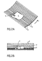
- Figures 2A and 2B show a sheet 1 moving on cylindrical forming rods 2, with the location of an asymmetric blowing nozzle 3 according to the invention.
- FIG. 3 represents a bending machine comprising, in known manner, a conveyor forming a shaping bed and constituted by shaping rods 2, which are rotating cylindrical elements arranged in a curved profile path, in practice a circular profile with a concavity turned upwards.
- the conveyor extends in fact without breaking the path followed by the glass sheets heated to the softening temperature in a reheating furnace.
- the conformation bed is tangent to the plane arrival trajectory of the glass sheets on this bed.
- the trajectory followed by the glass sheets is cylindrical, the generatrices of the cylinder being horizontal and perpendicular to the flat feeding direction of the glass.
- the radius of the cylinder on which the trajectory of the glass sheet is based corresponds to the radius of curvature imparted to the sheet of glass. glass in the direction parallel to the scroll direction.
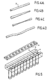
- FIG. 4 A With rotating elements consisting of straight rods, a straight cylinder is obtained (Fig. 4 A). Other forms of revolution are obtained by replacing the straight rods with conical (Fig. 4B), toric (Fig. 4C) or handlebar (Fig. 4D) rods. These other forms involve the use of upper counter rollers.
- FIGS. 2A and 2B air is blown on one side of the sheet (see FIGS. 2A and 2B) by the upper nozzle 3 which delivers air at the temperature chosen between two shaping rods 2.
- the upper nozzle 3 which delivers air at the temperature chosen between two shaping rods 2.
- the Figure 3 also shows a blast nozzle bottom 3a which may be omitted and that could be put into operation in place of the nozzle 3 for the embodiment of Figure 1B or simultaneously thereto for achieving of Figure 1C.
- the nozzles 3 and 3a of asymmetric blowing are arranged upstream of a bending end region wherein is carried out in known way a thermal tempering, to which nozzles 4 of blowing cold air are arranged in four lower and four webs upper bars facing the full width of the bending machine.
- Upper counter-roller type holding means 5 are arranged in the bending-quench zone downstream of the nozzles 3.
- the lower nozzles 4 are directed between two conforming rods 2, and the upper nozzles 4 are directed between two counter-rollers 5.
- the glass sheets are allowed to scroll at a high speed of at least 10 cm / s and preferably of the order of 15 to 18 cm / s, and they then acquire the profile corresponding to the conformation bed under the combined effect.
- the shaping rods are typically 50 to 100 mm apart.
Abstract
Description
La présente invention concerne les techniques d'obtention de feuilles de verre bombées et éventuellement trempées thermiquement, que les feuilles soient bombées selon des formes cylindriques ou des formes complexes non cylindriques.The present invention relates to the techniques for obtaining curved and possibly thermally tempered glass sheets, whether the sheets are curved in cylindrical shapes or non-cylindrical complex shapes.
Plus particulièrement, l'invention concerne celles de ces techniques dans lesquelles les feuilles de verre sont amenées à défiler sur au moins un lit de conformation constitué par des tiges conformatrices, par exemple des éléments tournants disposés selon un trajet à profil courbe dans la direction du défilement des feuilles de verre.More particularly, the invention relates to those techniques in which the glass sheets are allowed to scroll on at least one shaping bed formed by shaping rods, for example rotating elements arranged in a curved profile path in the direction of the scrolling glass sheets.
L'invention s'applique par exemple à la réalisation de vitrages automobiles, par exemple du type vitres latérales.The invention applies for example to the production of automotive glazings, for example of the side window type.
De telles techniques de bombage sont actuellement mises en oeuvre avec des cadences de production très grandes dues notamment à la possibilité de faire suivre des feuilles de verre espacées les unes des autres de quelques centimètres seulement. Elles permettent une très grande reproductibilité du galbe et de la qualité optique des vitrages finals.Such bending techniques are currently implemented with very high production rates due in particular to the possibility of following glass sheets spaced from each other by a few centimeters. They allow a very great reproducibility of the curve and the optical quality of the final glazing.
Toutefois, les formes de ces feuilles bombées deviennent de plus en plus complexes.However, the shapes of these curved leaves become more and more complex.
Certes il est possible de jouer sur la forme des tiges conformatrices utilisées pour constituer le lit de conformation pour le bombage. Toutefois, cela nécessite de construire, à chaque nouvelle série de feuilles de verre bombées, un nouveau lit de conformation avec un montage long et précis des nouvelles tiges conformatrices, alors même que les modifications à apporter à un galbage sont de l'ordre de quelques 1/10 de millimètre à quelques millimètres.Certainly it is possible to play on the shape of the shaping rods used to form the conformation bed for bending. However, this requires building, with each new series of curved glass sheets, a new conformation bed with a long and precise assembly of the new shaping rods, even though the modifications to be made to a shaping are of the order of a few 1/10 of a millimeter to a few millimeters.
Pour résoudre cette difficulté, la présente invention propose un perfectionnement aux procédés et machines de bombage actuels, ledit perfectionnement consistant en un soufflage continu d'air de façon dissymétrique sur les feuilles de verre dans des conditions aptes à influencer la concavité finale de la feuille par rapport à un bombage traditionnel sans ce soufflage dissymétrique.To solve this problem, the present invention proposes an improvement to the processes and current bending machines, said improvement consisting of a continuous air blowing asymmetrically on the glass sheets under conditions capable of influencing the final concavity of the sheet relative to a conventional bending without this asymmetrical blowing.
Le EP-A-0 471 620 décrit un procédé de bombage selon lequel des feuilles de verre défilent jusqu'à se trouver placées sous une forme pleine de bombage. Les feuilles sont ensuite soulevées par un courant ascendant chaud, avec soufflage supplémentaire de gaz chaud au niveau de lignes de pliure, pour augmenter la viscosité du verre en bordure afin de mieux le plaquer contre la forme de bombage, le pressage par le cadre annulaire qui fait suite à ce moulage n'étant plus qu'un pressage de finition. Le soufflage supplémentaire de gaz ne vise pas à influencer la concavité par rapport à ce qu'aurait donné le bombage final sans le soufflage. Ce document n'enseigne pas de soufflage pendant le défilement des feuilles.EP-A-0 471 620 discloses a bending process whereby glass sheets scroll until they are placed in a solid bending form. The sheets are then lifted by a hot updraft, with additional blowing of hot gas at fold lines, to increase the viscosity of the glass edge to better press against the bending shape, the pressing by the annular frame which follows this molding being no more than a finishing press. The additional gas blowing is not intended to influence the concavity compared to what the final bending would have done without blowing. This document does not teach blowing during the scrolling of the sheets.
Le EP-A-0 298 426 décrit un bombage par application d'une feuille de verre chauffée contre la surface cintrée d'un moule, la feuille étant soulevée par de l'air soufflé par des buses et aspirée par un système. La feuille reçoit ainsi sa forme générale et le bombage est terminé sur les côtés où la courbure est plus forte par un autre soufflage par le système.EP-A-0 298 426 discloses bending by applying a heated glass sheet against the curved surface of a mold, the sheet being lifted by air blown by nozzles and aspirated by a system. The sheet thus receives its general shape and the bending is finished on the sides where the curvature is stronger by another blow by the system.
Le EP-A-0 838 438 décrit un bombage obtenu par enroulement d'une feuille de verre chauffée sur une surface de moulage rigide, l'élément de pressage de la feuille de verre contre cette surface étant un diaphragme flexible pressurisé par du fluide.EP-A-0 838 438 discloses a bending obtained by winding a heated glass sheet onto a rigid molding surface, the pressing member of the glass sheet against this surface being a flexible diaphragm pressurized with fluid.
Patent Abstracts of Japan vol 2000, n°19, 5 juin 2001 (JP 2001 039724 A) et Patent Abstracts of Japan vol 2000, n°23, 10 février 2001 (JP 2001 158631 A) décrivent le moulage d'une plaque de verre sur la surface inférieure d'un moule, les buses soufflant de l'air pour soulever la feuille de verre étant disposées et orientées pour rendre uniforme la distribution des jets d'air sur le verre.Patent Abstracts of Japan Vol 2000, No. 19, June 5, 2001 (JP 2001 039724 A) and Patent Abstracts of Japan Vol 2000, No. 23, February 10, 2001 (JP 2001 158631 A) describe the molding of a glass plate on the bottom surface of a mold, the nozzles blowing air to lift the glass sheet being arranged and oriented to make uniform the distribution of air jets on the glass.
La présente invention a donc d'abord pour objet un procédé de fabrication de feuilles de verre bombées suivant lequel on fait défiler des feuilles de verre sur au moins un lit de conformation pour le bombage selon un trajet à profil courbe dans la direction du défilement desdites feuilles, lesdites feuilles de verre ayant été au préalable amenées à leur température de ramollissement en leur conférant progressivement la forme bombée souhaitée, caractérisé par le fait qu'entre la phase initiale du bombage dans laquelle la feuille commence à prendre sa forme et la phase finale dudit bombage, on effectue, en un emplacement de la ligne de défilement des feuilles, un soufflage d'air en continu sur au moins une face des feuilles de verre en défilement, dans des conditions capables d'influencer de façon dissymétrique la concavité finale des feuilles de verre bombées par rapport à ce qu'aurait donné le bombage final sans ledit soufflage.The present invention therefore firstly relates to a method of manufacturing curved glass sheets according to which glass sheets are scrolled on at least one conformation bed for bending in a curved profile path in the direction of travel of said sheets, said glass sheets having been previously brought to their softening temperature by progressively giving them the desired convex shape, characterized in that between the initial phase of the bending in which the sheet begins to take shape and the final phase said bending is effected, at a location of the scroll line of sheets, a continuous air blowing on at least one side of the scrolling glass sheets, under conditions capable of asymmetrically influencing the final concavity of the curved glass sheets compared to what would have given the final bending without said blowing.
Conformément à un premier mode de réalisation, on conduit le soufflage d'air sur une seule face des feuilles de verre sur au moins une région transversale de celles-ci par rapport à l'axe de défilement. On peut ainsi effectuer le soufflage d'un seul côté par rapport à l'axe de défilement, ou encore effectuer le soufflage sur toute la région transversale des feuilles de verre par rapport à l'axe de défilement.According to a first embodiment, the air blowing on one side of the glass sheets is conducted on at least a transverse region thereof relative to the axis of travel. It is thus possible to blow only one side with respect to the scroll axis, or to blow the entire transverse region of the glass sheets relative to the axis of travel.
Conformément à un second mode de réalisation, on conduit le soufflage d'air sur les deux faces des feuilles de verre, ledit soufflage n'étant pas conduit sur toute la région transversale des feuilles de verre sur au moins l'une des faces. On peut ainsi conduire le soufflage d'air de part et d'autre des feuilles de verre en défilement et d'un seul côté par rapport à l'axe de défilement.According to a second embodiment, the air blowing is conducted on both sides of the glass sheets, said blowing not being conducted over the entire transverse region of the glass sheets on at least one of the faces. It is thus possible to drive the air blowing on either side of the scrolling glass sheets and on one side only with respect to the scroll axis.
Conformément au procédé selon l'invention, on peut souffler de l'air suffisamment froid ou suffisamment chaud par rapport à la température de bombage pour que le soufflage ait une influence sur le bombage final.According to the method according to the invention, air can be blown sufficiently cold or hot enough with respect to the bending temperature so that the blowing has an influence on the final bending.
On peut souffler de l'air à une température différente de la température à laquelle est réalisé le bombage afin de donner davantage de concavité d'un côté de la feuille de verre. Si le soufflage tend à faire baisser la température de la face de la feuille de verre recevant ledit soufflage, la concavité sera augmentée de l'autre côté de la feuille, c'est-à-dire du côté n'ayant pas reçu ledit soufflage, en comparaison avec la concavité obtenue en l'absence dudit soufflage. Si le soufflage tend à faire augmenter la température de la face de la feuille de verre recevant ledit soufflage, la concavité sera localement augmentée du côté ayant reçu ledit soufflage, en comparaison avec la concavité obtenue en l'absence dudit soufflage. Selon l'invention, on souffle de l'air à une température différente de la température à laquelle est réalisée le bombage, le soufflage produisant une augmentation de concavité du côté de la face le recevant si le soufflage produit un réchauffement, le soufflage produisant une diminution de concavité du côté de la face le recevant si le soufflage produit un refroidissement.Air can be blown at a temperature different from the temperature at which the bending is done to give more concavity on one side of the glass sheet. If the blowing tends to lower the temperature of the face of the glass sheet receiving said blowing, the concavity will be increased on the other side of the sheet, that is to say on the side that has not received said blowing , in comparison with the concavity obtained in the absence of said blowing. If the blowing tends to increase the temperature of the face of the glass sheet receiving said blowing, the concavity will be locally increased on the side having received said blowing, compared with the concavity obtained in the absence of said blowing. According to the invention, air is blown at a temperature different from the temperature at which the bending is performed, the blowing producing an increase in concavity on the side of the face receiving it if the blowing produces a heating, the blowing producing a Concavity decrease on the side of the receiving face if the blowing produces cooling.
Comme en général, avant de recevoir le soufflage, les deux faces de la feuille ont sensiblement la même température, en général, la concavité est augmentée par le soufflage du côté de la face du verre la plus chaude.As in general, before receiving the blowing, both sides of the sheet have substantially the same temperature, in general, the concavity is increased by blowing the side of the face of the hottest glass.
La concavité est augmentée dans toutes les directions du côté de la face du verre ayant sa concavité augmentée, c'est-à-dire à la fois dans le sens du défilement et dans le plan perpendiculaire au sens de défilement. Cet effet est observable aux endroits ayant reçu le soufflage. Seule une partie de la feuille peut donc être concernée par cet effet (cas des figures 1A, 1B, 1C).The concavity is increased in all directions on the side of the glass face having its concavity increased, that is to say, both in the direction of travel and in the plane perpendicular to the direction of travel. This effect is observable at the places that have been blown. Only a part of the sheet can therefore be affected by this effect (in the case of FIGS. 1A, 1B, 1C).
On conduit avantageusement ledit soufflage en adressant de l'air sur les feuilles de verre à une pression de 4,90 x 10³ à 9,81 x 10³ Pa (500 à 1000 mm de colonne d'eau) .Advantageously, said blowing is effected by directing air onto the glass sheets at a pressure of 4.90 x 10 3 at 9.81 x 10 3 Pa (500 to 1000 mm of water column).
Le procédé selon l'invention conduit notamment à des feuilles de verre bombées présentant des variations de cote de 2/10 mm à 2 mm par rapport à un bombage sans soufflage.The method according to the invention leads in particular to curved glass sheets having dimensional variations of 2/10 mm to 2 mm with respect to a bending without blowing.
Conformément à d'autres caractéristiques du procédé de l'invention :
- on effectue le bombage avec un rayon de courbure d'une ligne parallèle au sens de défilement de 1 mètre à l'infini et un rayon de courbure d'une ligne perpendiculaire au sens de défilement de 5 mètres à l'infini ;
- on fait défiler des feuilles de verre qui ont pris leur forme à une température de 600 à 700°C.
- the bending is carried out with a radius of curvature of a line parallel to the direction of travel of 1 meter to infinity and a radius of curvature of a line perpendicular to the direction of travel of 5 meters to infinity;
- glass sheets which have formed at a temperature of 600 to 700 ° C are passed through.
Dans un mode de réalisation particulier préféré, on fait défiler des feuilles de verre suivant une trajectoire plane dans un four de réchauffage pour les amener à température de ramollissement, puis suivant une trajectoire à profil courbe, tangente à la trajectoire plane précitée sur un lit de conformation constitué par des tiges conformatrices, le soufflage étant conduit en un emplacement situé le long de la trajectoire à profil courbe après que les feuilles aient commencé à prendre leur forme.In a particular preferred embodiment, sheets of glass are scrolled along a flat trajectory in a reheating furnace to bring them to a softening temperature, and then following a curved profile trajectory, tangent to the aforementioned flat trajectory on a bed of conformation constituted by shaping rods, the blowing being conducted at a location along the curved profile path after the sheets have begun to take shape.
On peut aussi donner la forme aux feuilles de verre en pratiquant un bombage par effondrement, puis poursuivre le bombage suivant une trajectoire à profil courbe sur un lit de conformation constitué par des tiges conformatrices, le soufflage étant conduit le long de ladite trajectoire à profil courbe.It is also possible to shape the glass sheets by bending by collapsing, then to continue the bending along a curved profile path on a shaping bed formed by shaping rods, the blowing being conducted along said curved profile path. .
On peut également faire subir une trempe aux feuilles de verre en aval du soufflage et avant la fin du bombage. En particulier, on peut conduire la trempe en adressant de l'air à une pression de 2,94 x 10⁴ Pa à 3,43 x 10⁴ Pa (3000 à 3500 mm de colonne d'eau).It is also possible to quench the glass sheets downstream of the blowing and before the end of the bending. In particular, it is possible to conduct quenching supplying air at a pressure of 2.94 x 10 4 Pa at 3.43 x 10 4 Pa (3000 to 3500 mm of water column).
La présente invention porte également sur des feuilles de verre bombées obtenues ou susceptibles d'être obtenues par le procédé tel que défini ci-dessus ; et sur des feuilles de verre bombées présentant une dissymétrie susceptible d'être détectée en polariscopie ou par des mesures de contrainte faisant appel à des techniques utilisant un épibiascope (éventuellement également un stratoréfractomètre ou un biasographe). En effet, le soufflage exercé en continu et de façon dissymétrique sur les feuilles défilants peut produire des traces parallèles au sens de défilement, plus particulièrement dans les cas illustrés par les figures 1a, 1b, 1c. Ainsi, l'invention concerne notamment une feuille de verre bombée présentant au moins une ligne droite détectable en polariscopie ou au biasographe, sensiblement parallèle à l'un des bords de la feuille et plus proche de ce bord que de l'autre bord qui lui est sensiblement parallèle (du fait de la dissymétrie par rapport à l'axe de défilement dans le cas des figures 1a, 1b, 1c).The present invention also relates to curved glass sheets obtained or obtainable by the process as defined above; and on curved glass sheets having an asymmetry that can be detected by polariscopy or by stress measurements using techniques using an epibiascope (possibly also a stratoréfractomètre or a biasograph). Indeed, the blowing exerted continuously and asymmetrically on the scrolling sheets can produce traces parallel to the direction of travel, more particularly in the cases illustrated by Figures 1a, 1b, 1c. Thus, the invention particularly relates to a curved glass sheet having at least one detectable straight line in polariscopy or biasograph, substantially parallel to one of the edges of the sheet and closer to this edge than the other edge which it is substantially parallel (because of the dissymmetry with respect to the scroll axis in the case of Figures 1a, 1b, 1c).
La présente invention porte enfin sur une machine de bombage de feuilles de verre comportant des moyens pour faire défiler des feuilles de verre qui ont été au préalable amenées à leur température de ramollissement en leur conférant la forme bombée souhaitée, caractérisée par le fait qu'elle comporte en outre au moins une buse de soufflage d'air en continu, disposée en un emplacement de la ligne de défilement des feuilles après que les feuilles aient commencé à prendre leur forme et avant la phase finale dudit bombage, la ou les buses étant disposées pour réaliser un soufflage d'air dissymétrique sur lesdites feuilles, et réglées pour que ledit soufflage d'air influence la concavité finale des feuilles de verre bombées par rapport à ce qu'aurait donné le bombage final sans ledit soufflage.The present invention finally relates to a machine for bending glass sheets comprising means for scrolling glass sheets which have been previously brought to their softening temperature by giving them the desired convex shape, characterized in that it further comprises at least one continuous air blast nozzle disposed at a location of the scroll line of the sheets after the sheets have begun to take shape and before the final phase of said bending, the nozzle or nozzles being arranged to achieve an asymmetrical air blow on said sheets, and set so that said air blowing influences the final concavity of the curved glass sheets relative to what would have given the final bending without said blowing.
La machine de bombage selon l'invention comporte avantageusement un lit de conformation constitué par des tiges conformatrices selon un trajet à profil courbe, la ou les buses de soufflage dissymétrique étant dirigées entre deux tiges conformatrices voisines du lit de conformation.The bending machine according to the invention advantageously comprises a shaping bed consisting of shaping rods in a curved profile path, the asymmetrical blowing nozzle or nozzles being directed between two shaping rods close to the shaping bed.
Elle peut aussi comporter en outre des caissons de soufflage de trempe en aval de la ou des buses de soufflage dissymétrique, lesdits caissons de soufflage de trempe comportant chacun des buses disposées en barrettes et dirigées entre deux tiges conformatrices voisines du lit de conformation.It may also further comprise quenching blow boxes downstream of the asymmetric blowing nozzle (s), said quench blowing casings each comprising nozzles arranged in strips and directed between two shaping rods close to the shaping bed.
Pour mieux illustrer le procédé et la machine selon la présente invention, on va maintenant en décrire, à titre indicatif et non limitatif, plusieurs modes de réalisation particuliers avec référence au dessin annexé sur lequel :
- les Figures 1A à 1E sont des schémas illustrant diverses variantes de soufflage dissymétrique selon la présente invention ;
- les Figures 2A et 2B sont des représentations schématiques respectivement en perspective et de dessus d'une feuille de verre défilant sur les tiges conformatrices d'un lit de conformation, au moment où ladite feuille passe sous une buse de soufflage dissymétrique selon la variante de la Figure 1A ;
- la Figure 3 est une vue schématique de profil d'une machine de bombage de feuilles de verre, montrant la trajectoire à profil courbe de ces dernières ;
- les Figures 4A à 4D montrent chacune, en perspective et schématiquement, une variante de tige conformatrice ; et
- la Figure 5 montre, en perspective et schématiquement, deux barrettes en regard de buses de trempe de la machine de bombage.
- Figures 1A to 1E are diagrams illustrating various alternative asymmetric blowing embodiments according to the present invention;
- FIGS. 2A and 2B are diagrammatic representations respectively in perspective and from above of a sheet of glass moving on the shaping rods of a shaping bed, at the moment when said sheet passes under an asymmetric blowing nozzle according to the variant of FIG. Figure 1A;
- Figure 3 is a schematic side view of a bending machine of glass sheets, showing the curved profile path of the latter;
- Figures 4A to 4D show each, in perspective and schematically, a variant of shaping rod; and
- Figure 5 shows, in perspective and schematically, two bars facing tempering nozzles of the bending machine.
Sur chacune des Figures 1A à 1E, on a représenté de façon schématique une feuille de verre 1 découpée en vue de la réalisation d'une vitre latérale d'automobile, et on a symbolisé par la flèche f son axe de défilement sur la ligne de bombage.In each of FIGS. 1A to 1E, a sheet of
Selon l'invention, on réalise un soufflage dissymétrique d'air chaud ou froid (symbolisé par les flèches F) sur la feuille 1 en défilement avant le bombage final, par exemple par le dessus de la feuille 1 et d'un côté (Figure 1A), par le dessous de la feuille 1 et d'un côté (Figure 1B), à la fois par le dessus et le dessous de la feuille 1 et du même côté (Figure 1C), par le dessous de la feuille 1 et sur toute la région transversale de celle-ci (Figure 1D), ou encore par le dessus de la feuille 1 et sur toute la région transversale de celle-ci (Figure 1E).According to the invention, an asymmetrical blowing of hot or cold air (symbolized by the arrows F) is carried out on the
Lorsque l'on souffle de l'air à une température différente de la température à laquelle est réalisé le bombage, on modifie la concavité comme précédemment expliqué, non seulement en ce qui concerne la concavité dans le sens du défilement, mais aussi en ce qui concerne la concavité dans le plan perpendiculaire au sens de défilement.When air is blown at a temperature different from the temperature at which the bending is done, the concavity is modified as previously explained, not only with regard to the concavity in the direction of the scroll, but also with regard to relates to the concavity in the plane perpendicular to the direction of scrolling.
Dans le cas des Figures 1A à 1C, le soufflage dissymétrique permettra de modifier le bombage d'un côté de la vitre, un tel procédé s'appliquant avantageusement à la fabrication d'une vitre latérale avant d'une voiture qui est plus galbée à l'arrière qu'à l'avant.In the case of FIGS. 1A to 1C, the asymmetrical blowing will make it possible to modify the bending of one side of the window, such a method advantageously applying to the manufacture of a front side window of a car which is more curved at the back only at the front.
Il y a cependant lieu de souligner que le soufflage dissymétrique n'empêche pas d'utiliser simultanément d'autres moyens pour parvenir à la forme finale souhaitée, telle que la forme des tiges conformatrices comme cela sera décrit plus loin.It should be emphasized, however, that the asymmetric blowing does not prevent the simultaneous use of other means to achieve the desired final shape, such as the shape of the shaping rods as will be described later.
Le soufflage dissymétrique selon l'invention apparaît alors comme un moyen supplémentaire de réglage de la forme finale recherchée pour la feuille bombée.The asymmetrical blowing according to the invention then appears as an additional means of adjusting the desired final shape for the curved sheet.
En pratique, on préfère la variante de la Figure 1A avec soufflage d'air froid (par rapport à la température de bombage).In practice, the variant of FIG. 1A with cold air blowing (with respect to the bending temperature) is preferred.
Dans le cas des variantes des Figures 1D et 1E, on influence le bombage sur toute la région transversale de la feuille en défilement, ce qui présente une utilité notamment lorsque l'on fabrique des séries de feuilles bombées de formes différentes. Comme indiqué ci-dessus, le soufflage dissymétrique est un moyen de réglage simple, évitant de reconstruire la ligne de bombage.In the case of the variants of Figures 1D and 1E, the bending is influenced over the entire transverse region of the scrolling sheet, which is particularly useful when making series of curved sheets of different shapes. As indicated above, the asymmetric blowing is a simple means of adjustment, avoiding rebuilding the bending line.
Les Figures 2A et 2B montrent une feuille 1 se déplaçant sur des tiges conformatrices cylindriques 2, avec l'emplacement d'une buse 3 de soufflage dissymétrique selon l'invention.Figures 2A and 2B show a
La Figure 3 représente une machine de bombage comportant, de façon connue, un convoyeur formant un lit de conformation et constitué par des tiges conformatrices 2, qui sont des éléments cylindriques tournants disposés selon un trajet à profil courbe, en pratique un profil circulaire avec une concavité tournée vers le haut.3 represents a bending machine comprising, in known manner, a conveyor forming a shaping bed and constituted by shaping
Le convoyeur prolonge en fait sans cassure le chemin suivi par les feuilles de verre chauffées à la température de ramollissement dans un four de réchauffage. Autrement dit, le lit de conformation est tangent à la trajectoire plane d'arrivée des feuilles de verre sur ce lit.The conveyor extends in fact without breaking the path followed by the glass sheets heated to the softening temperature in a reheating furnace. In other words, the conformation bed is tangent to the plane arrival trajectory of the glass sheets on this bed.
Dans ce dernier, la trajectoire suivie par les feuilles de verre est cylindrique, les génératrices du cylindre étant horizontales et perpendiculaires à la direction d'amenée à plat du verre. Le rayon du cylindre sur lequel s'appuie la trajectoire de la feuille de verre correspond au rayon de courbure conférée à la feuille de verre dans la direction parallèle à la direction de défilement.In the latter, the trajectory followed by the glass sheets is cylindrical, the generatrices of the cylinder being horizontal and perpendicular to the flat feeding direction of the glass. The radius of the cylinder on which the trajectory of the glass sheet is based corresponds to the radius of curvature imparted to the sheet of glass. glass in the direction parallel to the scroll direction.
Avec des éléments tournants constitués par des tiges droites, on obtient un cylindre droit (Fig. 4 A). D'autres formes de révolution sont obtenues en substituant aux tiges droites, des tiges coniques (Fig. 4B), toriques (Fig. 4C) ou en forme de guidon (Figures 4D). Ces autres formes impliquent l'emploi de contre-rouleaux supérieurs.With rotating elements consisting of straight rods, a straight cylinder is obtained (Fig. 4 A). Other forms of revolution are obtained by replacing the straight rods with conical (Fig. 4B), toric (Fig. 4C) or handlebar (Fig. 4D) rods. These other forms involve the use of upper counter rollers.
Selon l'invention, on effectue un soufflage d'air sur un côté de la feuille (cf. Figures 2A et 2B) par la buse supérieure 3 qui adresse de l'air à la température choisie entre deux tiges de conformation 2. Sur la Figure 3, on a également représenté une buse de soufflage inférieure 3a qui pourrait être omise et qui pourrait être mise en service à la place de la buse 3 pour la réalisation selon la Figure 1B ou en même temps que celle-ci pour la réalisation de la Figure 1C.According to the invention, air is blown on one side of the sheet (see FIGS. 2A and 2B) by the
Les buses 3 et 3a de soufflage dissymétrique sont disposées en amont d'une zone terminale de bombage dans laquelle est effectuée de façon connue une trempe thermique, pour laquelle des buses 4 de soufflage d'air froid sont disposées suivant quatre barrettes inférieures et quatre barrettes supérieures en regard sur toute la largeur de la machine de bombage.The
Suivant le cas, on peut ne mettre en service qu'une seule des deux buses de soufflage dissymétrique (3 ou 3a). On peut également mettre en service les deux buses 3 et 3a simultanément (cas de la Figure 1C).Depending on the case, only one of the two asymmetrical blowing nozzles (3 or 3a) can be put into service. It is also put into operation the two
Des moyens de maintien supérieurs de type contre-rouleaux 5 sont disposés dans la zone de bombage-trempe en aval des buses 3. Les buses inférieures 4 sont dirigées entre deux tiges conformatrices 2, et les buses supérieures 4 sont dirigées entre deux contre-rouleaux 5.Upper counter-roller type holding means 5 are arranged in the bending-quench zone downstream of the
On remarque que les buses dissymétriques 3, 3a sont placées juste avant le premier contre-rouleau supérieur 5.Note that the
Les feuilles de verre sont amenées à défiler à une vitesse élevée au moins égale à 10cm/s et de préférence de l'ordre de 15 à 18 cm/s, et elles acquièrent alors le profil correspondant au lit de conformation sous l'effet combiné de la gravité et de la vitesse en amont des buses 3a, et avec en plus l'appui des contre-rouleaux 5 dans la zone de bombage-trempe.The glass sheets are allowed to scroll at a high speed of at least 10 cm / s and preferably of the order of 15 to 18 cm / s, and they then acquire the profile corresponding to the conformation bed under the combined effect. the gravity and velocity upstream of the nozzles 3a, and with the addition of the support against the
Pour des feuilles de verre de 3 mm d'épaisseur, les tiges conformatrices sont typiquement espacées de 50 à 100 mm.For
Claims (24)
- Method for producing bent glass sheets whereby glass sheets on at least one shaping bed for bending in a trajectory with a curved profile in the direction of movement of said sheets, said glass sheets having been raised beforehand to their softening point, are moved along, progressively giving them the desired bent shape, characterized in that, between the initial bending phase in which the sheet begins to adopt its shape and the final phase of said bending, continuous blowing of air is performed, at a place along the line along which the sheets move, onto at least one face of the moving glass sheets, under conditions capable of asymmetrically influencing the final concavity of the bent glass sheets by comparison with the concavity that the final bending would have given without said blowing.
- Method according to Claim 1, characterized in that the blowing of air onto just one face of the glass sheets is performed in at least one transverse region of these sheets with respect to the axis along which they move.
- Method according to Claim 2, characterized in that the blowing is performed on just one side with respect to the axis along which they move.
- Method according to Claim 2, characterized in that the blowing is performed across the entire transverse region of the glass sheets with respect to the axis along which they move.
- Method according to Claim 1, characterized in that the blowing of air is performed onto both faces of the glass sheets, said blowing not being performed across the entire transverse region of the glass sheets on at least one of the faces.
- Method according to Claim 5, characterized in that the blowing of air is performed on each side of the glass sheets as they move along and on just one side with respect to the axis along which they move.
- Method according to one of Claims 1 to 6, characterized in that the air blown is cold enough with respect to the bending temperature for the blowing to have an influence on the final bending.
- Method according to one of Claims 1 to 6, characterized in that the air blown is hot enough with respect to the bending temperature for the blowing to have an influence on the final bending.
- Method according to one of Claims 1 to 8, characterized in that air is blown at a temperature other than the temperature at which bending is carried out, the blowing producing an increase in concavity on the same side as the face receiving it if the blowing causes heating, the blowing producing a reduction in concavity on the same side of the face receiving it if the blowing produces cooling.
- Method according to one of Claims 1 to 9, characterized in that air is blown at a temperature other than the temperature at which bending is carried out so as to give further concavity in the plane perpendicular to the direction of travel.
- Method according to one of Claims 1 to 10, characterized in that the blowing is performed by directing air onto the glass sheets at a pressure ranging from 4.90 x 10³ to 9.81 x 10³ Pa (500 to 1000 mm water column).
- Method according to one of Claims 1 to 11, characterized in that it leads to bent glass sheets exhibiting variations in dimension ranging from 2/10 mm to 2 mm with respect to bending without blowing.
- Method according to one of Claims 1 to 12, characterized in that the bending is performed with a radius of curvature of a line parallel to the direction of travel ranging from 1 metre to infinity and a radius of curvature of a line perpendicular to the direction of travel ranging from 5 metres to infinity.
- Method according to one of Claims 1 to 13, characterized in that glass sheets which have taken shape at a temperature of 600 to 700°C are moved along.
- Method according to one of Claims 1 to 14, characterized in that sheets of glass are moved along in a planar trajectory through a reheat furnace in order to bring them to the softening point, then in a trajectory with a curved profile tangential to the aforementioned planar trajectory over a shaping bed consisting of shaping rods, the blowing being performed at a place situated along the curved-profile trajectory after the sheets have begun to take shape.
- Method according to one of Claims 1 to 15, characterized in that the shape is given to the glass sheets by performing sag bending, then bending is continued in a trajectory with a curved profile over a shaping bed consisting of shaping rods, blowing being performed along said curved-profile trajectory.
- Method according to one of Claims 1 to 16, characterized in that the glass sheets are subjected to toughening downstream of the blowing operation and before the end of the bending.
- Method according to Claim 17, characterized in that the toughening is performed by directing air at a pressure ranging from 2.94 x 10⁴ Pa to 3.43 x 10⁴ Pa (3000 to 3500 mm water column).
- Bent glass sheets obtained or likely to be obtained by the method as defined in one of Claims 1 to 18
- Bent glass sheets exhibiting asymmetry likely to be detected by polariscopy or by measuring stress by techniques employing an epibiascope.
- Sheets according to the preceding claim exhibiting at least one straight line that can be detected by polariscopy or using a Biasographe, more or less parallel to one of the edges of the sheet and closer to this edge than to the other edge more or less parallel to it.
- Machine for bending glass sheets comprising means for moving along glass sheets (1) which have been raised beforehand to their softening point, giving them the desired bent shape, characterized in that this machine further comprises at least one nozzle (3, 3a) for blowing air continuously, this nozzle being arranged at a place on the line along which the sheets move after the sheets have began to take shape and before the final phase of said bending, the nozzle or nozzles (3; 3a) being arranged in such a way as to blow air asymmetrically onto said sheets (1), and set up so that said air blowing influences the final concavity of the bent glass sheets by comparison with the concavity that the final bending would have given without said blowing.
- Bending machine according to the preceding claim, characterized in that it comprises a shaping bed consisting of shaping rods (2) in a path with a curved profile, the asymmetric blowing nozzle or nozzles being aimed between two adjacent shaping rods (2) of the shaping bed.
- Bending machine according to either of Claims 22 and 23, characterized in that it further comprises blowing plenums for toughening, downstream of the asymmetric blowing nozzle or nozzles, said blowing plenums for toughening each comprising nozzles (4) arranged in arrays and aimed between two adjacent shaping rods (2) of the shaping bed.
Applications Claiming Priority (3)
| Application Number | Priority Date | Filing Date | Title |
|---|---|---|---|
| FR0212577 | 2002-10-10 | ||
| FR0212577A FR2845683B1 (en) | 2002-10-10 | 2002-10-10 | PROCESS AND MACHINE FOR OBTAINING GLAZED GLASS SHEETS |
| PCT/FR2003/002959 WO2004033381A1 (en) | 2002-10-10 | 2003-10-08 | Method and machine for obtaining asymmetric convex glass sheets |
Publications (2)
| Publication Number | Publication Date |
|---|---|
| EP1554224A1 EP1554224A1 (en) | 2005-07-20 |
| EP1554224B1 true EP1554224B1 (en) | 2007-01-03 |
Family
ID=32039593
Family Applications (1)
| Application Number | Title | Priority Date | Filing Date |
|---|---|---|---|
| EP03807881A Expired - Lifetime EP1554224B1 (en) | 2002-10-10 | 2003-10-08 | Method and machine for obtaining asymmetric convex glass sheets |
Country Status (14)
| Country | Link |
|---|---|
| US (1) | US20060010916A1 (en) |
| EP (1) | EP1554224B1 (en) |
| JP (1) | JP2006502071A (en) |
| KR (1) | KR20050055071A (en) |
| CN (2) | CN102515484A (en) |
| AT (1) | ATE350351T1 (en) |
| AU (1) | AU2003300159A1 (en) |
| BR (1) | BR0314588A (en) |
| DE (1) | DE60310976T2 (en) |
| ES (1) | ES2279224T3 (en) |
| FR (1) | FR2845683B1 (en) |
| MX (1) | MXPA05003650A (en) |
| PL (1) | PL203891B1 (en) |
| WO (1) | WO2004033381A1 (en) |
Families Citing this family (12)
| Publication number | Priority date | Publication date | Assignee | Title |
|---|---|---|---|---|
| FR2862056B1 (en) * | 2003-11-12 | 2006-01-13 | Saint Gobain | PROCESS AND MACHINE FOR OBTAINING GLAZED GLASS SHEETS |
| CN101492238B (en) * | 2009-02-27 | 2011-05-18 | 桂林皮尔金顿安全玻璃有限公司 | Glass curve shaping system and use method thereof |
| DE102009025788A1 (en) * | 2009-05-13 | 2010-11-25 | Saint-Gobain Sekurit Deutschland Gmbh & Co. Kg | Process for producing a reflection-reduced disk |
| FR2945985B1 (en) | 2009-05-27 | 2011-05-20 | Saint Gobain | GLAZING WITH LOW LEVEL OF DOUBLE IMAGE. |
| US20100318236A1 (en) * | 2009-06-11 | 2010-12-16 | Kilborn John C | Management of the provisioning of energy for a workstation |
| FR2963933B1 (en) | 2010-08-20 | 2012-08-17 | Saint Gobain | BOMB MIRROR BY PRESSING |
| CN102408187B (en) * | 2010-09-20 | 2013-12-25 | 洛阳北方玻璃技术股份有限公司 | Roller bed type bending and toughening method for glass with super-large arc length |
| FR2966147B1 (en) | 2010-10-15 | 2016-05-27 | Saint Gobain | THERMAL TEMPERED SUPPORT |
| US9038421B2 (en) | 2011-07-01 | 2015-05-26 | Sunpower Corporation | Glass-bending apparatus and method |
| GB201708758D0 (en) * | 2017-06-01 | 2017-07-19 | Pilkington Group Ltd | Method and apparatus for shaping a glass sheet |
| FR3102983B1 (en) | 2019-11-08 | 2021-11-26 | Saint Gobain | Method and device for bending a sheet of glass |
| FR3108060B1 (en) | 2020-03-12 | 2022-03-04 | Saint Gobain | ASYMMETRIC LAMINATED GLAZING |
Family Cites Families (16)
| Publication number | Priority date | Publication date | Assignee | Title |
|---|---|---|---|---|
| US3396000A (en) * | 1964-08-28 | 1968-08-06 | Libbey Owens Ford Glass Co | Method of and apparatus for bending and tempering glass sheets by differential heating |
| JPS62158128A (en) * | 1985-12-27 | 1987-07-14 | Central Glass Co Ltd | Method for toughening thin glass pane |
| FI76313C (en) * | 1986-09-22 | 1988-10-10 | Kyro Oy | Method and apparatus for bending and tempering glass sheets |
| FR2604992B1 (en) * | 1986-10-01 | 1988-12-02 | Saint Gobain Vitrage | BENDING AND TEMPERING OF GLASS PLATES RUNNING ON A CURVED BED OF CONFORMATION IN THE DIRECTION OF TRIPPING |
| JPS6414121A (en) * | 1987-07-07 | 1989-01-18 | Asahi Glass Co Ltd | Bend forming device for plate glass |
| DE69114213T2 (en) * | 1990-08-17 | 1996-06-27 | Saint Gobain Vitrage | Method and device for bending glass sheets. |
| FR2691454B1 (en) * | 1992-05-21 | 1994-07-08 | Saint Gobain Vitrage Int | METHOD AND DEVICE FOR OBTAINING BOMBED GLASS SHEETS. |
| US5380348A (en) * | 1993-06-21 | 1995-01-10 | Ford Motor Company | Method for treating glass sheets on a gas hearth |
| US5938810A (en) * | 1996-10-23 | 1999-08-17 | Donnelly Corporation | Apparatus for tempering and bending glass |
| JP3671568B2 (en) * | 1996-12-26 | 2005-07-13 | 旭硝子株式会社 | Method for producing cathode ray tube panel glass |
| FR2768142B1 (en) * | 1997-09-11 | 1999-11-05 | Saint Gobain Vitrage | DEVICE FOR COOLING BOMBED GLASS SHEETS |
| AU1512300A (en) * | 1998-12-03 | 2000-06-19 | Nippon Sheet Glass Co. Ltd. | Method and apparatus for manufacturing bent glass sheet |
| JP3717339B2 (en) * | 1999-07-26 | 2005-11-16 | セントラル硝子株式会社 | Glass plate bending equipment |
| JP2001158631A (en) * | 1999-11-30 | 2001-06-12 | Central Glass Co Ltd | Method for curving and molding glass plate |
| JP4680395B2 (en) * | 2001-01-24 | 2011-05-11 | 日本板硝子株式会社 | Sheet glass bending apparatus and sheet glass bending method |
| JPWO2004035492A1 (en) * | 2002-10-21 | 2006-02-16 | 日本板硝子株式会社 | Method and apparatus for manufacturing bending tempered glass plate |
-
2002
- 2002-10-10 FR FR0212577A patent/FR2845683B1/en not_active Expired - Fee Related
-
2003
- 2003-10-08 DE DE60310976T patent/DE60310976T2/en not_active Expired - Lifetime
- 2003-10-08 EP EP03807881A patent/EP1554224B1/en not_active Expired - Lifetime
- 2003-10-08 AU AU2003300159A patent/AU2003300159A1/en not_active Abandoned
- 2003-10-08 MX MXPA05003650A patent/MXPA05003650A/en active IP Right Grant
- 2003-10-08 PL PL374530A patent/PL203891B1/en unknown
- 2003-10-08 CN CN2011103152017A patent/CN102515484A/en active Pending
- 2003-10-08 US US10/527,631 patent/US20060010916A1/en not_active Abandoned
- 2003-10-08 ES ES03807881T patent/ES2279224T3/en not_active Expired - Lifetime
- 2003-10-08 BR BR0314588-3A patent/BR0314588A/en not_active Application Discontinuation
- 2003-10-08 KR KR1020057006129A patent/KR20050055071A/en not_active Application Discontinuation
- 2003-10-08 AT AT03807881T patent/ATE350351T1/en not_active IP Right Cessation
- 2003-10-08 JP JP2004542565A patent/JP2006502071A/en active Pending
- 2003-10-08 WO PCT/FR2003/002959 patent/WO2004033381A1/en active IP Right Grant
- 2003-10-08 CN CN2003801011959A patent/CN1703377B/en not_active Expired - Fee Related
Also Published As
| Publication number | Publication date |
|---|---|
| US20060010916A1 (en) | 2006-01-19 |
| WO2004033381A1 (en) | 2004-04-22 |
| JP2006502071A (en) | 2006-01-19 |
| KR20050055071A (en) | 2005-06-10 |
| CN102515484A (en) | 2012-06-27 |
| MXPA05003650A (en) | 2005-06-08 |
| AU2003300159A1 (en) | 2004-05-04 |
| EP1554224A1 (en) | 2005-07-20 |
| CN1703377A (en) | 2005-11-30 |
| CN1703377B (en) | 2012-11-14 |
| PL374530A1 (en) | 2005-10-31 |
| FR2845683B1 (en) | 2005-02-25 |
| BR0314588A (en) | 2005-08-09 |
| FR2845683A1 (en) | 2004-04-16 |
| ES2279224T3 (en) | 2007-08-16 |
| ATE350351T1 (en) | 2007-01-15 |
| PL203891B1 (en) | 2009-11-30 |
| DE60310976D1 (en) | 2007-02-15 |
| DE60310976T2 (en) | 2007-10-11 |
Similar Documents
| Publication | Publication Date | Title |
|---|---|---|
| EP1685073B1 (en) | Method and machine for the production of convex glass sheets | |
| EP1554224B1 (en) | Method and machine for obtaining asymmetric convex glass sheets | |
| EP0660809B1 (en) | Method and device for shaping glass sheets, and use thereof for producing glazing with a complex shape | |
| FR2693184A1 (en) | Method and device for bending glass sheets. | |
| EP0474531B1 (en) | Method and apparatus for bending glass sheets | |
| FR2757149A1 (en) | Multi=layered sheet material shaping system | |
| FR2520345A1 (en) | PROCESS AND DEVICE FOR FORMING GLASS SHEETS IN MOTION BY SLURRY UNDER THE EFFECT OF WEIGHING, FOLLOWED BY PRESSING BY ROLLERS | |
| EP0415826B1 (en) | Apparatus for bending glass-sheets in a horizontal position | |
| EP0571287B1 (en) | Method and apparatus for bending glass sheets | |
| CA2415572A1 (en) | Method and device for bending a glass sheet | |
| FR2677637A1 (en) | PROCESS FOR PREPARING GLASS SHEETS | |
| CA2022440C (en) | Glazing sheet cambreing technique | |
| FR2465692A1 (en) | METHOD AND DEVICE FOR SHAPING GLASS SHEETS USING MOLDS OF DIFFERENT SHAPES | |
| EP3947301A1 (en) | Conveying of glass sheets by means of curved rollers | |
| EP3947302A1 (en) | Conveying sheets of glass using shaped rollers | |
| WO2021089946A1 (en) | Method and device for bending a glass sheet | |
| EP0493205B1 (en) | Method and apparatus for making curved glass sheets | |
| FR2734561A1 (en) | Mould for shaping glass sheet | |
| EP0593363B1 (en) | Method and apparatus for bending glass sheets | |
| WO2022189748A1 (en) | Method and device for positioning glass sheets for a glazing manufacturing facility | |
| EP1156017B1 (en) | Transfer wheel for method and apparatus for making thermoplastic articles | |
| CA2143650C (en) | Method and device of forming laminated glass and application method of obtaining complex shaped glass | |
| FR2811660A1 (en) | Bending of thin glass sheets in a device incorporating a cooling station with a frame of rollers to conserve the shape of the bent glass sheets and eliminate deformation during cooling |
Legal Events
| Date | Code | Title | Description |
|---|---|---|---|
| PUAI | Public reference made under article 153(3) epc to a published international application that has entered the european phase |
Free format text: ORIGINAL CODE: 0009012 |
|
| 17P | Request for examination filed |
Effective date: 20050510 |
|
| AK | Designated contracting states |
Kind code of ref document: A1 Designated state(s): AT BE BG CH CY CZ DE DK EE ES FI FR GB GR HU IE IT LI LU MC NL PT RO SE SI SK TR |
|
| AX | Request for extension of the european patent |
Extension state: AL LT LV MK |
|
| GRAP | Despatch of communication of intention to grant a patent |
Free format text: ORIGINAL CODE: EPIDOSNIGR1 |
|
| DAX | Request for extension of the european patent (deleted) | ||
| GRAS | Grant fee paid |
Free format text: ORIGINAL CODE: EPIDOSNIGR3 |
|
| GRAA | (expected) grant |
Free format text: ORIGINAL CODE: 0009210 |
|
| AK | Designated contracting states |
Kind code of ref document: B1 Designated state(s): AT BE BG CH CY CZ DE DK EE ES FI FR GB GR HU IE IT LI LU MC NL PT RO SE SI SK TR |
|
| PG25 | Lapsed in a contracting state [announced via postgrant information from national office to epo] |
Ref country code: DK Free format text: LAPSE BECAUSE OF FAILURE TO SUBMIT A TRANSLATION OF THE DESCRIPTION OR TO PAY THE FEE WITHIN THE PRESCRIBED TIME-LIMIT Effective date: 20070103 Ref country code: NL Free format text: LAPSE BECAUSE OF FAILURE TO SUBMIT A TRANSLATION OF THE DESCRIPTION OR TO PAY THE FEE WITHIN THE PRESCRIBED TIME-LIMIT Effective date: 20070103 Ref country code: SI Free format text: LAPSE BECAUSE OF FAILURE TO SUBMIT A TRANSLATION OF THE DESCRIPTION OR TO PAY THE FEE WITHIN THE PRESCRIBED TIME-LIMIT Effective date: 20070103 Ref country code: IE Free format text: LAPSE BECAUSE OF FAILURE TO SUBMIT A TRANSLATION OF THE DESCRIPTION OR TO PAY THE FEE WITHIN THE PRESCRIBED TIME-LIMIT Effective date: 20070103 Ref country code: FI Free format text: LAPSE BECAUSE OF FAILURE TO SUBMIT A TRANSLATION OF THE DESCRIPTION OR TO PAY THE FEE WITHIN THE PRESCRIBED TIME-LIMIT Effective date: 20070103 Ref country code: AT Free format text: LAPSE BECAUSE OF FAILURE TO SUBMIT A TRANSLATION OF THE DESCRIPTION OR TO PAY THE FEE WITHIN THE PRESCRIBED TIME-LIMIT Effective date: 20070103 |
|
| REG | Reference to a national code |
Ref country code: GB Ref legal event code: FG4D Free format text: NOT ENGLISH |
|
| REF | Corresponds to: |
Ref document number: 60310976 Country of ref document: DE Date of ref document: 20070215 Kind code of ref document: P |
|
| REG | Reference to a national code |
Ref country code: IE Ref legal event code: FG4D Free format text: LANGUAGE OF EP DOCUMENT: FRENCH |
|
| REG | Reference to a national code |
Ref country code: CH Ref legal event code: NV Representative=s name: KIRKER & CIE SA |
|
| PG25 | Lapsed in a contracting state [announced via postgrant information from national office to epo] |
Ref country code: BG Free format text: LAPSE BECAUSE OF EXPIRATION OF PROTECTION Effective date: 20070404 |
|
| REG | Reference to a national code |
Ref country code: SE Ref legal event code: TRGR |
|
| GBT | Gb: translation of ep patent filed (gb section 77(6)(a)/1977) |
Effective date: 20070319 |
|
| PG25 | Lapsed in a contracting state [announced via postgrant information from national office to epo] |
Ref country code: PT Free format text: LAPSE BECAUSE OF FAILURE TO SUBMIT A TRANSLATION OF THE DESCRIPTION OR TO PAY THE FEE WITHIN THE PRESCRIBED TIME-LIMIT Effective date: 20070604 |
|
| NLV1 | Nl: lapsed or annulled due to failure to fulfill the requirements of art. 29p and 29m of the patents act | ||
| REG | Reference to a national code |
Ref country code: ES Ref legal event code: FG2A Ref document number: 2279224 Country of ref document: ES Kind code of ref document: T3 |
|
| REG | Reference to a national code |
Ref country code: IE Ref legal event code: FD4D |
|
| PLBE | No opposition filed within time limit |
Free format text: ORIGINAL CODE: 0009261 |
|
| STAA | Information on the status of an ep patent application or granted ep patent |
Free format text: STATUS: NO OPPOSITION FILED WITHIN TIME LIMIT |
|
| PG25 | Lapsed in a contracting state [announced via postgrant information from national office to epo] |
Ref country code: SK Free format text: LAPSE BECAUSE OF FAILURE TO SUBMIT A TRANSLATION OF THE DESCRIPTION OR TO PAY THE FEE WITHIN THE PRESCRIBED TIME-LIMIT Effective date: 20070103 |
|
| 26N | No opposition filed |
Effective date: 20071005 |
|
| PG25 | Lapsed in a contracting state [announced via postgrant information from national office to epo] |
Ref country code: RO Free format text: LAPSE BECAUSE OF FAILURE TO SUBMIT A TRANSLATION OF THE DESCRIPTION OR TO PAY THE FEE WITHIN THE PRESCRIBED TIME-LIMIT Effective date: 20070103 Ref country code: CZ Free format text: LAPSE BECAUSE OF FAILURE TO SUBMIT A TRANSLATION OF THE DESCRIPTION OR TO PAY THE FEE WITHIN THE PRESCRIBED TIME-LIMIT Effective date: 20070103 |
|
| PG25 | Lapsed in a contracting state [announced via postgrant information from national office to epo] |
Ref country code: GR Free format text: LAPSE BECAUSE OF FAILURE TO SUBMIT A TRANSLATION OF THE DESCRIPTION OR TO PAY THE FEE WITHIN THE PRESCRIBED TIME-LIMIT Effective date: 20070404 |
|
| PG25 | Lapsed in a contracting state [announced via postgrant information from national office to epo] |
Ref country code: MC Free format text: LAPSE BECAUSE OF NON-PAYMENT OF DUE FEES Effective date: 20071031 |
|
| PG25 | Lapsed in a contracting state [announced via postgrant information from national office to epo] |
Ref country code: EE Free format text: LAPSE BECAUSE OF FAILURE TO SUBMIT A TRANSLATION OF THE DESCRIPTION OR TO PAY THE FEE WITHIN THE PRESCRIBED TIME-LIMIT Effective date: 20070103 |
|
| PGFP | Annual fee paid to national office [announced via postgrant information from national office to epo] |
Ref country code: CH Payment date: 20081016 Year of fee payment: 6 |
|
| PG25 | Lapsed in a contracting state [announced via postgrant information from national office to epo] |
Ref country code: CY Free format text: LAPSE BECAUSE OF FAILURE TO SUBMIT A TRANSLATION OF THE DESCRIPTION OR TO PAY THE FEE WITHIN THE PRESCRIBED TIME-LIMIT Effective date: 20070103 |
|
| PG25 | Lapsed in a contracting state [announced via postgrant information from national office to epo] |
Ref country code: HU Free format text: LAPSE BECAUSE OF FAILURE TO SUBMIT A TRANSLATION OF THE DESCRIPTION OR TO PAY THE FEE WITHIN THE PRESCRIBED TIME-LIMIT Effective date: 20070704 |
|
| REG | Reference to a national code |
Ref country code: CH Ref legal event code: PL |
|
| PG25 | Lapsed in a contracting state [announced via postgrant information from national office to epo] |
Ref country code: LI Free format text: LAPSE BECAUSE OF NON-PAYMENT OF DUE FEES Effective date: 20091031 Ref country code: CH Free format text: LAPSE BECAUSE OF NON-PAYMENT OF DUE FEES Effective date: 20091031 |
|
| PG25 | Lapsed in a contracting state [announced via postgrant information from national office to epo] |
Ref country code: LU Free format text: LAPSE BECAUSE OF NON-PAYMENT OF DUE FEES Effective date: 20141008 |
|
| REG | Reference to a national code |
Ref country code: FR Ref legal event code: PLFP Year of fee payment: 13 |
|
| REG | Reference to a national code |
Ref country code: FR Ref legal event code: PLFP Year of fee payment: 14 |
|
| REG | Reference to a national code |
Ref country code: FR Ref legal event code: PLFP Year of fee payment: 15 |
|
| REG | Reference to a national code |
Ref country code: FR Ref legal event code: PLFP Year of fee payment: 16 |
|
| PG25 | Lapsed in a contracting state [announced via postgrant information from national office to epo] |
Ref country code: LU Free format text: LAPSE BECAUSE OF NON-PAYMENT OF DUE FEES Effective date: 20141008 |
|
| PGRI | Patent reinstated in contracting state [announced from national office to epo] |
Ref country code: LU Effective date: 20150817 |
|
| PGFP | Annual fee paid to national office [announced via postgrant information from national office to epo] |
Ref country code: IT Payment date: 20210910 Year of fee payment: 19 Ref country code: LU Payment date: 20210924 Year of fee payment: 19 |
|
| PGFP | Annual fee paid to national office [announced via postgrant information from national office to epo] |
Ref country code: SE Payment date: 20210929 Year of fee payment: 19 Ref country code: BE Payment date: 20210916 Year of fee payment: 19 Ref country code: GB Payment date: 20210831 Year of fee payment: 19 |
|
| PGFP | Annual fee paid to national office [announced via postgrant information from national office to epo] |
Ref country code: ES Payment date: 20211110 Year of fee payment: 19 Ref country code: TR Payment date: 20211006 Year of fee payment: 19 Ref country code: DE Payment date: 20210831 Year of fee payment: 19 |
|
| PGFP | Annual fee paid to national office [announced via postgrant information from national office to epo] |
Ref country code: FR Payment date: 20211028 Year of fee payment: 19 |
|
| REG | Reference to a national code |
Ref country code: DE Ref legal event code: R119 Ref document number: 60310976 Country of ref document: DE |
|
| REG | Reference to a national code |
Ref country code: SE Ref legal event code: EUG |
|
| REG | Reference to a national code |
Ref country code: BE Ref legal event code: MM Effective date: 20221031 |
|
| GBPC | Gb: european patent ceased through non-payment of renewal fee |
Effective date: 20221008 |
|
| PG25 | Lapsed in a contracting state [announced via postgrant information from national office to epo] |
Ref country code: LU Free format text: LAPSE BECAUSE OF NON-PAYMENT OF DUE FEES Effective date: 20221008 |
|
| PG25 | Lapsed in a contracting state [announced via postgrant information from national office to epo] |
Ref country code: FR Free format text: LAPSE BECAUSE OF NON-PAYMENT OF DUE FEES Effective date: 20221031 Ref country code: DE Free format text: LAPSE BECAUSE OF NON-PAYMENT OF DUE FEES Effective date: 20230503 |
|
| PG25 | Lapsed in a contracting state [announced via postgrant information from national office to epo] |
Ref country code: SE Free format text: LAPSE BECAUSE OF NON-PAYMENT OF DUE FEES Effective date: 20221009 |
|
| PG25 | Lapsed in a contracting state [announced via postgrant information from national office to epo] |
Ref country code: BE Free format text: LAPSE BECAUSE OF NON-PAYMENT OF DUE FEES Effective date: 20221031 |
|
| PG25 | Lapsed in a contracting state [announced via postgrant information from national office to epo] |
Ref country code: IT Free format text: LAPSE BECAUSE OF NON-PAYMENT OF DUE FEES Effective date: 20221008 Ref country code: GB Free format text: LAPSE BECAUSE OF NON-PAYMENT OF DUE FEES Effective date: 20221008 |
|
| REG | Reference to a national code |
Ref country code: ES Ref legal event code: FD2A Effective date: 20231128 |
|
| PG25 | Lapsed in a contracting state [announced via postgrant information from national office to epo] |
Ref country code: ES Free format text: LAPSE BECAUSE OF NON-PAYMENT OF DUE FEES Effective date: 20221009 |
|
| PG25 | Lapsed in a contracting state [announced via postgrant information from national office to epo] |
Ref country code: ES Free format text: LAPSE BECAUSE OF NON-PAYMENT OF DUE FEES Effective date: 20221009 |