EP1553758A1 - Appareil optique avec dispositif stabilisateur d'image avec affichage de la correction effectuée - Google Patents
Appareil optique avec dispositif stabilisateur d'image avec affichage de la correction effectuée Download PDFInfo
- Publication number
- EP1553758A1 EP1553758A1 EP03027791A EP03027791A EP1553758A1 EP 1553758 A1 EP1553758 A1 EP 1553758A1 EP 03027791 A EP03027791 A EP 03027791A EP 03027791 A EP03027791 A EP 03027791A EP 1553758 A1 EP1553758 A1 EP 1553758A1
- Authority
- EP
- European Patent Office
- Prior art keywords
- position difference
- image
- range
- difference
- stabilization
- Prior art date
- Legal status (The legal status is an assumption and is not a legal conclusion. Google has not performed a legal analysis and makes no representation as to the accuracy of the status listed.)
- Withdrawn
Links
- 230000003287 optical effect Effects 0.000 title claims abstract description 51
- 238000012937 correction Methods 0.000 title description 2
- 230000006641 stabilisation Effects 0.000 claims abstract description 55
- 238000011105 stabilization Methods 0.000 claims abstract description 55
- 230000000694 effects Effects 0.000 claims abstract description 10
- 238000000034 method Methods 0.000 claims abstract description 5
- 230000006870 function Effects 0.000 claims description 57
- 238000006073 displacement reaction Methods 0.000 claims description 16
- 230000008859 change Effects 0.000 claims description 15
- 230000000087 stabilizing effect Effects 0.000 claims description 10
- 230000001133 acceleration Effects 0.000 claims description 8
- 206010044565 Tremor Diseases 0.000 claims description 7
- 230000001419 dependent effect Effects 0.000 claims description 3
- 230000004913 activation Effects 0.000 claims description 2
- 230000004048 modification Effects 0.000 claims description 2
- 238000012986 modification Methods 0.000 claims description 2
- 238000009499 grossing Methods 0.000 claims 1
- 230000008569 process Effects 0.000 claims 1
- 238000004590 computer program Methods 0.000 abstract 2
- 230000008901 benefit Effects 0.000 description 18
- 238000010586 diagram Methods 0.000 description 8
- 238000003384 imaging method Methods 0.000 description 8
- 108050000103 LIM domain-binding protein 1 Proteins 0.000 description 6
- 102100035114 LIM domain-binding protein 1 Human genes 0.000 description 6
- 108050000069 LIM domain-binding protein 2 Proteins 0.000 description 6
- 102100035113 LIM domain-binding protein 2 Human genes 0.000 description 6
- 238000004091 panning Methods 0.000 description 4
- 239000003381 stabilizer Substances 0.000 description 4
- 230000004397 blinking Effects 0.000 description 3
- 238000013459 approach Methods 0.000 description 2
- 239000000126 substance Substances 0.000 description 2
- 241000380131 Ammophila arenaria Species 0.000 description 1
- 101100128229 Caenorhabditis elegans ldb-1 gene Proteins 0.000 description 1
- 101001022953 Danio rerio LIM domain-binding protein 1-A Proteins 0.000 description 1
- 230000003111 delayed effect Effects 0.000 description 1
- 238000011156 evaluation Methods 0.000 description 1
- 230000003760 hair shine Effects 0.000 description 1
- 230000001788 irregular Effects 0.000 description 1
- 238000012423 maintenance Methods 0.000 description 1
- 230000007246 mechanism Effects 0.000 description 1
- 230000010355 oscillation Effects 0.000 description 1
- 238000003825 pressing Methods 0.000 description 1
- 238000001454 recorded image Methods 0.000 description 1
- 230000000284 resting effect Effects 0.000 description 1
- 230000003068 static effect Effects 0.000 description 1
- 230000001360 synchronised effect Effects 0.000 description 1
- 238000011144 upstream manufacturing Methods 0.000 description 1
Images

Classifications
-
- H—ELECTRICITY
- H04—ELECTRIC COMMUNICATION TECHNIQUE
- H04N—PICTORIAL COMMUNICATION, e.g. TELEVISION
- H04N23/00—Cameras or camera modules comprising electronic image sensors; Control thereof
- H04N23/60—Control of cameras or camera modules
- H04N23/68—Control of cameras or camera modules for stable pick-up of the scene, e.g. compensating for camera body vibrations
- H04N23/681—Motion detection
- H04N23/6812—Motion detection based on additional sensors, e.g. acceleration sensors
-
- H—ELECTRICITY
- H04—ELECTRIC COMMUNICATION TECHNIQUE
- H04N—PICTORIAL COMMUNICATION, e.g. TELEVISION
- H04N23/00—Cameras or camera modules comprising electronic image sensors; Control thereof
- H04N23/60—Control of cameras or camera modules
- H04N23/68—Control of cameras or camera modules for stable pick-up of the scene, e.g. compensating for camera body vibrations
- H04N23/682—Vibration or motion blur correction
- H04N23/685—Vibration or motion blur correction performed by mechanical compensation
- H04N23/687—Vibration or motion blur correction performed by mechanical compensation by shifting the lens or sensor position
Definitions
- the invention provides a stabilization device for Imaging devices, eg. A movie camera, binoculars, a camera, etc., available to the user a Stabilization of an image section and / or stabilization an image shift and optional also a stabilization of the course of a preprogrammed Motion path allows.
- Imaging devices eg. A movie camera, binoculars, a camera, etc.
- controllable optical elements are variable prisms or laterally displaced to the optical axis lenses used. Your shift is from a motion sensor so controlled that by a shaking of the image capture device caused image shifts are compensated.
- These systems have the advantage that they are synonymous for Film cameras can be used, which are based on chemical Take a movie.
- image recording devices with electronic Recording sensor, such as video cameras, Image stabilization systems, which use the Can select image section.
- This picture detail or the whole recording sensor is a motion sensor so shifts that by shaking the image capture device caused image shifts in the sensor plane is followed as exactly as possible.
- Both the optical and electronic stabilization systems suppress this control mechanism very good all unwanted high-frequency position differences.
- this is not done for reasons of principle for the low frequency differences, which are mainly from the user through its unavoidable, slow Waves are caused when he e.g. a Film camera or binoculars with the hand guides.
- These slow movements may, at least from a certain Size, can not be compensated, otherwise it will not would be possible, image sequences during a desired pivotal movement of the image capture device.
- conventional Stabilization systems have no way to be unique to distinguish whether a slow movement of the imaging device undesirable beyond a certain limit, or wanted.
- the object of the present invention therefore exists All in all, a stabilization facility is available to ask, with both a completely calm standing Image section of any duration without unwanted trembling and fluctuations as well as a completely uniform Image shift movements for e.g. Pans by means of hand-held Schmaidgräte is possible, the Users gain control over whether, when and how a picture should shift.
- a message device By providing a message device according to claim 1 can by means of aligning the image pickup device from the user the position difference between actual position and desired position e.g. kept close to the position difference value zero become. This avoids the position difference unintentionally, and unnoticed due to the stabilized image, slowly deviates more and more from zero.
- conventional Stabilizing devices has the user no way to detect this location difference and appropriate corrections in the orientation of the image capture device initiate. This meant that at Exceeding a certain position difference, a picture shift was inevitable, since the stabilization device such a position difference as desired Relocation of the image section had to interpret.
- the amplitude of the unwanted slow fluctuations in the positional difference due to the Feedback via the message facility to the user be limited to smaller values than this without this feedback is the case. That way you can conventional stabilizing devices in their effect already be significantly improved. It can also also stabilizing devices with one opposite conventional solutions reduced stabilization range be used.
- the message of the deviation of the position difference concerning of a given value or range can be varied Way, e.g. also acoustically.
- the message device consists of an optical Display.
- the deviation of the position difference from the value zero or from the boundaries of a position difference range e.g. communicated by means arranged on the viewfinder edge arrows become.
- the size of the deviation can be, for example, by the brightness and / or color and / or blink frequency of the arrows to be displayed.
- This type of ad has the advantage that it does not cover the viewfinder image, as this particular in binoculars is desirable.
- the display takes place, in particular at Cinematographic cameras, graphic by electronic means Displays whose display overlays the viewfinder image becomes.
- the graphical display has the advantage that the user a position difference value in a simple way yet can control more precisely and that clearly also several Position difference types with their predefinable position difference values or value ranges can be displayed, such as this is desirable for professional applications of the invention is.
- the stabilization device are defining the target image section Parameters, such as target orientation of the optical axis and their target movement etc., can be specified via algorithms, which for the most important stabilization tasks, such as Picture standstill, uniform motion, acceleration and Slowing down during panning, preferably from the positional difference are completely independent, as long as the position difference values within a specifiable, the respective Task assigned, position difference value range are.
- the position difference values within a specifiable, the respective Task assigned, position difference value range are.
- it can also do tasks and their assigned position difference ranges for which the position difference values should be included in the specification of the target position, such as. for the task, the image section analogous to Move the orientation of the image capture device.
- the user can now target a picture cut-off effect by taking the position difference value through corresponding alignment of the image recording device in this assigned to the "image standstill" task controls and holds him there, giving him feedback about the notification facility and the size of the Position difference range for image standstill easy and for Any length of time is possible.
- the desired location data e.g. the desired position data of the constructive optical axis
- the desired location data are then kept constant, even if the position difference values due to a trembling or wavering of the user e.g. fluctuate within + - 1 degree.
- the effect of any positional difference on the pictured image section of a compensation device is fully and frequency independent compensated is e.g. the influence of unwanted fluctuation of constructive optical axis to a picture standstill completely eliminated. This is the most important task of a Stabilization device solved (see also flow diagram in FIG. 3).
- the user controls the position difference value from the for "picture standstill" reserved area and in a e.g. for analog Displacement of the image section provided position difference range, as described below.
- Stabilizer for e.g. professional Film cameras simultaneously become multiple position difference types considered.
- the advantage here is that when using the invention described above Principles one of all unwanted movements of any Direction completely uninfluenced image detail feasible is. The additional technical effort is compared to the minimum cost relatively low.
- the alignment difference of the constructive optical axis to a target orientation preferably by means of known technical Means not only the alignment difference of the constructive optical axis to a target orientation, but also the position difference of a reference point of the image recording device to a desired position and preferably also the horizon difference of the image recording device to a Target horizon position determined.
- the advantage of stabilization The horizon of the picture comes mainly with filming to carry.
- the advantage of having a consideration the positional difference is, in particular, that then also stabilizes recordings with extreme Telebrennweiten can be: is e.g. the captured image section only 20 cm wide and the imaging device varies by 1 cm to the side, so shifts the Image section unwanted already by 5% of the image width.
- the Reference point difference is preferably only in the plane determined perpendicular to the alignment of the optical axis, because unwanted displacements of the imaging device along the optical axis only at extreme close-ups the captured image.
- the compensation device is expediently in the Able, the impact of each of the detected location difference types on the recorded image as possible completely and independently of the frequency. This is done for the compensation of the position difference preferably by an approximate solution, from the Value of the position difference and the current distance setting the optics is calculated an angle which added to the value of the determined alignment difference so that the compensation device only has two more Must compensate position difference types.
- the whole electronic image sensor rotated or electronics for rotation of the evaluated Image section on the image sensor used as a Rotation is complicated by means of optical elements.
- the compensation device position difference total value set in several position difference ranges divided which different area functions to solve a particular stabilization task or assigned for other tax purposes.
- These range functions are executed as long as the corresponding position difference within the corresponding Position difference range is, this being preferred depends on minimum stay. This has the advantage that range functions are not accidental be executed or terminated, for example, if unintentional due to a jitter or fluctuation movement leave a position difference range only for a short time becomes.
- the higher-frequency fluctuations are preferred the position difference values, with the exception of the Compensation device guided values, suppressed, which has the advantage of being a quick tremor of a displayed Position difference is less visible or in the Representation is smoothed and therefore the position difference for the user who is equipped with the invention Hand-held imaging device is easier to control.
- the three main tasks of a stabilization facility to be solved for a movie camera namely one of all unwanted movements of the film camera Exempt recording of a still or self evenly moving picture section or the picture during a horizontal panning with steady start, uniform course and steady spout.
- the three position difference types with respect to the Position difference ranges is preferably an optical Display used on which preferably both the three Position difference types and their components, as well as the Position difference areas assigned to different tasks be displayed in graphic form.
- the display image this viewfinder image e.g. optically superimposed over a prism become.
- this is preferably already existing viewfinder screen display used.
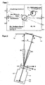
- a film camera in which the stabilization device according to the invention can be used in a preferred manner is shown in Figure 2 schematically from above and in total denoted by 10.
- the film camera has a housing 12, in which the stabilizing device according to the invention arranged together with other components is.
- the optics of the film camera 10 is simplified schematically represented and designated 14.
- the optics 14 defines a constructive optical axis of the film camera 10, which is designated M in FIG.
- the constructive optical axis M in turn defines one below as an actual image section 16 designated image detail. Conveniently, the axis M is at the center this actual image section addressed.
- Target image section is the image detail, the desired by the user. Ie. this one wants this Target image section 18, or its displacement movement, maintained for a certain period of time or for any length of time.
- the appropriate target orientation of the camera in The following also called effective optical axis, is with Z designated.
- Z In the time shown in Figure 1 is the Film camera 10 along its constructive optical axis M, which is different from the original orientation Z differs by a position difference angle R.
- the size of this angle is determined by the user caused by targeted alignment of the camera position difference plus one of the inevitable trembling and Varying of the user caused interference angle.
- the actual horizon of the film camera is determined by the axis M and defines an axis perpendicular thereto K, where through these two axes again spanned a plane is.
- the camera 10 may have another compensating device designated 20 for compensation of the position difference between actual horizon and target horizon, below H designated to have.
- the compensation device 20 is provided here in the image plane 22 of the camera 10 and compensates the horizon difference z. B. by means of appropriate Rotation of the electronic image sensor.
- the position-direction difference R illustrated in FIG is only by a pivoting movement of the film camera 10 causes the intersection of the axes M, Z.
- linear deviations have to be considered, i.e. substantially perpendicular to the target image detail defining axis Z. Such deviations are referred to below as P.
- FIG. 1 shows a preferred embodiment of an im Frame of the device according to the invention usable viewfinder image shown.
- the axis Z is here in the Center of the viewfinder image.
- geometric figures, which in the present embodiment are formed as circles are different Position difference ranges definable, each of which different Functions are assignable.
- the deviation between the axes Z and M is preferably a directional cursor C1 z.
- This area preferably corresponds to one Position difference value range of e.g. 0.7 degrees around the target orientation the optical axis.
- the area function is executed when the directional cursor C1 enters the circle R1 is controlled and held there. She then holds the Target orientation constant, which means a standstill of the image section equivalent.
- the analog range function "Change the current orientation movement" is assigned, which preferably works as follows: the target orientation is first in the direction in which the cursor C1 the circle R1 leaves. Once the cursor is outside for a minimum time of R1, a vector is determined, and preferably as Arrow V is displayed, from the district center to the circle shows. From this moment the position difference range R1 but it will still be displayed.
- the length and direction of the arrow V are a measure of the size and direction of the current target displacement speed the desired image detail, these preferably taking into account the current image angle the optics measured in image section widths per second becomes.
- the arrow length is preferably approximately proportional to the logarithm of the current setpoint speed, where the initial speed is zero or is very low.
- the arrowhead is controlled in any direction and in that way direction and speed the movement of the target image section changed.
- the arrowhead does not follow the cursor C1 directly, but somewhat delayed in time.
- the greater the distance the cursor C1 from the arrowhead is the faster they are tracked so that they are never far from the Cursor C1 removed.
- the below described range R2 only the distance between cursor and range limit of R2.
- the target image section analogous to the camera orientation in any Direction and be relocated at any speed, this shift because of the applied Acceleration algorithms sensitively possible.
- the camera may waver while running during However, this analog range function is not completely suppressed since it is the modification of the velocity vector influenced with.
- an alignment difference range R2 provided. He will be at the helm of the Velocity vector V preferably in the form of a Circle R2 shown, whose radius is preferably variable and equal to half the arrow length, but he expediently not greater than a predetermined maximum value R2m should be dimensioned.
- the discrete range function associated with area R2 is executed when the alignment cursor C1 in this Circle R2 is controlled.
- the area function then stops the instantaneous setpoint speed and setpoint direction of Image section shift constant as long as the cursor is held in this circle R2.
- the display of area R2 may preferably be on request omitted if instead e.g. the cursor C1 on approach to the (now invisible) circle edge or to its Exceeding its color and / or blinking frequency etc. changes accordingly.
- This variable in its position range is that of the user by controlling the cursor C1 in the area always near the cursor R2 in an intuitive way an acceleration of a Image Close-up Motion and into a Uniform Movement can be transferred.
- a position cursor C2 reflects the deviation of the reference point of the image pickup device from a desired position the environment. The impact of this distance with their unavoidable fluctuations should prevail everything considered in extreme telephoto and from the compensation device can be compensated.
- a discrete range function for stabilizing the camera position variations and a position difference range assigned to it which e.g. in the form of a circle P1 in the center of the viewfinder image whose area is a position difference value range from e.g. 8 cm diameter corresponds.
- P1 falls for the sake of oversight with the Circle R1 together.
- the range function passes size and direction of this difference, as already described above, to the compensation device. It will be executed if a e.g. represented by a small square Position cursor C2 by moving the image pickup device to the side and in height in the area P1 controlled and held there.
- P1 preferably during recording breaks a essential assigned a smaller value range, which has the advantage C2 is always close to the center when recording starts from P1 lies.
- the cursor C2 is outside the position difference range P1 in the remaining area P2, the deviation becomes to the reference point of the environment according to an algorithm always again returned to the range limit P1. This matches with moving to the target image detail marking Serving position reference point of the environment with the camera.
- a horizon cursor C3 reflects the deviation of the camera horizon from the target horizon. He will preferably indicated by 2 short lines on the searcher display border, the on an imaginary, going through the display center, Line whose position is analogous to the angle between the Camera horizon and the target horizon is, with the target horizon preferably always horizontally through the viewfinder image center runs.
- a discrete range function for a provided to the real horizon parallel target horizon position It is executed when the horizon cursor C3 means Align the camera around its optical axis in the corresponding position difference range H1 on the viewfinder screen edge is controlled and held there. This area includes e.g. an angle of + - 3 degrees to the desired horizon.
- the Range function then sets the desired image horizon angle to zero. This is then by the compensation device automatically the displayed image horizon parallel to held real horizon, and then its location from shaking and swaying the camera is no longer affected.
- an analog domain function intended for a change in the target horizon position.
- the Rotation and the rotation speed of the target horizon should preferably be about the rotation of the camera around her follow optical axis.
- This analog range function is executed when the horizon cursor C3 is turned of the image pickup device about its optical axis from the belonging to the current horizon position horizon difference area is controlled out. It then changes the target horizon angle the faster, the farther the cursor C3 of the range H1 or H2 is removed. During the execution this analog range function is the wavering the camera with in the movement of the image horizon.
- a discrete range function for a constant maintenance of the current desired horizon position intended is done when the Cursor C3 by aligning the camera with its optical Axis in the corresponding position difference range H2 am Viewfinder image edge controlled and held there. This Area H2 will not change until the nominal horizon of the Ambient horizon displayed.
- the position difference range is preferably on the left and / or right of the viewfinder image center and includes e.g. an angle of + - 2 degrees.
- the discrete range function then holds the current setpoint horizon angle constant. Then automatically the displayed image horizon held parallel to the desired horizon, being its location from the shaking and swaying of the image capture device is not affected.
- position difference areas and discrete range functions for a horizontal or vertical pivot are preferably as described below, by selecting a menu, activated, at the same time the desired maximum swivel speed can be preselected.
- the pivoting preferably starts in the direction in which the cursor C1 is the central area for Picture standstill leaves, with the direction of movement of the Image section on horizontal or vertical movement is limited.
- the start-up is preferably carried out with a constant Acceleration until the preselected swing speed is reached.
- the outlet also takes place with same deceleration acceleration when the cursor returns is led into the central area. After a stop the normal position difference ranges are activated again.
- an alignment difference area is activated and displayed which is preferably over the whole Display extends and its range function the current Movement of the image section keeps constant.
- Such Button can z. B. at a suitable location of the housing be provided of the image pickup device.
- This area are more labeled or with symbols Alignment difference areas superimposed, their area functions System parameters of the image acquisition device, such as white balance, color temperature, gray filter, aperture, Exposure time, activation of position difference ranges with selection of a maximum speed for one Pan, etc. control, if by means of appropriate Aligning the image pickup device selected and e.g. when the key is released.
- an alignment difference range activatable whose boundaries visually superimposed on the viewfinder image and include a substantial part of the viewfinder image and its range function on the one hand the current movement of the image section holds constant and the other running from the position difference indicated by a cursor under evaluation of the current focal length of the optics corresponding image section position determined and on a focusing automatic for focusing on this Forward the part of the image section.
- the rest Alignment difference area is during the key press preferably an analog range function for Relocation of the image section assigned.
- the following are functions for pre-programming and program-controlled execution of an image section progression for movie cameras.
- the pictured image section is completely still, as long as the target position does not change and as long the position difference not that of the compensation device exceeds compensatable values.
- a first position difference range in the form of a cone with e.g. at an angle of 2 degrees the desired position of the optical axis given and this Area assigned the task "Image Cutting Standstill". As long as the position difference values within this Area, the target position data are not changed.
- a second position difference range is defined, that from all the rest of the compensation device compensable position difference values, and this area the task "shifting of the image section" assigned.
- the Target position data changed according to an algorithm in the especially direction and distance of the current position difference regarding the first position difference range.
- the greater the distance to the range limit the larger the speed of the target image shift. This happens preferably after an exponential relationship: at a positional difference of e.g. 2, 3, 4, or 5 degrees relative the target position is the speed of the desired position change then e.g. to 0, 1, 10, or 100 degrees per second set.
- For a positional difference of e.g. 3 degrees to the right of Target image center then becomes the horizontal component of Target position data continuously increased by 1 degree per second.
- the notification of the position difference e.g. realized as follows: To the viewfinder image around, for example, eight arrows are visualized, point their point to the viewfinder image center. These arrows can be in their color and / or brightness and / or flashing frequency are modulated, giving the user from the type of representation of the reference of the position difference to the position difference ranges e.g. as follows is made: as long as the position difference values in the central first position difference range A, the arrows are static green. Their brightness reflects the size and direction of the current position difference value contrary. For a zero position difference all shine Arrows equal to light. For a positional difference of e.g.
- the right arrow shines brighter, the others Arrows correspondingly darker.
- the position difference approaches the range limit of 2 degrees, then the corresponding Arrow yellow and optionally also flashing shown. If the position difference has exceeded the range limit, the corresponding arrow is displayed in red.
- the arrows in the green or keep yellow area are quiet resting and to achieve a non-fluctuating image detail.
- the user also determines when the image section should relocate. For this he aims the binoculars as long after e.g. right until the right arrow turns red, after which the image section starts to move to the right. This happens the faster the faster he does that Binoculars moved to the right. Because with this simple variant the invention, the speed of the image section displacement for speeds greater than zero always depends on the momentary size of the position difference, can not optimally stabilize the frame moving movement done what with binoculars but also not of great importance. Once by appropriate Align the binoculars the arrows back into the green or yellow area are controlled, takes place immediate and overshoot-free picture standstill.
- this simple variant of the invention can also for a film camera recording on chemical film or for a consumer video camera.
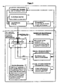
- FIG. 3 is a functional diagram of a simple embodiment an image stabilization according to the invention shown.
- Alignment of the optical axis takes into account what for Consumer binoculars or consumer video cameras quite can be sufficient because of unwanted movements of the optical Axis by far the biggest impact on the Have rest.
- the possible consideration of the position of the imaging device and the horizon position accordingly, d. H. it can each be the same Function diagram are applied.
- 301 sets the target alignment of the optical axis, by z. B. corresponding directional values in a Memory are stored. Their initial value can be arbitrary here be, z. B. 30 degrees East and 10 degrees below the horizon.
- the actual Position of the optical axis determined.
- z. B. a Gyro be used.
- a rotation about the vertical axis of the image pickup device the value of orientation with respect to the direction of the compass changes and a rotation about the transverse axis of the imaging device the value concerning the inclination to the horizon.
- the position difference between actual position and Target position determined and converted in both components, which are compensated by the compensation device can, for. B. in the two angles to be compensated the vertical axis and the transverse axis of the image pickup device.
- the compensation device 304 then compensates for the alignment difference completely and for all frequencies one changing alignment difference, as above already mentioned.
- the core of the invention consists of the area 311 to 315. From a system controller 312, there are two position difference ranges (311) fixed: a central area LDB-1 of 2 degrees around the nominal direction of the optical Axis and remaining area LDB-2 between 2 degrees and 5 degrees around the desired direction of the optical axis.
- the system control is constantly watching in which area the instantaneous alignment difference of the optical axis falls.
- the position difference with respect to Range limits to the user via the message facility 313 communicated so that the user by means of according to the alignment of the image recording device, the position difference steer specifically into one of the areas and there can hold.
- the analogue Range function 315 "displacement / movement" of the target orientation the optical axis called and executed, which the current target orientation of the optical axis the faster the position difference of the limit of the range LDB-2 is removed, the Direction of change from the direction of the position difference is derived to the center of LDB-1.
- the nominal position follows hereby analogous to the orientation of the image recording device. Unintended fluctuations of the position difference, however, go as in conventional solutions, with in the displacement speed one.
- this range feature is used also arbitrary position initial values at commissioning of the image pickup device with non-compensable Position difference values synchronized, since every large position difference tracking the target position at high speed, so that the position difference automatically in the shortest possible time Time is reduced to compensatable values.
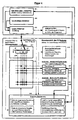
- FIG. 4 is a functional diagram of a more complex one Embodiment of an image stabilization according to the invention, for z. A professional movie camera, shown. In the further description is only on the Differences from the embodiment according to Figure 3 received:
- the main difference is that there are more than two Position difference ranges (five examples here), where some of them are variable in their position and size, such as B.
- This Area is first activated by the system control 415, if the position difference is the central area LDB-2 has left for "image standstill". His situation and that Its range of values is preferably a function of speed and direction of the current displacement speed the desired image position, as previously described.
- the area function 422 is executed, which is the Target coordinates of the target image position, according to the Call of 422 existing target displacement speed, evenly and steadily changed. This uniform movement of the target image section is then completely free from all unwanted position difference fluctuations. This is due to the always present complete compensation of all position difference values Of course, synonymous for the captured image.
- a graphic display 418 with graphic display the position difference ranges LDB 1, 2, 3, 4 ... in the form graphic symbols and graphic display of the position difference provided in the form of cursors (see also description of FIGS. 1 and 2).
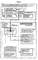
- FIG. 5 shows a functional diagram of a device according to the invention Image stabilization shown, which shows how conventional stabilization devices even without redesign can be modified to the benefits to use the invention.
- Image stabilization shown, which shows how conventional stabilization devices even without redesign can be modified to the benefits to use the invention.
- a conventional stabilizer device is 501 to 505 of group 500.
- this of the position difference range LDB-1 assigned Range function 514 for "image standstill" during the Execution of this feature simply disabled, so he the target image position then no longer changed. The picture section is then unaffected by location fluctuations quiet.
- FIG. 6 shows a functional diagram of a device according to the invention Image stabilization shown, which shows how another variant of a conventional stabilization device be modified without redesign can to take advantage of the invention.
- Image stabilization shown, which shows how another variant of a conventional stabilization device be modified without redesign can to take advantage of the invention.
- a conventional stabilizer device is 603 to 605 of group 600.
- the image section then remains unaffected by Location fluctuations in its movement.
Landscapes
- Engineering & Computer Science (AREA)
- Multimedia (AREA)
- Signal Processing (AREA)
- Studio Devices (AREA)
- Adjustment Of Camera Lenses (AREA)
Priority Applications (5)
| Application Number | Priority Date | Filing Date | Title |
|---|---|---|---|
| EP03027791A EP1553758A1 (fr) | 2003-12-03 | 2003-12-03 | Appareil optique avec dispositif stabilisateur d'image avec affichage de la correction effectuée |
| US11/003,871 US7907174B2 (en) | 2003-12-03 | 2004-12-03 | Stabilization device for image stabilization and associated methods |
| PCT/EP2004/013798 WO2005055589A1 (fr) | 2003-12-03 | 2004-12-03 | Dispositif de stabilisation pour une stabilisation d'image et deplacement de partie d'image stabilisee |
| CNB2004800354091A CN100382574C (zh) | 2003-12-03 | 2004-12-03 | 用于使图像稳定及使稳定图像部分移动的稳定设备 |
| JP2006541913A JP4489081B2 (ja) | 2003-12-03 | 2004-12-03 | 画像を安定させまた安定させた画像セクションを変位させるための安定化装置 |
Applications Claiming Priority (1)
| Application Number | Priority Date | Filing Date | Title |
|---|---|---|---|
| EP03027791A EP1553758A1 (fr) | 2003-12-03 | 2003-12-03 | Appareil optique avec dispositif stabilisateur d'image avec affichage de la correction effectuée |
Publications (1)
| Publication Number | Publication Date |
|---|---|
| EP1553758A1 true EP1553758A1 (fr) | 2005-07-13 |
Family
ID=34585875
Family Applications (1)
| Application Number | Title | Priority Date | Filing Date |
|---|---|---|---|
| EP03027791A Withdrawn EP1553758A1 (fr) | 2003-12-03 | 2003-12-03 | Appareil optique avec dispositif stabilisateur d'image avec affichage de la correction effectuée |
Country Status (5)
| Country | Link |
|---|---|
| US (1) | US7907174B2 (fr) |
| EP (1) | EP1553758A1 (fr) |
| JP (1) | JP4489081B2 (fr) |
| CN (1) | CN100382574C (fr) |
| WO (1) | WO2005055589A1 (fr) |
Cited By (1)
| Publication number | Priority date | Publication date | Assignee | Title |
|---|---|---|---|---|
| EP2952953A1 (fr) | 2014-06-04 | 2015-12-09 | MBDA Deutschland GmbH | Procédé d'alignement d'un système de caméra sur un objet cible et système de caméra |
Families Citing this family (13)
| Publication number | Priority date | Publication date | Assignee | Title |
|---|---|---|---|---|
| JP4832013B2 (ja) * | 2005-07-05 | 2011-12-07 | 富士フイルム株式会社 | 像振れ補正装置 |
| JP4750047B2 (ja) * | 2006-03-31 | 2011-08-17 | 株式会社リコー | 位置ずれ検出装置、位置ずれ検出方法、位置ずれ検出プログラムおよび記録媒体 |
| JP4717701B2 (ja) * | 2006-04-24 | 2011-07-06 | キヤノン株式会社 | 撮像システム、撮影方向制御方法、及びプログラム |
| US8330824B2 (en) * | 2007-11-09 | 2012-12-11 | Panasonic Corporation | Camera, camera system, and camera body |
| GB0806871D0 (en) * | 2008-04-15 | 2008-05-21 | Vitec Group Plc The | Improvements in or relating to methods of stabilising optical apparatus |
| JP5431083B2 (ja) * | 2009-09-16 | 2014-03-05 | オリンパスイメージング株式会社 | 撮影装置および撮影装置の制御方法 |
| US8699868B1 (en) | 2013-03-14 | 2014-04-15 | Microsoft Corporation | Anti-shake correction system for curved optical sensor |
| US9692975B2 (en) * | 2013-04-10 | 2017-06-27 | Microsoft Technology Licensing, Llc | Motion blur-free capture of low light high dynamic range images |
| US9817243B2 (en) | 2015-01-27 | 2017-11-14 | Microsoft Technology Licensing, Llc | Imaging apparatus |
| US10123004B2 (en) * | 2016-01-28 | 2018-11-06 | Olympus Corporation | Image stabilization apparatus and image pickup apparatus using image stabilization apparatus |
| CN105827958A (zh) * | 2016-03-17 | 2016-08-03 | 广东欧珀移动通信有限公司 | 控制方法、控制装置及电子装置 |
| FR3050814B1 (fr) * | 2016-04-29 | 2019-06-07 | Airbus Helicopters | Procede et dispositif d'aide a la visee pour le guidage laser d'un projectile |
| CH716570A2 (de) * | 2019-09-09 | 2021-03-15 | Andre Reber | Verfahren zur Verbesserung der Sehfähigkeit einer sehbehinderten Person mit einer portablen Sehhilfe. |
Citations (7)
| Publication number | Priority date | Publication date | Assignee | Title |
|---|---|---|---|---|
| JPH0383459A (ja) * | 1989-08-28 | 1991-04-09 | Fuji Photo Film Co Ltd | ビデオカメラ |
| US5282044A (en) | 1990-10-18 | 1994-01-25 | Fuji Photo Film Co., Ltd. | Camera shake correction system |
| JPH10307309A (ja) | 1997-05-06 | 1998-11-17 | Canon Inc | 像ぶれ補正装置 |
| US5886744A (en) | 1995-09-08 | 1999-03-23 | Intel Corporation | Method and apparatus for filtering jitter from motion estimation video data |
| US6069656A (en) | 1997-12-17 | 2000-05-30 | Raytheon Company | Method and apparatus for stabilization of images by closed loop control |
| JP3083459B2 (ja) | 1994-10-27 | 2000-09-04 | ユニ・チャーム株式会社 | 生理用ナプキン |
| US6445411B1 (en) | 1997-03-14 | 2002-09-03 | Canon Kabushiki Kaisha | Camera control system having anti-blur facility |
Family Cites Families (23)
| Publication number | Priority date | Publication date | Assignee | Title |
|---|---|---|---|---|
| US886744A (en) * | 1908-01-23 | 1908-05-05 | Lorenzo Ullo | Car-vestibule. |
| US4774589A (en) | 1986-03-03 | 1988-09-27 | Rowland David A | Optical system image stabilizer employing electromechanical torque sensors |
| JP2704963B2 (ja) | 1988-11-07 | 1998-01-26 | キヤノン株式会社 | 像ぶれ状態表装置及びそのための制御装置 |
| US5266985A (en) * | 1990-07-16 | 1993-11-30 | Nikon Corporation | Camera with optimum composition determinator |
| JP3250245B2 (ja) * | 1992-01-23 | 2002-01-28 | キヤノン株式会社 | 防振カメラ |
| JPH0644005A (ja) * | 1992-01-24 | 1994-02-18 | Seiko Instr Inc | 座標入力装置 |
| JPH05216104A (ja) | 1992-02-06 | 1993-08-27 | Nikon Corp | 流し撮り装置 |
| DE69324620T2 (de) * | 1992-02-06 | 1999-12-02 | Nikon Corp., Tokio/Tokyo | Photoapparat mit Detektor für panoramische Aufnahme |
| JPH05249529A (ja) * | 1992-03-06 | 1993-09-28 | Nikon Corp | 手ブレ防止カメラ |
| JP3412238B2 (ja) * | 1993-03-31 | 2003-06-03 | 株式会社ニコン | 構図アドバイス機能を備えたカメラ |
| JPH07110501A (ja) * | 1993-10-13 | 1995-04-25 | Nikon Corp | ブレ防止カメラ |
| JPH07114054A (ja) * | 1993-10-15 | 1995-05-02 | Nikon Corp | ブレ防止カメラ |
| JP3513950B2 (ja) * | 1993-12-14 | 2004-03-31 | 株式会社ニコン | 像振れ補正カメラ |
| JPH08223471A (ja) * | 1995-02-14 | 1996-08-30 | Techno Kapura:Kk | 電子画像カメラおよびその画像ぶれ防止方法 |
| US5794078A (en) * | 1995-09-11 | 1998-08-11 | Nikon Corporation | Image movement correction of camera |
| JP3639672B2 (ja) | 1996-06-03 | 2005-04-20 | キヤノン株式会社 | 撮像装置及び方法 |
| JP3864456B2 (ja) | 1996-07-08 | 2006-12-27 | シーアイ化成株式会社 | 化粧シート |
| JPH10161171A (ja) * | 1996-11-29 | 1998-06-19 | Minolta Co Ltd | ブレ補正装置 |
| JP3424468B2 (ja) * | 1996-11-29 | 2003-07-07 | ミノルタ株式会社 | ブレ補正装置及びカメラ |
| JPH10161177A (ja) | 1996-12-04 | 1998-06-19 | Minolta Co Ltd | カメラの露出制御装置 |
| JP3899584B2 (ja) | 1997-04-02 | 2007-03-28 | ソニー株式会社 | 画像振れ補正装置および方法 |
| JP3242878B2 (ja) | 1998-03-23 | 2001-12-25 | 日本碍子株式会社 | リチウム二次電池 |
| JP2001042379A (ja) * | 1999-07-27 | 2001-02-16 | Olympus Optical Co Ltd | ぶれ検出カメラ |
-
2003
- 2003-12-03 EP EP03027791A patent/EP1553758A1/fr not_active Withdrawn
-
2004
- 2004-12-03 WO PCT/EP2004/013798 patent/WO2005055589A1/fr active Application Filing
- 2004-12-03 CN CNB2004800354091A patent/CN100382574C/zh not_active Expired - Fee Related
- 2004-12-03 US US11/003,871 patent/US7907174B2/en not_active Expired - Fee Related
- 2004-12-03 JP JP2006541913A patent/JP4489081B2/ja not_active Expired - Fee Related
Patent Citations (7)
| Publication number | Priority date | Publication date | Assignee | Title |
|---|---|---|---|---|
| JPH0383459A (ja) * | 1989-08-28 | 1991-04-09 | Fuji Photo Film Co Ltd | ビデオカメラ |
| US5282044A (en) | 1990-10-18 | 1994-01-25 | Fuji Photo Film Co., Ltd. | Camera shake correction system |
| JP3083459B2 (ja) | 1994-10-27 | 2000-09-04 | ユニ・チャーム株式会社 | 生理用ナプキン |
| US5886744A (en) | 1995-09-08 | 1999-03-23 | Intel Corporation | Method and apparatus for filtering jitter from motion estimation video data |
| US6445411B1 (en) | 1997-03-14 | 2002-09-03 | Canon Kabushiki Kaisha | Camera control system having anti-blur facility |
| JPH10307309A (ja) | 1997-05-06 | 1998-11-17 | Canon Inc | 像ぶれ補正装置 |
| US6069656A (en) | 1997-12-17 | 2000-05-30 | Raytheon Company | Method and apparatus for stabilization of images by closed loop control |
Cited By (2)
| Publication number | Priority date | Publication date | Assignee | Title |
|---|---|---|---|---|
| EP2952953A1 (fr) | 2014-06-04 | 2015-12-09 | MBDA Deutschland GmbH | Procédé d'alignement d'un système de caméra sur un objet cible et système de caméra |
| DE102014008385A1 (de) * | 2014-06-04 | 2015-12-17 | Mbda Deutschland Gmbh | Verfahren zum Ausrichten eines Kamerasvstems auf ein Zielobjekt und Kamerasystem |
Also Published As
| Publication number | Publication date |
|---|---|
| US7907174B2 (en) | 2011-03-15 |
| CN100382574C (zh) | 2008-04-16 |
| CN1886982A (zh) | 2006-12-27 |
| JP4489081B2 (ja) | 2010-06-23 |
| JP2007513373A (ja) | 2007-05-24 |
| US20050168582A1 (en) | 2005-08-04 |
| WO2005055589A1 (fr) | 2005-06-16 |
Similar Documents
| Publication | Publication Date | Title |
|---|---|---|
| DE602005001189T2 (de) | Bildstabilisator mit automatischer Deaktivierung bei beabsichtigten Kamerabewegungen | |
| DE69123926T2 (de) | System zum Korrigieren von Kamerazittern | |
| EP1553758A1 (fr) | Appareil optique avec dispositif stabilisateur d'image avec affichage de la correction effectuée | |
| DE69233439T2 (de) | Überwachungsvorrichtung mit Steuerung der Kamera und der Linsenmontage | |
| DE102014204905B4 (de) | Bildaufnahmevorrichtung und zugehöriges Steuerverfahren | |
| DE19942900B4 (de) | Vorrichtung zur Korrektur von Bildfehlern, die durch ein Kameraverwackeln hervorgerufen werden | |
| DE69319677T2 (de) | Vorrichtung zur Ausgleichung von Bildzittern | |
| DE10152883B4 (de) | Nachführvorrichtung | |
| DE2025877C3 (de) | Sichtgerät | |
| DE102004008714A1 (de) | Objektivsteuersystem und Fokusinformations-Anzeigevorrichtung | |
| EP3534210B1 (fr) | Unité d'affichage à réglage du foyer | |
| DE69231926T2 (de) | Verhinderung von durch Kameraverwackelungen verursachten unscharfen Bildern | |
| DE10012629B4 (de) | Ferngesteuertes Schwenkkopfsystem | |
| DE69634868T2 (de) | Bildaufnahmegerät mit Funktion zur Verhinderung von Vibrationen | |
| DE10338249B4 (de) | Autofokusvorrichtung unter Verwendung des Verhältnisses zweier Fokusauswertungswerte an Positionen unterschiedlicher Lichtweglängen | |
| EP3204813A1 (fr) | Microscope avec diaphragme à iris à adaptation automatique | |
| WO2007025661A1 (fr) | Procede pour prendre une image et camera a images animees | |
| DE69720902T2 (de) | Bildstabilisierungsvorrichtung | |
| EP3857303A1 (fr) | Procédé de réglage de mise au point d'une caméra | |
| DE102022109398A1 (de) | Autofokus-Verfahren und zugehöriges optisches Abbildungssystem | |
| DE102006048006A1 (de) | Verfahren und Vorrichtung zur Steuerung einer schwenkbaren Kamera | |
| EP1455525A1 (fr) | Procédé et dispositif d'enregistrement des données vidéo | |
| EP3908874A1 (fr) | Système optique pour former une image d'un objet et procédé permettant de faire fonctionner le système optique | |
| EP1434184B1 (fr) | Commande d'un système multicaméra | |
| EP2424225B1 (fr) | Système de détection d'image et procédé destiné à la détection d'un objet |
Legal Events
| Date | Code | Title | Description |
|---|---|---|---|
| PUAI | Public reference made under article 153(3) epc to a published international application that has entered the european phase |
Free format text: ORIGINAL CODE: 0009012 |
|
| 17P | Request for examination filed |
Effective date: 20040903 |
|
| AK | Designated contracting states |
Kind code of ref document: A1 Designated state(s): AT BE BG CH CY CZ DE DK EE ES FI FR GB GR HU IE IT LI LU MC NL PT RO SE SI SK TR |
|
| AX | Request for extension of the european patent |
Extension state: AL LT LV MK |
|
| AKX | Designation fees paid |
Designated state(s): AT BE BG CH CY CZ DE DK EE ES FI FR GB GR HU IE IT LI LU MC NL PT RO SE SI SK TR |
|
| 17Q | First examination report despatched |
Effective date: 20060228 |
|
| GRAP | Despatch of communication of intention to grant a patent |
Free format text: ORIGINAL CODE: EPIDOSNIGR1 |
|
| GRAJ | Information related to disapproval of communication of intention to grant by the applicant or resumption of examination proceedings by the epo deleted |
Free format text: ORIGINAL CODE: EPIDOSDIGR1 |
|
| GRAP | Despatch of communication of intention to grant a patent |
Free format text: ORIGINAL CODE: EPIDOSNIGR1 |
|
| GRAP | Despatch of communication of intention to grant a patent |
Free format text: ORIGINAL CODE: EPIDOSNIGR1 |
|
| INTG | Intention to grant announced |
Effective date: 20140625 |
|
| GRAS | Grant fee paid |
Free format text: ORIGINAL CODE: EPIDOSNIGR3 |
|
| STAA | Information on the status of an ep patent application or granted ep patent |
Free format text: STATUS: THE APPLICATION IS DEEMED TO BE WITHDRAWN |
|
| 18D | Application deemed to be withdrawn |
Effective date: 20150701 |