EP1553405A2 - Inspektionsmaschine - Google Patents
Inspektionsmaschine Download PDFInfo
- Publication number
- EP1553405A2 EP1553405A2 EP05005396A EP05005396A EP1553405A2 EP 1553405 A2 EP1553405 A2 EP 1553405A2 EP 05005396 A EP05005396 A EP 05005396A EP 05005396 A EP05005396 A EP 05005396A EP 1553405 A2 EP1553405 A2 EP 1553405A2
- Authority
- EP
- European Patent Office
- Prior art keywords
- bottles
- machine according
- inspection machine
- beam paths
- optical axis
- Prior art date
- Legal status (The legal status is an assumption and is not a legal conclusion. Google has not performed a legal analysis and makes no representation as to the accuracy of the status listed.)
- Granted
Links
Images


Classifications
-
- B—PERFORMING OPERATIONS; TRANSPORTING
- B07—SEPARATING SOLIDS FROM SOLIDS; SORTING
- B07C—POSTAL SORTING; SORTING INDIVIDUAL ARTICLES, OR BULK MATERIAL FIT TO BE SORTED PIECE-MEAL, e.g. BY PICKING
- B07C5/00—Sorting according to a characteristic or feature of the articles or material being sorted, e.g. by control effected by devices which detect or measure such characteristic or feature; Sorting by manually actuated devices, e.g. switches
- B07C5/04—Sorting according to size
- B07C5/12—Sorting according to size characterised by the application to particular articles, not otherwise provided for
- B07C5/122—Sorting according to size characterised by the application to particular articles, not otherwise provided for for bottles, ampoules, jars and other glassware
-
- G—PHYSICS
- G01—MEASURING; TESTING
- G01N—INVESTIGATING OR ANALYSING MATERIALS BY DETERMINING THEIR CHEMICAL OR PHYSICAL PROPERTIES
- G01N21/00—Investigating or analysing materials by the use of optical means, i.e. using sub-millimetre waves, infrared, visible or ultraviolet light
- G01N21/84—Systems specially adapted for particular applications
- G01N21/88—Investigating the presence of flaws or contamination
- G01N21/90—Investigating the presence of flaws or contamination in a container or its contents
-
- B—PERFORMING OPERATIONS; TRANSPORTING
- B07—SEPARATING SOLIDS FROM SOLIDS; SORTING
- B07C—POSTAL SORTING; SORTING INDIVIDUAL ARTICLES, OR BULK MATERIAL FIT TO BE SORTED PIECE-MEAL, e.g. BY PICKING
- B07C5/00—Sorting according to a characteristic or feature of the articles or material being sorted, e.g. by control effected by devices which detect or measure such characteristic or feature; Sorting by manually actuated devices, e.g. switches
- B07C5/04—Sorting according to size
- B07C5/12—Sorting according to size characterised by the application to particular articles, not otherwise provided for
- B07C5/122—Sorting according to size characterised by the application to particular articles, not otherwise provided for for bottles, ampoules, jars and other glassware
- B07C5/126—Sorting according to size characterised by the application to particular articles, not otherwise provided for for bottles, ampoules, jars and other glassware by means of photo-electric sensors, e.g. according to colour
-
- B—PERFORMING OPERATIONS; TRANSPORTING
- B07—SEPARATING SOLIDS FROM SOLIDS; SORTING
- B07C—POSTAL SORTING; SORTING INDIVIDUAL ARTICLES, OR BULK MATERIAL FIT TO BE SORTED PIECE-MEAL, e.g. BY PICKING
- B07C5/00—Sorting according to a characteristic or feature of the articles or material being sorted, e.g. by control effected by devices which detect or measure such characteristic or feature; Sorting by manually actuated devices, e.g. switches
- B07C5/34—Sorting according to other particular properties
- B07C5/3404—Sorting according to other particular properties according to properties of containers or receptacles, e.g. rigidity, leaks, fill-level
- B07C5/3408—Sorting according to other particular properties according to properties of containers or receptacles, e.g. rigidity, leaks, fill-level for bottles, jars or other glassware
-
- B—PERFORMING OPERATIONS; TRANSPORTING
- B07—SEPARATING SOLIDS FROM SOLIDS; SORTING
- B07C—POSTAL SORTING; SORTING INDIVIDUAL ARTICLES, OR BULK MATERIAL FIT TO BE SORTED PIECE-MEAL, e.g. BY PICKING
- B07C5/00—Sorting according to a characteristic or feature of the articles or material being sorted, e.g. by control effected by devices which detect or measure such characteristic or feature; Sorting by manually actuated devices, e.g. switches
- B07C5/34—Sorting according to other particular properties
- B07C5/3416—Sorting according to other particular properties according to radiation transmissivity, e.g. for light, x-rays, particle radiation
-
- G—PHYSICS
- G01—MEASURING; TESTING
- G01N—INVESTIGATING OR ANALYSING MATERIALS BY DETERMINING THEIR CHEMICAL OR PHYSICAL PROPERTIES
- G01N21/00—Investigating or analysing materials by the use of optical means, i.e. using sub-millimetre waves, infrared, visible or ultraviolet light
- G01N21/84—Systems specially adapted for particular applications
- G01N21/88—Investigating the presence of flaws or contamination
- G01N21/90—Investigating the presence of flaws or contamination in a container or its contents
- G01N21/9036—Investigating the presence of flaws or contamination in a container or its contents using arrays of emitters or receivers
Definitions
- the invention relates to an inspection machine for fürbrollbare bottles or the like. According to the preamble of Claim 1.
- Beverage bottling lines become such inspection machines used to be damaged or dirty before filling Recognize bottles and excrete.
- To check the Sidewall area of the bottles are inspection systems Known for taking a picture of the bottle side wall a continuous rotation of the bottles around their vertical axis require. While the rotary motion is being used by the Image pickup device, e.g. Line scan camera, essentially only the center of the bottle along a vertical line added.
- the product obtained by this transaction procedure Picture of a bottle sidewall is characterized by a high Recording quality, since virtually no optical Distortions due to the sidewall curvature occur.
- the invention starting from the last mentioned prior art, the object of a Inspection device for sidewall inspection of bottles or the like, which requires little effort and provides a good picture quality.
- Particularly advantageous is a mirror arrangement, the same long beam paths from the sidewall area of a test to be tested Bottle to the image recording device (CCD camera) supplies. This can ensure that the of the individual beam paths delivered the same size are causing difficulties in image analysis be avoided.
- CCD camera image recording device
- a particularly compact design is by a in the Claims 12 and 13 specified embodiment of Inspection device allows.
- the inspection station can have another Image recording device (CCD camera) for controlling the Contour, height or color of the inspection station be assigned to passing bottles.
- This second Image pickup device can be positioned so that you Beam path also the crossing of the Beam path of the sidewall control cuts, causing advantageously by only one control the Image recording of both image recording devices simultaneously is triggerable.
- FIG. 1 Top view is recognizable, the bottles to be tested. 5 by a continuously driven feed conveyor 14 of the Inspection machine supplied.
- the through the feed conveyor 14, e.g. a plate conveyor, in a closed row upright transported bottles 5 are through Guide railing 30 on a parallel, with increased speed synchronous to the feed conveyor 14 driven conveyor belt 4 transferred, wherein by the Speed jump Gaps or intermediate distances in the Bottle flow can be generated. These intervals are necessary to carry out the sidewall inspection.
- the side wall control is performed by a on the conveyor belt 4th arranged inspection station 1, consisting essentially of a diffuse light emitting screen 2, a Camera 3 and between the conveyor belt 4 and the camera. 3 arranged mirrors for generating the beam paths 6, 7th and 8 is.
- the inspection station 1 with a second camera 15 for contour, height and / or Color detection equipped.
- Seen in the conveying direction behind the inspection station 1 is a controllable Ejector device 31 on one side of the conveyor belt 4th placed, the opposite a collecting container 32nd assigned. With the ejector device 31, e.g.
- the control of the two cameras 3, 15 and the Ejector 31 takes place under consideration of Conveying speed through one of the inspection station 1 upstream trigger light barrier 33.
- the inspection station 1 for sidewall inspection is In addition, a second inspection station 40 downstream.
- This inspection station the bottles 5 by two arranged opposite, synchronous to the conveyor belt. 4 drivable belt 41 laterally on the lateral surface trapped and ground free over several Inspection devices for ground, mouth control or Residual fluid detection to be transported. To Completion of these inspection operations will be the bottles of parked the belt 41 on a subsequent conveyor belt 45 and released.
- Behind the second inspection station 40 is again a controllable ejector device 46 with a arranged opposite to the conveyor belt 45 Tray 47 placed to pass through the first or second Inspection station 1, 40 recognized as not reusable Bottles, e.g. with outbreaks at the mouth, excrete to can. Behind it is a third ejector device 48 for discharging possibly after a new cleaning continue to use bottles on a parallel to the Conveyor belt 45 arranged arranged conveyor 49.
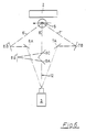
- the two Beam paths 6 and 7 are to the optical axis 12 of the camera 3 symmetrically formed or arranged. Accordingly are also the optical path 7 forming mirrors 7a and 7b symmetrical to the mirrors 6a and 6b of the beam path 6 positioned.
- the two mirrors 6b and 7b are so aligned with each other, that the beam paths 6 and 7 at a certain angle, e.g. 60 degrees, based on the Central axes 6 'and 7' of the beam paths, in one above the Conveyor 4 meeting intersection area 9 meet.
- the mirror 8c is like that positioned so that the illustrated in Fig. 2 vertical Projection of the central axis 8 'at the common Interface 10 of the three central axes 6 ', 7' and 8 'both normal to the line of symmetry 11 of the bottle to be tested 5 as is also aligned to the conveying direction of the conveyor belt 4.
- the responsible for the sidewall control Camera 3 is with equipped with a surface array on which the three Beam paths 6, 7 and 8 are shown side by side.
- the camera 3 is an evaluation device, not shown associated with the image taken by the camera evaluated programmatically.
- the evaluation program can do this be designed that of each beam path only the middle image area is evaluated while the Border areas can be hidden or ignored in order to Inaccuracies in the peripheral areas of the recorded Images due to the optical distortions to the strong to avoid curved bottle edges.
- the inspection station 1 is a second camera 15 to control the contour and / or height and / or color of assigned to bottles to be tested.
- This second camera 15 is arranged so that their beam path 16 unhindered between the mirrors of the sidewall control device through a bottle 5 located in the crossing region 9 can meet.
- the optical axis 17 of the Camera 15 aligned so that they also through the common interface 10 of the three beam paths 6, 7 and 8 of the sidewall control runs.
- This is the two Cameras 3 and 15 with a common control signal for Simultaneous image acquisition controllable. Very cheap is an arrangement of the beam path 16 of the camera 15, at the vertical projection of the optical axis 17 the vertical projection of the central axis 8 'and the optical Axis 12 of the camera 3 with an angle of about 25 degrees crosses.
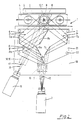
- Fig. 2 In the side view of Fig. 2 shown in Fig. 3 are for the sake of clarity, only the camera 3 and the both the beam path 7 associated mirror 7a and 7b shown. Shown is the beam path of the in Fig. 2 with 7 'designated center axis.
- the positioning the plane mirrors 7a and 7b (and also the other mirrors) is done by two spaced apart parallel, respectively Positioning plates 21 lying in a horizontal plane, by spacer rods 22 on a base plate 19th are attached.
- the positioning plates 21 have the thickness and width of the mirror corresponding slots (see Fig. 2).
- the mirrors are through these slots from above insertable and stand with their lower edge on the Base plate 19. This is in the event of damage easy and quick exchange of mirrors possible.
- a guide 20th attached to the vertically arranged camera 3 is held vertically adjustable by means of a clamping piece 35.
- the clamp also has a pivot 36 for Adjustment of the angle of incidence of the optical axis 12 of the Camera 3 on the underneath on the base plate 19th arranged mirror 13.
- Fig. 5 corresponds largely to Fig. 4, wherein in addition, the camera 15 for contour and height detection with its beam path 16 is indicated. Because of the vertical Arrangement of the camera 15 is also a the beam path 16 from the vertical direction transverse to the symmetry line 11 the bottle to be tested 5 deflecting mirror 18th required.
- the second camera 15 is not in shown manner, similar to the camera 3, at the top Positioning plate 21 adjustable attached.
- Fig. 6 shows an alternative mirror arrangement for Generation of the sidewall control required Beam paths.
- the illustrated mirror assembly generates also two to the optical axis 12 of the camera. 3 symmetrically formed beam paths 6 and 7, of which only the central axes 6 'and 7' are shown.
- the with a sufficient distance to the optical axis 12 are arranged, such that the third beam path 8 forming mirror 8A, B, C before the aforementioned mirrors the two remaining beam paths can be placed, and the leading to the bottle 5 section of the beam path. 8 between the belonging to the beam paths 6 to 7 Mirroring can pass through unhindered.
- the inspection machine shown in Fig. 7 has basically the same mechanical structure as the Inspection machine according to Fig. 1. In addition, it has via an inspection station 100 for a second Sidewall inspection of the bottles 5.
- This inspection station 100 is immediately behind the belt 41 of Inspection station 40 arranged on the conveyor belt 45.
- the Mirror arrangement of the inspection station 100 agrees with the the inspection station 1 match.
- Both belts 41 are driven in synchronism with the conveyor belts 4 and 45, but with a low speed difference to each other.
- Depending on the set Speed difference will be the bottles during the Transfer from the conveyor belt 4 on the conveyor belt 45 to a certain angle, preferably about 90 degrees to their The vertical axis turned and then without rotation by itself guided the inspection station 100.
- the Excretion of unusable bottles 5 are made, as previously explained for Fig. 1 has already been explained.
- the speed difference between the two belts 41 is adjustable so that when changing the Inspection machine on bottles with another Peripheral measure of the rotation angle of the bottles when passing through the Belt length is constant 90 degrees.
- one of the two belts 41 drivingly with the conveyor belts 4 and / or 45 connected during the second belt 41 via its own, controllable drive with a programmable controller.
- the conversion of the Translation ratio between the two belts 41 can then done by pressing a button.
- a sidewall inspection with two inspection stations 1 and 100 has the advantage that the necessary intermediate distances can be kept small in the bottle stream, which also the bottle transport speed at a given Performance is lower than with a control of the whole Bottle side wall with only one inspection station. This is on the smaller angle between the rays 6 and 7 which can be chosen, e.g. 60 degrees, there the bottle sidewall when passing one of the two Inspection stations 1 and 100 are not complete must be recorded. In addition, arise by the smaller angle optical advantages in image acquisition. at a sidewall control with only a single Inspection station, however, is between the beams 6 and 7 an angle of over 100 degrees for complete detection a bottle sidewall required.
Landscapes
- General Health & Medical Sciences (AREA)
- Health & Medical Sciences (AREA)
- Chemical & Material Sciences (AREA)
- Physics & Mathematics (AREA)
- Analytical Chemistry (AREA)
- Biochemistry (AREA)
- Life Sciences & Earth Sciences (AREA)
- General Physics & Mathematics (AREA)
- Immunology (AREA)
- Pathology (AREA)
- Toxicology (AREA)
- Investigating Materials By The Use Of Optical Means Adapted For Particular Applications (AREA)
- Analysing Materials By The Use Of Radiation (AREA)
Abstract
Description
- Fig. 1
- eine schematische Draufsicht auf eine Inspektionsmaschine mit einer Inspektionsstation zur Seitenwandkontrolle,
- Fig. 2
- eine vergrößerte Darstellung der Inspektionsstation zur Seitenwandkontrolle nach Fig. 1,
- Fig. 3
- eine erste Seitenansicht der Inspektionsstation nach Fig. 2 in Flaschenförderrichtung betrachtet,
- Fig. 4
- eine zweite Seitenansicht der Inspektionsstation nach Fig. 2 in Förderrichtung der Flaschen betrachtet,
- Fig. 5
- eine dritte Seitenansicht der Inspektionsstation nach Fig. 2 in Förderrichtung der Flaschen betrachtet,
- Fig. 6
- eine schematische Draufsicht auf eine Inspektionsstation zur Seitenwandkontrolle mit einer von der Fig. 2 abweichenden Spiegelanordnung und
- Fig. 7
- eine schematische Draufsicht auf eine Inspektionsmaschine mit zwei Inspektionsstationen zur Seitenwandkontrolle von Flaschen.
Claims (25)
- inspektionsmaschine für durchleuchtbare Flaschen (5) oder dgl., mit einer Inspektionsstation (1) zur Seitenwandkontrolle, die eine Beleuchtungseinrichtung (2), eine Bildaufnahmeeinrichtung (3) und eine zwischengeordnete, wenigstens zwei Strahlengänge erzeugende Spiegelanordnung aufweist, sowie einer die Flaschen (5) einspurig durch die Strahlengänge führenden Transporteinrichtung (4), gekennzeichnet durch eine Spiegelanordnung (6a, 6b, 7a, 7b, 8a, 8b, 8c), die wenigstens drei, aus verschiedenen Richtungen auf die Seitenwand einer zu prüfenden Flasche (5) aufteffende Strahlengänge (6, 7, 8) erzeugt.
- Inspektionsmaschine nach Anspruch 1, dadurch gekennzeichnet, daß sich alle Strahlengänge (6, 7, 8) in einem gemeinsamen Kreuzungsbereich (9) schneiden, durch den die Flaschen (5) mittels der Transporteinrichtung (4) hindurchführbar sind.
- Inspektionsmaschine nach wenigstens einem der vorhergehenden Ansprüche, dadurch gekennzeichnet, daß sich die Mittelachsen (6', 7', 8') aller Strahlengänge (6, 7, 8) an einer gemeinsamen Schnittstelle (10) treffen und die Flaschen (5) mittels der Transporteinrichtung (4) durch die Schnittstelle (10) führbar sind, insbesondere derart, daß die Symmetrielinie (11) der Flaschen in etwa die Schnittstelle (10) passiert und im Augenblick des Zusammentreffens der Symmetrielinie mit dieser Schnittstelle die Bildaufnahme erfolgt.
- Inspektionsmaschine nach wenigstens einem der vorhergehenden Ansprüche, dadurch gekennzeichnet, daß alle Strahlengänge (6, 7, 8) gleich lang sind, insbesondere die Mittelachsen (6', 7', 8') der Strahlengänge von der Bildaufnahmeeinrichtung (3) bis zu einer gemeinsamen Schnittstelle (10) eine übereinstimmende Länge, vorzugsweise im Bereich von 750 bis 1500 mm, insbesondere 1240 mm, aufweisen.
- Inspektionsmaschine nach wenigstens einem der vorhergehenden Ansprüche, dadurch gekennzeichnet, daß die optische Achse (12) der Bildaufnahmeeinrichtung (3) sowohl normal zur Transportrichtung der Flaschen in der Inspektionsstation (1) als auch zumindest abschnittsweise quer zur Symmetrielinie (11) der Flaschen (5) ausgerichtet ist.
- Inspektionsmaschine nach einem der vorhergehenden Ansprüche, dadurch gekennzeichnet, daß zwei Strahlengänge (6, 7) symmetrisch zur optischen Achse (12) der Bildaufnahmeeinrichtung (3) ausgebildet sind, die Strahlengänge vorzugsweise jeweils durch zwei zwischen der Bildaufnahmeeinrichtung (3) und der Beleuchtungseinrichtung (2) angeordnete Spiegel (6a, 6b und 7a, 7b) umgelenkt werden, derart, daß die Strahlengänge (6, 7), ausgehend von der Bildaufnahmeeinrichtung, zunächst durch ein erstes Paar von Spiegeln (6a, 7a) von der optischen Achse (12) wegweisend und durch ein nachgeordnetes zweites Paar von Spiegeln (6b, 7b) zur optischen Achse (12) hinweisend auf den Seitenwandbereich einer zu prüfenden Flasche (5) gerichtet werden, wobei die Schnittstelle (10) der Mittelachsen (6', 7') der Strahlengänge insbesondere auf der optischen Achse (12) der Bildaufnahmeeinrichtung (3) liegt.
- Inspektionsmaschine nach wenigstens einem der vorhergehenden Ansprüche, dadurch gekennzeichnet, daß zwischen zwei symmetrisch verlaufenden Strahlengängen (6, 7) ein dritter; vorzugsweise mittig ausgerichteter Strahlengang (8) angeordnet ist, wobei dessen Mittelachse (8') zumindest abschnittsweise, mit der optischen Achse (12) der Bildaufnahmeeinrichtung (3) fluchtet.
- Inspektionsmaschine nach wenigstens einem der vorhergehenden Ansprüche, dadurch gekennzeichnet, daß ein dritter Strahlengang (8) durch zwei auf der optischen Achse (12) der Bildaufnahmeeinrichtung (3) liegende Spiegel (8a, 8c) und einen zwischengeschalteten, neben der optischen Achse (12) angeordneten Spiegel (8b) umgelenkt wird, wobei der neben der optischen Achse positionierte Spiegel (8b) den Strahlengang (8) vom ersten auf den zweiten der beiden auf der optischen Achse liegenden Spiegel (8a, 8c) umlenkt.
- Inspektionsmaschine nach wenigstens einem der vorhergehenden Ansprüche 6 bis 8, dadurch gekennzeichnet, daß die dem dritten Strahlengang (8) zugeordneten Spiegel (8A, 8B, 8C) - von der Bildaufnahmeeinrichtung 3 zur Beleuchtungseinrichtung 2 gesehen - vor den Spiegeln (6A, 6B, 7A, 7B) der symmetrisch verlaufenden Strahlengänge (6, 7) angeordnet sind.
- Inspektionsmaschine nach wenigstens einem der vorhergehenden Ansprüche, dadurch gekennzeichnet, daß zumindest der auf die Seitenwand einer Flasche auftreffende Abschnitt eines dritten Strahlenganges (8) durch einen Zwischenraum zwischen den den übrigen Strahlengängen (6, 7) zugeordneten Spiegeln (6A, 6B, 7A, 7B) hindurchtreten kann.
- Inspektionsmaschine nach wenigstens einem der vorhergehenden Ansprüche, dadurch gekennzeichnet, daß ein einem dritten Strahlengang (8) zugeordneter Spiegel (8a) vor einem ersten Paar von Spiegeln (6a, 7a) zweier symmetrisch verlaufender Strahlengänge (6, 7) angeordnet ist und ein weiterer Spiegel (8c) dahinter.
- Inspektionsmaschine nach wenigstens einem der vorhergehenden Ansprüche, dadurch gekennzeichnet, daß die optische Achse (12) der Bildaufnahmeeinrichtung (3) abschnittsweise im wesentlichen parallel zur Symmetrielinie (11) der Flaschen (5) ausgerichtet ist und die optische Achse (12) -ausgehend von der Bildaufnahmeeinrichtung (3)- durch einen Spiegel (13) quer zur Symmetrielinie (11) der Flaschen (5) umgelenkt wird.
- Inspektionsmaschine nach Anspruch 12, dadurch gekennzeichnet, daß die Bildaufnahmeeinrichtung (3) seitlich neben der Transporteinrichtung (4) mit Abstand oberhalb deren Förderebene angeordnet ist.
- Inspektionsmaschine nach wenigstens einem der vorhergehenden Ansprüche, dadurch gekennzeichnet, daß zwei Strahlengänge (6, 7) in einem Winkelbereich von 45 bis 80 Grad, insbesondere 60 Grad, bezogen auf ihre Mittelachsen (6', 7'), zueinander ausgerichtet auf eine zu prüfende Flasche (5) treffen.
- Inspektionsmaschine nach Anspruch 14, dadurch gekennzeichnet, daß ein dritter Strahlengang (8) -den von den übrigen Strahlengängen (6, 7) eingeschlossenen Winkel halbierend- auf eine zu prüfende Flasche (5) trifft.
- Inspektionsmaschine nach wenigstens einem der vorhergehenden Ansprüche, dadurch gekennzeichnet, daß die Inspektionsstation (1) eine zweite Bildaufnahmeeinrichtung (15) zur Kontur- und/oder Höhenund/oder Farberkennung der Flaschen (5) aufweist, wobei deren Strahlengang (16) durch den Kreuzungsbereich (9) der Strahlengänge (6, 7, 8) der Seitenwandkontrolle verläuft, insbesondere die optische Achse (17) im wesentlichen durch die Schnittstelle (10) der Mittelachsen (6', 7', 8') der Strahlengänge der Seitenwandkontrolle verläuft, so daß die Bildaufnahme einer Flasche durch beide Bildaufnahmeeinrichtungen (3, 15) in etwa zeitgleich erfolgen kann.
- Inspektionsmaschine nach Anspruch 16, dadurch gekennzeichnet, daß die optische Achse (17) der zweiten Bildaufnahmeeinrichtung (15) abschnittsweise im wesentlichen parallel zur Symmetrielinie (11) der Flaschen (5) verläuft und durch einen Spiegel (18) quer zur Symmetrielinie (11) der Flaschen (5) umgelenkt wird.
- Inspektionsmaschine nach wenigstens einem der Ansprüche 16 oder 17, dadurch gekennzeichnet, daß die quer zur Symmetrielinie (11) der Flaschen (5) zusammenlaufenden Abschnitte der optischen Achsen (12, 17) der Bildaufnahmeeinrichtungen (3, 15) einen spitzen Winkel im Bereich von vorzugsweise 15 bis 35 Grad, insbesondere 25 Grad, einschließen.
- Inspektionsmaschine nach wenigstens einem der vorhergehenden Ansprüche, dadurch gekennzeichnet, daß die Spiegel (6a, 6b, 7a, 7b, 8a, 8b, 8c, 13) auf einer gemeinsamen Grundplatte (19) stehend angeordnet sind.
- Inspektionsmaschine nach Anspruch 19, dadurch gekennzeichnet, daß die Spiegel (6a, 6b, 7a, 7b, 8a, 8b, 8c) durch parallel angeordnete, mit Schlitzen ausgestattete Positionierplatten (21) gehalten werden.
- Inspektionsmaschine nach wenigstens einem der vorhergehenden Ansprüche, dadurch gekennzeichnet, daß die Bildaufnahmeeinrichtungen (3, 15) eine Flächenmatrix besitzen, wobei insbesondere die Strahlengänge (6, 7, 8) der Seitenwandkontrolle nebeneinander auf der Flächenmatrix der Sildaufnahmeeinrichtung (3) abgebildet werden.
- Inspektionsmaschine nach wenigstens einem der vorhergehenden Ansprüche, dadurch gekennzeichnet, daß die Bildaufnahme durch elektronische Kameras, insbesondere CCD-Kameras, erfolgt.
- Inspektionsmaschine nach wenigstens einem der vorhergehenden Ansprüche, dadurch gekennzeichnet, daß die Flaschen (5) zur Seitenwandkontrolle nacheinander zwei Inspektionsstationen (1, 100) in unterschiedlichen Drehstellungen durchlaufen.
- Inspektionsmaschine nach Anspruch 23, dadurch gekennzeichnet, daß zwischen den Inspektionsstationen (1, 100) eine Vorrichtung zum Drehen der Flaschen (5) angeordnet ist, vorzugsweise bestehend aus zwei gegenüberliegend an der Mantelfläche der Flaschen angreifenden Riemen (41), die mit unterschiedlicher Geschwindigkeit synchron zur Transporteinrichtung (4) antreibbar sind.
- Inspektionsmaschine nach Anspruch 24, dadurch gekennzeichnet, daß zwischen den an den Flaschen angreifenden Riemen (41) eine Geschwindigkeitsdifferenz zur Drehung der Flaschen einstellbar ist, derart, daß bei einer Umstellung auf Flaschen mit einem anderen Umfangsmaß der Drehwinkel der Flaschen beim Durchlaufen der Riemen (41) konstant bleibt.
Applications Claiming Priority (5)
| Application Number | Priority Date | Filing Date | Title |
|---|---|---|---|
| DE19939311405 DE9311405U1 (de) | 1993-07-30 | 1993-07-30 | Inspektionsmaschine |
| DE9311405U | 1993-07-30 | ||
| DE9313115U | 1993-09-01 | ||
| DE19939313115 DE9313115U1 (de) | 1993-09-01 | 1993-09-01 | Inspektionsmaschine |
| EP94924822A EP0663069B1 (de) | 1993-07-30 | 1994-07-29 | Inspektionsmaschine |
Related Parent Applications (2)
| Application Number | Title | Priority Date | Filing Date |
|---|---|---|---|
| EP94924822A Division EP0663069B1 (de) | 1993-07-30 | 1994-07-29 | Inspektionsmaschine |
| EP94924822.3 Division | 1995-02-09 |
Publications (3)
| Publication Number | Publication Date |
|---|---|
| EP1553405A2 true EP1553405A2 (de) | 2005-07-13 |
| EP1553405A3 EP1553405A3 (de) | 2005-09-07 |
| EP1553405B1 EP1553405B1 (de) | 2011-03-30 |
Family
ID=25961073
Family Applications (3)
| Application Number | Title | Priority Date | Filing Date |
|---|---|---|---|
| EP01112238A Expired - Lifetime EP1130384B1 (de) | 1993-07-30 | 1994-07-29 | Inspektionsmaschine |
| EP94924822A Expired - Lifetime EP0663069B1 (de) | 1993-07-30 | 1994-07-29 | Inspektionsmaschine |
| EP05005396A Expired - Lifetime EP1553405B1 (de) | 1993-07-30 | 1994-07-29 | Inspektionsmaschine |
Family Applications Before (2)
| Application Number | Title | Priority Date | Filing Date |
|---|---|---|---|
| EP01112238A Expired - Lifetime EP1130384B1 (de) | 1993-07-30 | 1994-07-29 | Inspektionsmaschine |
| EP94924822A Expired - Lifetime EP0663069B1 (de) | 1993-07-30 | 1994-07-29 | Inspektionsmaschine |
Country Status (7)
| Country | Link |
|---|---|
| US (1) | US5729340A (de) |
| EP (3) | EP1130384B1 (de) |
| JP (1) | JP3604388B2 (de) |
| KR (1) | KR950703733A (de) |
| BR (1) | BR9405536A (de) |
| DE (3) | DE59410287D1 (de) |
| WO (1) | WO1995004267A1 (de) |
Cited By (1)
| Publication number | Priority date | Publication date | Assignee | Title |
|---|---|---|---|---|
| WO2021219959A1 (fr) * | 2020-04-30 | 2021-11-04 | Tiama | Installation et procédé pour assurer la mise au point simultanée de systèmes optiques en fonction du diamètre des récipients |
Families Citing this family (55)
| Publication number | Priority date | Publication date | Assignee | Title |
|---|---|---|---|---|
| GB9416406D0 (en) * | 1994-08-13 | 1994-10-05 | Univ Of Huddersfield | Colour inspection system |
| AU9315498A (en) * | 1997-10-10 | 1999-05-03 | Northeast Robotics Llc | Imaging method and system with elongate inspection zone |
| US5895911A (en) * | 1998-01-22 | 1999-04-20 | Emhart Glass S.A. | Glass container body check detector |
| AU742980B2 (en) * | 1999-10-13 | 2002-01-17 | Kawasaki Jukogyo Kabushiki Kaisha | Random work arranging device |
| DE10027226C1 (de) | 2000-05-31 | 2001-10-18 | Krones Ag | Verfahren und Vorrichtung zum Inspizieren transparenter Behälter |
| DE10164058B4 (de) * | 2000-12-30 | 2008-06-12 | Krones Ag | Inspektionsvorrichtung |
| KR20010079284A (ko) * | 2001-07-02 | 2001-08-22 | 서용교 | 거울을 이용한 잡곡용 색채선별기 |
| KR20030011175A (ko) * | 2001-07-28 | 2003-02-07 | 삼성전자주식회사 | 납땜검사장치 |
| KR20030046616A (ko) * | 2001-12-06 | 2003-06-18 | 삼성전자주식회사 | 레이져 광 산란을 이용한 고순도 글래스 튜브의 미세 기포분석 장치 |
| DE10339473A1 (de) * | 2003-08-27 | 2005-03-24 | Seidenader Maschinenbau Gmbh | Vorrichtung zur Prüfung von Erzeugnissen |
| DE102004013774B4 (de) | 2004-03-20 | 2018-10-04 | Khs Gmbh | Inspektionsvorrichtung für Behälter aus Glas oder einem transluzenten Material |
| FR2873206B1 (fr) | 2004-07-13 | 2007-11-23 | Iris Inspection Machines Sa | Machine pour detecter des defauts d'un objet transparent ou translucide |
| DE102005017957A1 (de) * | 2005-04-18 | 2006-10-26 | Khs Ag | Inspektionsvorrichtung |
| DE102005023534B4 (de) * | 2005-05-21 | 2007-04-12 | Krones Ag | Vorrichtung zum Inspizieren etikettierter Gefäße |
| DE102005036796A1 (de) * | 2005-08-02 | 2007-02-08 | Krones Ag | Vorrichtung und Verfahren zum Erkennen von Flascheneigenschaften |
| DE202005020478U1 (de) * | 2005-12-30 | 2007-05-24 | Krones Ag | Vorrichtung zum Inspizieren von Etiketten auf Gefäßen |
| JP4809168B2 (ja) * | 2006-09-19 | 2011-11-09 | アサヒ飲料株式会社 | ボトル容器検査装置 |
| US7626158B2 (en) * | 2006-10-23 | 2009-12-01 | Emhart Glass S.A. | Machine for inspecting glass containers |
| DE102007020460B3 (de) * | 2007-04-27 | 2009-01-08 | Krones Ag | Inspektionsvorrichtung und Inspektionsverfahren für Behältnisse |
| DE102007025524B4 (de) * | 2007-05-31 | 2010-07-29 | Khs Ag | Opto-elektrisches Erfassungssystem |
| DE102007036621A1 (de) | 2007-07-31 | 2009-02-05 | Miho Inspektionssysteme Gmbh | Verfahren und Vorrichtung zur Untersuchung von Flaschen aus Kunststoff oder Glas auf vorgewählte Eigenschaften |
| JP5298327B2 (ja) * | 2008-08-26 | 2013-09-25 | キリンテクノシステム株式会社 | 異物検査装置及び異物検査システム |
| DE102008063076B3 (de) * | 2008-12-24 | 2010-04-29 | Krones Ag | Flascheninspektionsvorrichtung mit abbildungskorrigiertem Spiegelkabinett |
| DE102009020919A1 (de) * | 2009-05-12 | 2010-11-18 | Krones Ag | Vorrichtung zum Erkennen von Erhebungen und/oder Vertiefungen auf Flaschen, insbesondere in einer Etikettiermaschine |
| DE102010004972A1 (de) * | 2010-01-18 | 2011-07-21 | Krones Ag, 93073 | Vorrichtung und Verfahren zum Inspizieren von Behältnissen |
| GB2482473A (en) * | 2010-06-29 | 2012-02-08 | Constar Internat Uk Ltd | Inspection of articles |
| WO2012061441A1 (en) * | 2010-11-01 | 2012-05-10 | Make-All Corporation | Raised vial stopper detection system |
| DE102011004584A1 (de) * | 2011-02-23 | 2012-08-23 | Krones Aktiengesellschaft | Verfahren und Vorrichtung zum Erkennen von Blasen und/oder Falten auf etikettierten Behältern |
| AT510849B1 (de) * | 2011-06-28 | 2012-07-15 | Medek & Schoerner Gmbh | Vorrichtung zur optischen erfassung von objekten |
| DE102011083037A1 (de) | 2011-09-20 | 2013-03-21 | Krones Aktiengesellschaft | Verfahren und Vorrichtung zur Inspektion von Behältern und Vorformlingen |
| DE102012009783B3 (de) * | 2012-05-18 | 2013-08-14 | Khs Gmbh | Verfahren und Vorrichtung zur Inspektion von Leerflaschen |
| EP2910480A4 (de) * | 2012-10-04 | 2016-07-13 | Fuji Seal Int Inc | Behälter mit schrumpfsitzetikett, schrumpfsitzetikett und herstellungsverfahren für behälter mit schrumpfsitzetikett |
| DE102014102450A1 (de) * | 2014-02-25 | 2015-08-27 | Khs Gmbh | Inspektionsvorrichtung mit inverser Folienlinse |
| DE102014104078B4 (de) | 2014-03-25 | 2019-04-25 | Krones Ag | Inspektionsvorrichtung und Inspektionsverfahren zur Durchlichtinspektion von Behältern |
| DE102014106380A1 (de) | 2014-05-07 | 2015-11-12 | Krones Ag | Verfahren und Vorrichtung zum Transport von Behältern |
| DE102014216188A1 (de) * | 2014-08-14 | 2016-02-18 | Krones Ag | Optisches Inspektionsverfahren und optische Inspektionsvorrichtung für Behälter |
| DE102015204412A1 (de) | 2015-03-11 | 2016-09-15 | Krones Ag | Inspektionsvorrichtung zum Inspizieren von Flaschen |
| DE102015218356A1 (de) * | 2015-09-24 | 2017-03-30 | Krones Ag | Inspektionsverfahren und -vorrichtung zur optischen Durchlichtinspektion von unetikettierten Behältern |
| US20170244904A1 (en) * | 2016-02-18 | 2017-08-24 | The Boeing Company | Optical monitoring system and method for imaging a component under test |
| PL3208782T3 (pl) | 2016-02-22 | 2023-04-24 | Wincor Nixdorf International Gmbh | Przyrząd do przyjmowania opakowań zwrotnych |
| WO2017204766A2 (en) | 2016-05-26 | 2017-11-30 | Turkiye Sise Ve Cam Fabrikalari A. S. | A quality control system for semi-finished glass products |
| WO2017204765A2 (en) | 2016-05-26 | 2017-11-30 | Turkiye Sise Ve Cam Fabrikalari A. S. | A quality control system for household glass products |
| FR3056296B1 (fr) * | 2016-09-19 | 2018-10-19 | Tiama | Installation pour l'inspection optique de recipients en verre en sortie de machine de formage |
| DE102017201776B4 (de) | 2017-02-03 | 2023-03-09 | Krones Ag | Inspektionsvorrichtung und -verfahren zur Seitenwand- und Verschlusskopfinspektion von Behältern |
| DE102017206971A1 (de) | 2017-04-26 | 2018-10-31 | Krones Aktiengesellschaft | Inspektionsverfahren und -vorrichtung zur bildverarbeitenden Inspektion von Behältern |
| UY38287A (es) | 2018-07-30 | 2019-08-30 | Grifols Worldwide Operations Ltd | Procedimiento y dispositivo para detectar defectos en el cierre de viales encapsulados |
| EP3715835B1 (de) * | 2019-03-29 | 2024-11-06 | Pharmacontrol Electronic GmbH | Inspektionssystem |
| CN110006598B (zh) * | 2019-04-24 | 2024-03-12 | 山东省科学院海洋仪器仪表研究所 | 一种西林瓶在线检漏装置及检漏方法 |
| US11047803B1 (en) * | 2020-09-10 | 2021-06-29 | Applied Vision Corporation | Glass container inspection system |
| CA3198276A1 (en) * | 2020-11-24 | 2022-06-02 | Joe Chan | Systems and methods for blow-fill-seal (bfs) product inspection |
| DE102021115493A1 (de) * | 2021-06-15 | 2022-12-15 | Heuft Systemtechnik Gmbh | Verfahren und Vorrichtung zur Vollbehälterinspektion |
| DE102021115729A1 (de) * | 2021-06-17 | 2022-12-22 | Krones Aktiengesellschaft | Vorrichtung und Verfahren zum Inspizieren von befüllten Behältnissen und deren Füllgut |
| IT202200001496A1 (it) * | 2022-01-28 | 2023-07-28 | Marco Lottici | Apparato e metodo per l’ispezione di contenitori, in particolare bottiglie in vetro con collo filettato |
| US12454422B2 (en) * | 2022-08-22 | 2025-10-28 | Industrial Dynamics Company, Ltd. | Hybrid starwheel system for inspecting an empty bottle |
| CN119124035A (zh) * | 2024-10-30 | 2024-12-13 | 广东艾特易仪器设备有限公司 | 一种pet空瓶或玻璃空瓶外轮廓和瓶口尺寸测量系统及方法 |
Family Cites Families (17)
| Publication number | Priority date | Publication date | Assignee | Title |
|---|---|---|---|---|
| GB977059A (en) * | 1960-01-28 | 1964-12-02 | Emi Ltd | Improvements relating to optical inspection apparatus |
| US3932042A (en) * | 1974-05-20 | 1976-01-13 | Barry-Wehmiller Company | Container inspection apparatus and method of inspection |
| US4025201A (en) * | 1975-04-21 | 1977-05-24 | Ball Brothers Service Corporation | Method and apparatus for video inspection of articles of manufacture by decussate paths of light |
| GB1600400A (en) * | 1977-10-13 | 1981-10-14 | Ti Fords Ltd | Bottle inspection apparatus |
| JPS5546172A (en) * | 1978-09-29 | 1980-03-31 | Kirin Brewery Co Ltd | Detector for foreign material |
| ES500718A0 (es) * | 1980-03-28 | 1982-05-16 | Udaras Na Gaeltachta | Un aparato para inspeccionar recipientes translucidos |
| DE3035077A1 (de) * | 1980-09-17 | 1982-04-22 | Siemens AG, 1000 Berlin und 8000 München | Verfahren und anordnung zur pruefung transparenter behaelter auf verunreinigungen oder beschaedigungen |
| US4553217A (en) * | 1981-07-08 | 1985-11-12 | Ball Corporation | Glassware gauging system |
| US4500203A (en) * | 1982-09-30 | 1985-02-19 | Owens-Illinois, Inc. | Method and apparatus for inspecting articles |
| US4509081A (en) * | 1982-11-29 | 1985-04-02 | Industrial Automation Corp. | Optical system for automatic sorting and inspection equipment |
| US4586080A (en) * | 1984-03-22 | 1986-04-29 | Ball Corporation | Method and apparatus for video inspection of articles of manufacture |
| US4691231A (en) * | 1985-10-01 | 1987-09-01 | Vistech Corporation | Bottle inspection system |
| JPH0799326B2 (ja) * | 1986-08-30 | 1995-10-25 | 株式会社マキ製作所 | 球塊状物品の外観検査方法と装置 |
| US4751386A (en) * | 1987-03-31 | 1988-06-14 | Emhart Industries, Inc. | Lean detector for determining the offset of an axis of symmetry of a container from its norm |
| US4958223A (en) * | 1988-09-16 | 1990-09-18 | Owens-Brockway Glass Container Inc. | Inspection of container finish |
| JP2944092B2 (ja) * | 1989-01-27 | 1999-08-30 | 株式会社マキ製作所 | 物品の外観検査装置 |
| US5256871A (en) * | 1992-12-22 | 1993-10-26 | Emhart Glass Machinery Investments Inc. | Machine for video inspection of glass containers with intersecting light beams |
-
1994
- 1994-07-29 BR BR9405536-0A patent/BR9405536A/pt not_active Application Discontinuation
- 1994-07-29 JP JP50557295A patent/JP3604388B2/ja not_active Expired - Lifetime
- 1994-07-29 EP EP01112238A patent/EP1130384B1/de not_active Expired - Lifetime
- 1994-07-29 KR KR1019950700954A patent/KR950703733A/ko not_active Withdrawn
- 1994-07-29 DE DE59410287T patent/DE59410287D1/de not_active Expired - Lifetime
- 1994-07-29 US US08/406,911 patent/US5729340A/en not_active Expired - Lifetime
- 1994-07-29 DE DE59410463T patent/DE59410463D1/de not_active Expired - Lifetime
- 1994-07-29 DE DE59410415T patent/DE59410415D1/de not_active Expired - Lifetime
- 1994-07-29 WO PCT/EP1994/002523 patent/WO1995004267A1/de not_active Ceased
- 1994-07-29 EP EP94924822A patent/EP0663069B1/de not_active Expired - Lifetime
- 1994-07-29 EP EP05005396A patent/EP1553405B1/de not_active Expired - Lifetime
Non-Patent Citations (1)
| Title |
|---|
| None |
Cited By (3)
| Publication number | Priority date | Publication date | Assignee | Title |
|---|---|---|---|---|
| WO2021219959A1 (fr) * | 2020-04-30 | 2021-11-04 | Tiama | Installation et procédé pour assurer la mise au point simultanée de systèmes optiques en fonction du diamètre des récipients |
| FR3109820A1 (fr) * | 2020-04-30 | 2021-11-05 | Tiama | Installation et procédé pour assurer la mise au point simultanée de systèmes optiques en fonction du diamètre des récipients |
| US12092586B2 (en) | 2020-04-30 | 2024-09-17 | Tiama | Apparatus and method for simultaneously focusing optical systems according to the diameter of the containers |
Also Published As
| Publication number | Publication date |
|---|---|
| EP1553405B1 (de) | 2011-03-30 |
| EP1130384A1 (de) | 2001-09-05 |
| BR9405536A (pt) | 1999-09-08 |
| JP3604388B2 (ja) | 2004-12-22 |
| EP0663069A1 (de) | 1995-07-19 |
| US5729340A (en) | 1998-03-17 |
| EP1553405A3 (de) | 2005-09-07 |
| KR950703733A (ko) | 1995-09-20 |
| EP1130384A8 (de) | 2001-12-05 |
| EP1130384B1 (de) | 2003-05-14 |
| WO1995004267A1 (de) | 1995-02-09 |
| DE59410415D1 (de) | 2005-12-08 |
| JPH08505947A (ja) | 1996-06-25 |
| EP0663069B1 (de) | 2005-11-02 |
| DE59410463D1 (de) | 2011-05-12 |
| DE59410287D1 (de) | 2003-06-18 |
Similar Documents
| Publication | Publication Date | Title |
|---|---|---|
| EP0663069B1 (de) | Inspektionsmaschine | |
| EP0836093B1 (de) | Verfahren und Anordnung zur optischen Schweissnahtprüfung | |
| EP0415154B2 (de) | Verfahren zum Inspizieren von Gegenständen aus unterschiedlichen Blickwinkeln | |
| EP0338376B1 (de) | Verfahren zum optischen Abtasten von Markierungen auf Gegenständen und Vorrichtung zu seiner Durchführung | |
| EP0433666B1 (de) | Vorrichtung zur dreidimensionalen Inspektion von Hohlkörpern | |
| DE4417015A1 (de) | Sortierautomat zur Sortierung bzw. Klassifikation von Kleinprodukten der pharmazeutischen und der Süßwarenindustrie nach Form und Farbe | |
| DE2256736B2 (de) | Meßanordnung zur automatischen Prüfung der Oberflächenbeschaffenheit und Ebenheit einer Werkstückoberfläche | |
| WO2013045131A1 (de) | Vorrichtung und verfahren zum ausrichten von behältern | |
| EP0847187B1 (de) | Abtastvorrichtung zur bildelementweisen fotoelektrischen Ausmessung eines Messobjekts | |
| DE2617457A1 (de) | Verfahren zum erzeugen eines sichtbildes eines zu pruefenden gegenstandes mittels durchstrahlung sowie optische pruefvorrichtung | |
| DE2338295C2 (de) | Vorrichtung zum Feststellen von Fehlern auf gegenüberliegenden Flächen einer im wesentlichen ebenen Bahn | |
| EP1606579B1 (de) | Mantelflächensensor sowie abbildungsoptik hierfür | |
| DE9313115U1 (de) | Inspektionsmaschine | |
| EP0708325B1 (de) | Verfahren und Vorrichtung zur Inspektion von Gegenständen, insbesondere von Flaschen | |
| EP0349823A1 (de) | Verfahren und Vorrichtung zur Überprüfung von Zigaretten | |
| DE2903529A1 (de) | Verfahren zum messen von entfernungen und vorrichtung zur durchfuehrung des verfahrens | |
| DE9311405U1 (de) | Inspektionsmaschine | |
| EP0270062B1 (de) | Bildaufnahmevorrichtung | |
| DE29919761U1 (de) | Inspektionsmaschine | |
| DE4401020A1 (de) | Verfahren zur Abmessungskontrolle des Profils von langen Produkten | |
| EP2327043B1 (de) | Vorrichtung zur aufnahme von biometrischen daten | |
| DE2134450C3 (de) | Vorrichtung zum Messen des Flächeninhalts der Projektion eines durch eine unregelmäßige Umrißlinie begrenzten undurchsichtigen Körpers auf eine Ebene | |
| DE102005061087A1 (de) | Vorrichtung und Verfahren zum Inspizieren von Gefäßverschlüssen | |
| DE69522081T2 (de) | Vorrichtung zur Qualitäts- und Kontinuitätskontrolle eines auf eine Oberfläche aufgebrachten Streifens | |
| DE102004013774B4 (de) | Inspektionsvorrichtung für Behälter aus Glas oder einem transluzenten Material |
Legal Events
| Date | Code | Title | Description |
|---|---|---|---|
| PUAI | Public reference made under article 153(3) epc to a published international application that has entered the european phase |
Free format text: ORIGINAL CODE: 0009012 |
|
| 17P | Request for examination filed |
Effective date: 20050311 |
|
| AC | Divisional application: reference to earlier application |
Ref document number: 0663069 Country of ref document: EP Kind code of ref document: P |
|
| AK | Designated contracting states |
Kind code of ref document: A2 Designated state(s): DE FR GB IT |
|
| PUAL | Search report despatched |
Free format text: ORIGINAL CODE: 0009013 |
|
| AK | Designated contracting states |
Kind code of ref document: A3 Designated state(s): DE FR GB IT |
|
| RIC1 | Information provided on ipc code assigned before grant |
Ipc: 7B 07C 5/34 B Ipc: 7G 01N 21/90 A Ipc: 7B 07C 5/12 B Ipc: 7G 01B 11/16 B |
|
| AKX | Designation fees paid |
Designated state(s): DE FR GB IT |
|
| APBN | Date of receipt of notice of appeal recorded |
Free format text: ORIGINAL CODE: EPIDOSNNOA2E |
|
| APBR | Date of receipt of statement of grounds of appeal recorded |
Free format text: ORIGINAL CODE: EPIDOSNNOA3E |
|
| APAF | Appeal reference modified |
Free format text: ORIGINAL CODE: EPIDOSCREFNE |
|
| APBT | Appeal procedure closed |
Free format text: ORIGINAL CODE: EPIDOSNNOA9E |
|
| GRAC | Information related to communication of intention to grant a patent modified |
Free format text: ORIGINAL CODE: EPIDOSCIGR1 |
|
| GRAP | Despatch of communication of intention to grant a patent |
Free format text: ORIGINAL CODE: EPIDOSNIGR1 |
|
| GRAS | Grant fee paid |
Free format text: ORIGINAL CODE: EPIDOSNIGR3 |
|
| GRAA | (expected) grant |
Free format text: ORIGINAL CODE: 0009210 |
|
| AC | Divisional application: reference to earlier application |
Ref document number: 0663069 Country of ref document: EP Kind code of ref document: P |
|
| AK | Designated contracting states |
Kind code of ref document: B1 Designated state(s): DE FR GB IT |
|
| REG | Reference to a national code |
Ref country code: GB Ref legal event code: FG4D Free format text: NOT ENGLISH |
|
| REF | Corresponds to: |
Ref document number: 59410463 Country of ref document: DE Date of ref document: 20110512 Kind code of ref document: P |
|
| REG | Reference to a national code |
Ref country code: DE Ref legal event code: R096 Ref document number: 59410463 Country of ref document: DE Effective date: 20110512 |
|
| PLBI | Opposition filed |
Free format text: ORIGINAL CODE: 0009260 |
|
| PLAX | Notice of opposition and request to file observation + time limit sent |
Free format text: ORIGINAL CODE: EPIDOSNOBS2 |
|
| 26 | Opposition filed |
Opponent name: EGLI, RICHARD A. Effective date: 20111230 |
|
| REG | Reference to a national code |
Ref country code: DE Ref legal event code: R026 Ref document number: 59410463 Country of ref document: DE Effective date: 20111230 |
|
| PLAF | Information modified related to communication of a notice of opposition and request to file observations + time limit |
Free format text: ORIGINAL CODE: EPIDOSCOBS2 |
|
| PLBB | Reply of patent proprietor to notice(s) of opposition received |
Free format text: ORIGINAL CODE: EPIDOSNOBS3 |
|
| PLBD | Termination of opposition procedure: decision despatched |
Free format text: ORIGINAL CODE: EPIDOSNOPC1 |
|
| PLBP | Opposition withdrawn |
Free format text: ORIGINAL CODE: 0009264 |
|
| PLBM | Termination of opposition procedure: date of legal effect published |
Free format text: ORIGINAL CODE: 0009276 |
|
| STAA | Information on the status of an ep patent application or granted ep patent |
Free format text: STATUS: OPPOSITION PROCEDURE CLOSED |
|
| 27C | Opposition proceedings terminated |
Effective date: 20130502 |
|
| PGFP | Annual fee paid to national office [announced via postgrant information from national office to epo] |
Ref country code: DE Payment date: 20130724 Year of fee payment: 20 |
|
| PGFP | Annual fee paid to national office [announced via postgrant information from national office to epo] |
Ref country code: GB Payment date: 20130724 Year of fee payment: 20 Ref country code: FR Payment date: 20130724 Year of fee payment: 20 |
|
| PGFP | Annual fee paid to national office [announced via postgrant information from national office to epo] |
Ref country code: IT Payment date: 20130717 Year of fee payment: 20 |
|
| REG | Reference to a national code |
Ref country code: DE Ref legal event code: R071 Ref document number: 59410463 Country of ref document: DE |
|
| REG | Reference to a national code |
Ref country code: DE Ref legal event code: R071 Ref document number: 59410463 Country of ref document: DE |
|
| REG | Reference to a national code |
Ref country code: GB Ref legal event code: PE20 Expiry date: 20140728 |
|
| PG25 | Lapsed in a contracting state [announced via postgrant information from national office to epo] |
Ref country code: DE Free format text: LAPSE BECAUSE OF EXPIRATION OF PROTECTION Effective date: 20140730 |
|
| PG25 | Lapsed in a contracting state [announced via postgrant information from national office to epo] |
Ref country code: GB Free format text: LAPSE BECAUSE OF EXPIRATION OF PROTECTION Effective date: 20140728 |