EP1553405A2 - Inspecting machine - Google Patents
Inspecting machine Download PDFInfo
- Publication number
- EP1553405A2 EP1553405A2 EP05005396A EP05005396A EP1553405A2 EP 1553405 A2 EP1553405 A2 EP 1553405A2 EP 05005396 A EP05005396 A EP 05005396A EP 05005396 A EP05005396 A EP 05005396A EP 1553405 A2 EP1553405 A2 EP 1553405A2
- Authority
- EP
- European Patent Office
- Prior art keywords
- bottles
- machine according
- inspection machine
- beam paths
- optical axis
- Prior art date
- Legal status (The legal status is an assumption and is not a legal conclusion. Google has not performed a legal analysis and makes no representation as to the accuracy of the status listed.)
- Granted
Links
Images


Classifications
-
- B—PERFORMING OPERATIONS; TRANSPORTING
- B07—SEPARATING SOLIDS FROM SOLIDS; SORTING
- B07C—POSTAL SORTING; SORTING INDIVIDUAL ARTICLES, OR BULK MATERIAL FIT TO BE SORTED PIECE-MEAL, e.g. BY PICKING
- B07C5/00—Sorting according to a characteristic or feature of the articles or material being sorted, e.g. by control effected by devices which detect or measure such characteristic or feature; Sorting by manually actuated devices, e.g. switches
- B07C5/04—Sorting according to size
- B07C5/12—Sorting according to size characterised by the application to particular articles, not otherwise provided for
- B07C5/122—Sorting according to size characterised by the application to particular articles, not otherwise provided for for bottles, ampoules, jars and other glassware
-
- G—PHYSICS
- G01—MEASURING; TESTING
- G01N—INVESTIGATING OR ANALYSING MATERIALS BY DETERMINING THEIR CHEMICAL OR PHYSICAL PROPERTIES
- G01N21/00—Investigating or analysing materials by the use of optical means, i.e. using sub-millimetre waves, infrared, visible or ultraviolet light
- G01N21/84—Systems specially adapted for particular applications
- G01N21/88—Investigating the presence of flaws or contamination
- G01N21/90—Investigating the presence of flaws or contamination in a container or its contents
-
- B—PERFORMING OPERATIONS; TRANSPORTING
- B07—SEPARATING SOLIDS FROM SOLIDS; SORTING
- B07C—POSTAL SORTING; SORTING INDIVIDUAL ARTICLES, OR BULK MATERIAL FIT TO BE SORTED PIECE-MEAL, e.g. BY PICKING
- B07C5/00—Sorting according to a characteristic or feature of the articles or material being sorted, e.g. by control effected by devices which detect or measure such characteristic or feature; Sorting by manually actuated devices, e.g. switches
- B07C5/04—Sorting according to size
- B07C5/12—Sorting according to size characterised by the application to particular articles, not otherwise provided for
- B07C5/122—Sorting according to size characterised by the application to particular articles, not otherwise provided for for bottles, ampoules, jars and other glassware
- B07C5/126—Sorting according to size characterised by the application to particular articles, not otherwise provided for for bottles, ampoules, jars and other glassware by means of photo-electric sensors, e.g. according to colour
-
- B—PERFORMING OPERATIONS; TRANSPORTING
- B07—SEPARATING SOLIDS FROM SOLIDS; SORTING
- B07C—POSTAL SORTING; SORTING INDIVIDUAL ARTICLES, OR BULK MATERIAL FIT TO BE SORTED PIECE-MEAL, e.g. BY PICKING
- B07C5/00—Sorting according to a characteristic or feature of the articles or material being sorted, e.g. by control effected by devices which detect or measure such characteristic or feature; Sorting by manually actuated devices, e.g. switches
- B07C5/34—Sorting according to other particular properties
- B07C5/3404—Sorting according to other particular properties according to properties of containers or receptacles, e.g. rigidity, leaks, fill-level
- B07C5/3408—Sorting according to other particular properties according to properties of containers or receptacles, e.g. rigidity, leaks, fill-level for bottles, jars or other glassware
-
- B—PERFORMING OPERATIONS; TRANSPORTING
- B07—SEPARATING SOLIDS FROM SOLIDS; SORTING
- B07C—POSTAL SORTING; SORTING INDIVIDUAL ARTICLES, OR BULK MATERIAL FIT TO BE SORTED PIECE-MEAL, e.g. BY PICKING
- B07C5/00—Sorting according to a characteristic or feature of the articles or material being sorted, e.g. by control effected by devices which detect or measure such characteristic or feature; Sorting by manually actuated devices, e.g. switches
- B07C5/34—Sorting according to other particular properties
- B07C5/3416—Sorting according to other particular properties according to radiation transmissivity, e.g. for light, x-rays, particle radiation
-
- G—PHYSICS
- G01—MEASURING; TESTING
- G01N—INVESTIGATING OR ANALYSING MATERIALS BY DETERMINING THEIR CHEMICAL OR PHYSICAL PROPERTIES
- G01N21/00—Investigating or analysing materials by the use of optical means, i.e. using sub-millimetre waves, infrared, visible or ultraviolet light
- G01N21/84—Systems specially adapted for particular applications
- G01N21/88—Investigating the presence of flaws or contamination
- G01N21/90—Investigating the presence of flaws or contamination in a container or its contents
- G01N21/9036—Investigating the presence of flaws or contamination in a container or its contents using arrays of emitters or receivers
Definitions
- the invention relates to an inspection machine for fürbrollbare bottles or the like. According to the preamble of Claim 1.
- Beverage bottling lines become such inspection machines used to be damaged or dirty before filling Recognize bottles and excrete.
- To check the Sidewall area of the bottles are inspection systems Known for taking a picture of the bottle side wall a continuous rotation of the bottles around their vertical axis require. While the rotary motion is being used by the Image pickup device, e.g. Line scan camera, essentially only the center of the bottle along a vertical line added.
- the product obtained by this transaction procedure Picture of a bottle sidewall is characterized by a high Recording quality, since virtually no optical Distortions due to the sidewall curvature occur.
- the invention starting from the last mentioned prior art, the object of a Inspection device for sidewall inspection of bottles or the like, which requires little effort and provides a good picture quality.
- Particularly advantageous is a mirror arrangement, the same long beam paths from the sidewall area of a test to be tested Bottle to the image recording device (CCD camera) supplies. This can ensure that the of the individual beam paths delivered the same size are causing difficulties in image analysis be avoided.
- CCD camera image recording device
- a particularly compact design is by a in the Claims 12 and 13 specified embodiment of Inspection device allows.
- the inspection station can have another Image recording device (CCD camera) for controlling the Contour, height or color of the inspection station be assigned to passing bottles.
- This second Image pickup device can be positioned so that you Beam path also the crossing of the Beam path of the sidewall control cuts, causing advantageously by only one control the Image recording of both image recording devices simultaneously is triggerable.
- FIG. 1 Top view is recognizable, the bottles to be tested. 5 by a continuously driven feed conveyor 14 of the Inspection machine supplied.
- the through the feed conveyor 14, e.g. a plate conveyor, in a closed row upright transported bottles 5 are through Guide railing 30 on a parallel, with increased speed synchronous to the feed conveyor 14 driven conveyor belt 4 transferred, wherein by the Speed jump Gaps or intermediate distances in the Bottle flow can be generated. These intervals are necessary to carry out the sidewall inspection.
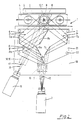
- the side wall control is performed by a on the conveyor belt 4th arranged inspection station 1, consisting essentially of a diffuse light emitting screen 2, a Camera 3 and between the conveyor belt 4 and the camera. 3 arranged mirrors for generating the beam paths 6, 7th and 8 is.
- the inspection station 1 with a second camera 15 for contour, height and / or Color detection equipped.
- Seen in the conveying direction behind the inspection station 1 is a controllable Ejector device 31 on one side of the conveyor belt 4th placed, the opposite a collecting container 32nd assigned. With the ejector device 31, e.g.
- the control of the two cameras 3, 15 and the Ejector 31 takes place under consideration of Conveying speed through one of the inspection station 1 upstream trigger light barrier 33.
- the inspection station 1 for sidewall inspection is In addition, a second inspection station 40 downstream.
- This inspection station the bottles 5 by two arranged opposite, synchronous to the conveyor belt. 4 drivable belt 41 laterally on the lateral surface trapped and ground free over several Inspection devices for ground, mouth control or Residual fluid detection to be transported. To Completion of these inspection operations will be the bottles of parked the belt 41 on a subsequent conveyor belt 45 and released.
- Behind the second inspection station 40 is again a controllable ejector device 46 with a arranged opposite to the conveyor belt 45 Tray 47 placed to pass through the first or second Inspection station 1, 40 recognized as not reusable Bottles, e.g. with outbreaks at the mouth, excrete to can. Behind it is a third ejector device 48 for discharging possibly after a new cleaning continue to use bottles on a parallel to the Conveyor belt 45 arranged arranged conveyor 49.
- the two Beam paths 6 and 7 are to the optical axis 12 of the camera 3 symmetrically formed or arranged. Accordingly are also the optical path 7 forming mirrors 7a and 7b symmetrical to the mirrors 6a and 6b of the beam path 6 positioned.
- the two mirrors 6b and 7b are so aligned with each other, that the beam paths 6 and 7 at a certain angle, e.g. 60 degrees, based on the Central axes 6 'and 7' of the beam paths, in one above the Conveyor 4 meeting intersection area 9 meet.
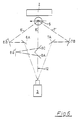
- the mirror 8c is like that positioned so that the illustrated in Fig. 2 vertical Projection of the central axis 8 'at the common Interface 10 of the three central axes 6 ', 7' and 8 'both normal to the line of symmetry 11 of the bottle to be tested 5 as is also aligned to the conveying direction of the conveyor belt 4.
- the responsible for the sidewall control Camera 3 is with equipped with a surface array on which the three Beam paths 6, 7 and 8 are shown side by side.
- the camera 3 is an evaluation device, not shown associated with the image taken by the camera evaluated programmatically.
- the evaluation program can do this be designed that of each beam path only the middle image area is evaluated while the Border areas can be hidden or ignored in order to Inaccuracies in the peripheral areas of the recorded Images due to the optical distortions to the strong to avoid curved bottle edges.
- the inspection station 1 is a second camera 15 to control the contour and / or height and / or color of assigned to bottles to be tested.
- This second camera 15 is arranged so that their beam path 16 unhindered between the mirrors of the sidewall control device through a bottle 5 located in the crossing region 9 can meet.
- the optical axis 17 of the Camera 15 aligned so that they also through the common interface 10 of the three beam paths 6, 7 and 8 of the sidewall control runs.
- This is the two Cameras 3 and 15 with a common control signal for Simultaneous image acquisition controllable. Very cheap is an arrangement of the beam path 16 of the camera 15, at the vertical projection of the optical axis 17 the vertical projection of the central axis 8 'and the optical Axis 12 of the camera 3 with an angle of about 25 degrees crosses.
- Fig. 2 In the side view of Fig. 2 shown in Fig. 3 are for the sake of clarity, only the camera 3 and the both the beam path 7 associated mirror 7a and 7b shown. Shown is the beam path of the in Fig. 2 with 7 'designated center axis.
- the positioning the plane mirrors 7a and 7b (and also the other mirrors) is done by two spaced apart parallel, respectively Positioning plates 21 lying in a horizontal plane, by spacer rods 22 on a base plate 19th are attached.
- the positioning plates 21 have the thickness and width of the mirror corresponding slots (see Fig. 2).
- the mirrors are through these slots from above insertable and stand with their lower edge on the Base plate 19. This is in the event of damage easy and quick exchange of mirrors possible.
- a guide 20th attached to the vertically arranged camera 3 is held vertically adjustable by means of a clamping piece 35.
- the clamp also has a pivot 36 for Adjustment of the angle of incidence of the optical axis 12 of the Camera 3 on the underneath on the base plate 19th arranged mirror 13.
- Fig. 5 corresponds largely to Fig. 4, wherein in addition, the camera 15 for contour and height detection with its beam path 16 is indicated. Because of the vertical Arrangement of the camera 15 is also a the beam path 16 from the vertical direction transverse to the symmetry line 11 the bottle to be tested 5 deflecting mirror 18th required.
- the second camera 15 is not in shown manner, similar to the camera 3, at the top Positioning plate 21 adjustable attached.
- Fig. 6 shows an alternative mirror arrangement for Generation of the sidewall control required Beam paths.
- the illustrated mirror assembly generates also two to the optical axis 12 of the camera. 3 symmetrically formed beam paths 6 and 7, of which only the central axes 6 'and 7' are shown.
- the with a sufficient distance to the optical axis 12 are arranged, such that the third beam path 8 forming mirror 8A, B, C before the aforementioned mirrors the two remaining beam paths can be placed, and the leading to the bottle 5 section of the beam path. 8 between the belonging to the beam paths 6 to 7 Mirroring can pass through unhindered.
- the inspection machine shown in Fig. 7 has basically the same mechanical structure as the Inspection machine according to Fig. 1. In addition, it has via an inspection station 100 for a second Sidewall inspection of the bottles 5.
- This inspection station 100 is immediately behind the belt 41 of Inspection station 40 arranged on the conveyor belt 45.
- the Mirror arrangement of the inspection station 100 agrees with the the inspection station 1 match.
- Both belts 41 are driven in synchronism with the conveyor belts 4 and 45, but with a low speed difference to each other.
- Depending on the set Speed difference will be the bottles during the Transfer from the conveyor belt 4 on the conveyor belt 45 to a certain angle, preferably about 90 degrees to their The vertical axis turned and then without rotation by itself guided the inspection station 100.
- the Excretion of unusable bottles 5 are made, as previously explained for Fig. 1 has already been explained.
- the speed difference between the two belts 41 is adjustable so that when changing the Inspection machine on bottles with another Peripheral measure of the rotation angle of the bottles when passing through the Belt length is constant 90 degrees.
- one of the two belts 41 drivingly with the conveyor belts 4 and / or 45 connected during the second belt 41 via its own, controllable drive with a programmable controller.
- the conversion of the Translation ratio between the two belts 41 can then done by pressing a button.
- a sidewall inspection with two inspection stations 1 and 100 has the advantage that the necessary intermediate distances can be kept small in the bottle stream, which also the bottle transport speed at a given Performance is lower than with a control of the whole Bottle side wall with only one inspection station. This is on the smaller angle between the rays 6 and 7 which can be chosen, e.g. 60 degrees, there the bottle sidewall when passing one of the two Inspection stations 1 and 100 are not complete must be recorded. In addition, arise by the smaller angle optical advantages in image acquisition. at a sidewall control with only a single Inspection station, however, is between the beams 6 and 7 an angle of over 100 degrees for complete detection a bottle sidewall required.
Landscapes
- General Health & Medical Sciences (AREA)
- Health & Medical Sciences (AREA)
- Chemical & Material Sciences (AREA)
- Physics & Mathematics (AREA)
- Analytical Chemistry (AREA)
- Biochemistry (AREA)
- Life Sciences & Earth Sciences (AREA)
- General Physics & Mathematics (AREA)
- Immunology (AREA)
- Pathology (AREA)
- Toxicology (AREA)
- Investigating Materials By The Use Of Optical Means Adapted For Particular Applications (AREA)
- Analysing Materials By The Use Of Radiation (AREA)
Abstract
Description
Die Erfindung betrifft eine Inspektionsmaschine für
durchleuchtbare Flaschen oder dgl. gemäß dem Oberbegriff des
Anspruchs 1.The invention relates to an inspection machine for
durchbluchtbare bottles or the like. According to the preamble of
In Getränkeabfüllinien werden derartige Inspektionsmaschinen eingesetzt, um vor dem Befüllen beschädigte oder unsaubere Flaschen zu erkennen und auszuscheiden. Zur Überprüfung des Seitenwandbereichs der Flaschen sind Inspektionssysteme bekannt, die zur Bildaufnahme der Flaschenseitenwand eine kontinuierliche Drehung der Flaschen um ihre Hochachse erfordern. Während der Drehbewegung wird von der Bildaufnahmeeinrichtung, z.B. Zeilenkamera, im wesentlichen nur die Flaschenmitte entlang einer vertikalen Linie aufgenommen. Das durch dieses Abwicklungsverfahren erhaltene Bild einer Flaschenseitenwand zeichnet sich durch eine hohe Aufnahmequalität aus, da praktisch keine optischen Verzerrungen durch die Seitenwandkrümmung auftreten. Beverage bottling lines become such inspection machines used to be damaged or dirty before filling Recognize bottles and excrete. To check the Sidewall area of the bottles are inspection systems Known for taking a picture of the bottle side wall a continuous rotation of the bottles around their vertical axis require. While the rotary motion is being used by the Image pickup device, e.g. Line scan camera, essentially only the center of the bottle along a vertical line added. The product obtained by this transaction procedure Picture of a bottle sidewall is characterized by a high Recording quality, since virtually no optical Distortions due to the sidewall curvature occur.
Andererseits erfordert die Drehung der Flaschen zur Bildaufnahme einen nicht unerheblichen mechanischen Aufwand (Karussell mit Drehtellern o.ä.).On the other hand, the rotation of the bottles requires Image recording a significant mechanical effort (Carousel with turntables or similar).
Außerdem ist bereits eine Inspektionsvorrichtung bekanntgeworden, die ohne eine Flaschendrehung während der Bildaufnahme des Seitenwandbereichs auskommt (DE-AS 26 17 457). Dabei wird der Seitenwandbereich von nur einer Kamera aus zwei verschiedenen Richtungen aufgenommen. Einerseits besitzt eine derartige Inspektionseinrichtung einen vergleichsweise einfachen Aufbau, andererseits müssen aber durch die Oberflächenkrümmung der Flasche verursachte optische Verzerrungen in den Randbereichen der aufgenommenen Bilder in Kauf genommen werden, wodurch die Bildauswertung zur Erkennung von Schmutz oder Beschädigungen erschwert wird.In addition, there is already an inspection device become known without a bottle rotation during the Image acquisition of the sidewall area manages (DE-AS 26 17 457). In this case, the side wall area of only a camera shot from two different directions. On the one hand has such an inspection device a comparatively simple structure, on the other hand but caused by the surface curvature of the bottle optical distortions in the peripheral areas of the recorded Pictures can be accepted, reducing the image analysis difficult to detect dirt or damage becomes.
Demzufolge liegt der Erfindung, aus gehend von dem zuletzt genannten Stand der Technik, die Aufgabe zugrunde, eine Inspektionsvorrichtung zur Seitenwandkontrolle von Flaschen oder dgl. anzugeben, die nur wenig Aufwand erfordert und eine gute Bildqualität liefert.Accordingly, the invention, starting from the last mentioned prior art, the object of a Inspection device for sidewall inspection of bottles or the like, which requires little effort and provides a good picture quality.
Die Aufgabe wird durch die im kennzeichnenden Teil des
Anspruchs 1 angegebenen Merkmale gelöst.The object is achieved by the in the characterizing part of
Claim specified
Besonders vorteilhaft ist eine Spiegelanordnung, die gleich lange Strahlengänge vom Seitenwandbereich einer zu prüfenden Flasche bis zur Bildaufnahmeeinrichtung (CCD-Kamera) liefert. Dadurch kann sichergestellt werden, daß die von den einzelnen Strahlengängen gelieferten Abbildungen gleich groß sind, wodurch Schwierigkeiten bei der Bildauswertung vermieden werden.Particularly advantageous is a mirror arrangement, the same long beam paths from the sidewall area of a test to be tested Bottle to the image recording device (CCD camera) supplies. This can ensure that the of the individual beam paths delivered the same size are causing difficulties in image analysis be avoided.
Eine besonders kompakte Bauweise wird durch eine in den
Ansprüchen 12 und 13 angegebene Ausgestaltung der
Inspektionseinrichtung ermöglicht.A particularly compact design is by a in the
Ferner kann der Inspektionsstation eine weitere Bildaufnahmeeinrichtung (CCD-Kamera) zur Kontrolle der Kontur, Höhe oder Farbe der die Inspektionsstation passierenden Flaschen zugeordnet werden. Diese zweite Bildaufnahmeeinrichtung kann so positioniert werden, daß ihr Strahlengang ebenfalls den Kreuzungsbereich der Strahlengänge der Seitenwandkontrolle schneidet, wodurch vorteilhafterweise durch nur eine Ansteuerung die Bildaufnahme beider Bildaufnahmeeinrichtungen gleichzeitig auslösbar ist.Furthermore, the inspection station can have another Image recording device (CCD camera) for controlling the Contour, height or color of the inspection station be assigned to passing bottles. This second Image pickup device can be positioned so that you Beam path also the crossing of the Beam path of the sidewall control cuts, causing advantageously by only one control the Image recording of both image recording devices simultaneously is triggerable.
Vorteilhafte Weiterbildungen der Inspektionsmaschine sind Gegenstand der Unteransprüche.Advantageous developments of the inspection machine are Subject of the dependent claims.
Nachfolgend werden Ausführungsbeispiele anhand der Figuren erläutert. Es zeigt:
- Fig. 1
- eine schematische Draufsicht auf eine Inspektionsmaschine mit einer Inspektionsstation zur Seitenwandkontrolle,
- Fig. 2
- eine vergrößerte Darstellung der Inspektionsstation zur Seitenwandkontrolle nach Fig. 1,
- Fig. 3
- eine erste Seitenansicht der Inspektionsstation nach Fig. 2 in Flaschenförderrichtung betrachtet,
- Fig. 4
- eine zweite Seitenansicht der Inspektionsstation nach Fig. 2 in Förderrichtung der Flaschen betrachtet,
- Fig. 5
- eine dritte Seitenansicht der Inspektionsstation nach Fig. 2 in Förderrichtung der Flaschen betrachtet,
- Fig. 6
- eine schematische Draufsicht auf eine Inspektionsstation zur Seitenwandkontrolle mit einer von der Fig. 2 abweichenden Spiegelanordnung und
- Fig. 7
- eine schematische Draufsicht auf eine Inspektionsmaschine mit zwei Inspektionsstationen zur Seitenwandkontrolle von Flaschen.
- Fig. 1
- a schematic plan view of an inspection machine with an inspection station for sidewall inspection,
- Fig. 2
- an enlarged view of the inspection station for sidewall inspection of FIG. 1,
- Fig. 3
- a first side view of the inspection station of FIG. 2 viewed in the bottle conveying direction,
- Fig. 4
- a second side view of the inspection station of FIG. 2 viewed in the conveying direction of the bottles,
- Fig. 5
- a third side view of the inspection station of FIG. 2 viewed in the conveying direction of the bottles,
- Fig. 6
- a schematic plan view of an inspection station for side wall control with a deviating from the Fig. 2 mirror assembly and
- Fig. 7
- a schematic plan view of an inspection machine with two inspection stations for sidewall control of bottles.
Wie aus der in der Fig. 1 schematisch dargestellten
Draufsicht erkennbar ist, werden die zu prüfenden Flaschen 5
durch einen kontinuierlich antreibbaren Zuförderer 14 der
Inspektionsmaschine zugeführt. Die durch den Zuförderer 14,
z.B. ein Plattenförderband, in einer geschlossenen Reihe
aufrechtstehend transportierten Flaschen 5 werden durch
Führungsgeländer 30 auf ein parallel angeordnetes, mit
erhöhter Geschwindigkeit synchron zum Zuförderer 14
angetriebenes Förderband 4 überführt, wobei durch den
Geschwindigkeitssprung Lücken bzw. Zwischenabstände im
Flaschenstrom erzeugt werden. Diese Zwischenabstände sind
zur Durchführung der Seitenwandkontrolle notwendig. As shown schematically in FIG. 1
Top view is recognizable, the bottles to be tested. 5
by a continuously driven
Die Seitenwandkontrolle erfolgt durch eine am Förderband 4
angeordnete Inspektionsstation 1, die im wesentlichen aus
einem diffuses Licht abstrahlenden Leuchtschirm 2, einer
Kamera 3 und zwischen dem Förderband 4 und der Kamera 3
angeordneten Spiegeln zur Erzeugung der Strahlengänge 6, 7
und 8 besteht. Außerdem ist die Inspektionsstation 1 mit
einer zweiten Kamera 15 zur Kontur-, Höhen- und/oder
Farberkennung ausgestattet. In Förderrichtung gesehen hinter
der Inspektionsstation 1 ist eine ansteuerbare
Auswerfereinrichtung 31 an einer Seite des Transportbandes 4
plaziert, der gegenüberliegend ein Auffangbehälter 32
zugeordnet ist. Mit der Auswerfereinrichtung 31, z.B. ein
quer zur Förderrichtung impulsartig vor- und
zurücksteuerbarer Pusher oder Stößel, können durch die
zweite Kamera 15 erkannte Fremdflaschen, die beispielsweise
einen bestimmten Durchmesser oder eine vorgebbare Höhe
überschreiten, zum Schutz nachfolgender
Inspektionseinrichtungen vom Förderband 4 entfernt werden.
Die Ansteuerung der beiden Kameras 3, 15 und der
Auswerfereinrichtung 31 erfolgt unter Berücksichtigung der
Fördergeschwindigkeit durch eine der Inspektionsstation 1
vorgeordnete Triggerlichtschranke 33.The side wall control is performed by a on the conveyor belt 4th
arranged
Der Inspektionsstation 1 zur Seitenwandkontrolle ist
außerdem eine zweite Inspektionsstation 40 nachgeordnet. In
dieser Inspektionsstation können die Flaschen 5 durch zwei
gegenüberliegend angeordnete, synchron zum Förderband 4
antreibbare Riemen 41 seitlich an der Mantelfläche
eingeklemmt und bodenfrei über mehrere
Inspektionseinrichtungen zur Boden-, Mündungskontrolle oder
Restflüssigkeitserkennung transportiert werden. Nach
Abschluß dieser Inspektionsvorgänge werden die Flaschen von
den Riemen 41 auf ein nachfolgendes Förderband 45 abgestellt
und freigegeben.The
Hinter der zweiten Inspektionsstation 40 ist wiederum eine
ansteuerbare Auswerfereinrichtung 46 mit einem
gegenüberliegend am Transportband 45 angeordneten
Auffangbehälter 47 plaziert, um durch die erste oder zweite
Inspektionsstation 1, 40 als nicht weiterverwendbar erkannte
Flaschen, z.B. mit Ausbrüchen an der Mündung, ausscheiden zu
können. Dahinterliegend ist eine dritte Auswerfereinrichtung
48 zur Ausschleusung von evtl. nach einer erneuten Reinigung
weiter verwendbaren Flaschen auf einen parallel zum
Förderband 45 angeordneten Förderer 49 vorgesehen.Behind the
Aus der Fig. 2 ist die Anordnung der die drei Strahlengänge
6, 7, 8 erzeugenden Spiegel ersichtlich. Die beiden
Strahlengänge 6 und 7 sind zur optischen Achse 12 der Kamera
3 symmetrisch ausgebildet bzw. angeordnet. Dementsprechend
sind auch die den Strahlengang 7 bildenden Spiegel 7a und 7b
symmetrisch zu den Spiegeln 6a und 6b des Strahlenganges 6
positioniert. Die beiden Spiegel 6b und 7b sind so
zueinander ausgerichtet, daß sich die Strahlengänge 6 und 7
unter einem bestimmten Winkel, z.B. 60 Grad, bezogen auf die
Mittelachsen 6' und 7' der Strahlengänge, in einem über dem
Förderband 4 liegenden Kreuzungsbereich 9 treffen. Ein
dritter Strahlengang 8 wird, ausgehend von der Kamera 3,
durch drei Spiegel 8a, 8b, 8c so umgelenkt, daß die
Mittelachse 8' dieses dritten Strahlenganges 8 im
Kreuzungsbereich 9 den von den beiden Mittelachsen 6' und 7'
eingeschlossenen Winkel halbiert. Der Spiegel 8c ist so
positioniert, daß die in Fig. 2 dargestellte senkrechte
Projektion der Mittelachse 8' an der gemeinsamen
Schnittstelle 10 der drei Mittelachsen 6', 7' und 8' sowohl
normal zur Symmetrielinie 11 der zu prüfenden Flasche 5 als
auch zur Förderrichtung des Förderbands 4 ausgerichtet ist.
Die für die Seitenwandkontrolle zuständige Kamera 3 ist mit
einem Flächenarray ausgestattet, auf dem die drei
Strahlengänge 6, 7 und 8 nebeneinander abgebildet werden.
Der Kamera 3 ist eine nicht dargestellte Auswerteinrichtung
zugeordnet, die das von der Kamera aufgenommene Bild
programmgesteuert auswertet. Das Auswertprogramm kann so
gestaltet sein, daß von jedem Strahlengang jeweils nur der
mittlere Bildbereich ausgewertet wird, während die
Randbereiche ausblendbar sind bzw. ignoriert werden, um
Ungenauigkeiten in den Randbereichen der aufgenommenen
Bilder infolge der optischen Verzerrungen an den stark
gekrümmten Flaschenrändern zu vermeiden.From Fig. 2, the arrangement of the three
Außerdem ist der Inspektionsstation 1 eine zweite Kamera 15
zur Kontrolle der Kontur- und/oder Höhe und/oder Farbe der
zu prüfenden Flaschen zugeordnet. Diese zweite Kamera 15 ist
so angeordnet, daß ihr Strahlengang 16 ungehindert zwischen
den Spiegeln der Seitenwandkontrolleinrichtung hindurch auf
eine sich gerade im Kreuzungsbereich 9 befindende Flasche 5
treffen kann. Insbesondere ist die optische Achse 17 der
Kamera 15 so ausgerichtet, daß sie ebenfalls durch die
gemeinsame Schnittstelle 10 der drei Strahlengänge 6, 7 und
8 der Seitenwandkontrolle verläuft. Dadurch sind die beiden
Kameras 3 und 15 mit einem gemeinsamen Steuersignal zur
gleichzeitigen Bildaufnahme ansteuerbar. Besonders günstig
ist eine Anordnung des Strahlengangs 16 der Kamera 15, bei
der die senkrechte Projektion der optischen Achse 17 die
senkrechte Projektion der Mittelachse 8' bzw. die optische
Achse 12 der Kamera 3 mit einem Winkel von ca. 25 Grad
kreuzt.In addition, the
Abweichend von der Darstellung in Fig. 2 können die beiden
Kameras 3 und 15 mit ihren optischen Achsen 12 und 17
senkrecht zur Förderebene der Flaschen stehend angeordnet
werden. Diese Alternative ist in der Fig. 2 mit
gestrichelten Umrißlinien angedeutet und in den Fig. 3 bis 5
dargestellt.Deviating from the illustration in Fig. 2, the two
Diese Anordnung gestattet eine sehr kompakte, platzsparende
Bauweise der Inspektionsstation 1, da der quer zum
Förderband 4 erforderliche Abstand im Vergleich zur
Ausführung nach Fig. 2 deutlich verkürzt werden kann.This arrangement allows a very compact, space-saving
Construction of the
In der in Fig. 3 dargestellten Seitenansicht der Fig. 2 sind
zwecks der besseren Übersicht nur die Kamera 3 und die
beiden dem Strahlengang 7 zugeordneten Spiegel 7a und 7b
dargestellt. Eingezeichnet ist der Strahlverlauf der in
Fig. 2 mit 7' bezeichneten Mittelachse. Die Positionierung
der ebenen Spiegel 7a und 7b (und auch der übrigen Spiegel)
erfolgt durch zwei mit Abstand zueinander parallel, jeweils
in einer horizontalen Ebene liegende Positionierplatten 21,
die durch Distanzstangen 22 auf einer Grundplatte 19
befestigt sind. Die Positionierplatten 21 besitzen der Dicke
und Breite der Spiegel entsprechende Schlitze (siehe
Fig. 2). Die Spiegel sind durch diese Schlitze von oben her
einführbar und stehen mit ihrer unteren Kante auf der
Grundplatte 19. Dadurch ist im Falle von Beschädigungen ein
einfacher und schneller Austausch der Spiegel möglich.In the side view of Fig. 2 shown in Fig. 3 are
for the sake of clarity, only the
Auf der oberen Positionierplatte 21 ist eine Führung 20
befestigt, an der die senkrecht stehend angeordnete Kamera 3
mittels einem Klemmstück 35 höhenverstellbar gehalten wird.
Das Klemmstück besitzt außerdem ein Drehgelenk 36 zur
Einstellung des Auftreffwinkels der optischen Achse 12 der
Kamera 3 auf den darunter auf der Grundplatte 19
angeordneten Spiegel 13.On the
In Fig. 4 sind die dem mittleren Strahlengang 8 zugeordneten
Spiegel 8a, 8b und 8c dargestellt, wobei ebenfalls zur
besseren Übersicht alle übrigen Spiegel nicht eingezeichnet
sind.In Fig. 4 which are associated with the
Die Fig. 5 entspricht weitgehend der Fig. 4, wobei
zusätzlich die Kamera 15 zur Kontur- und Höhenerkennung mit
ihrem Strahlengang 16 angedeutet ist. Wegen der senkrechten
Anordnung der Kamera 15 ist ebenfalls ein den Strahlengang
16 aus der senkrechten Richtung quer zur Symmetrielinie 11
der zu prüfenden Flasche 5 umlenkender Spiegel 18
erforderlich. Die zweite Kamera 15 ist in nicht
dargestellter Weise, ähnlich wie die Kamera 3, an der oberen
Positionierplatte 21 einstellbar befestigt.Fig. 5 corresponds largely to Fig. 4, wherein
in addition, the
Zur Kontur- und Höhenkontrolle reicht die Erfassung des
Schulter- und Kopfbereiches der Flaschen 5. Dadurch genügt
im Vergleich zu den Strahlengängen der Seitenwandkontrolle
eine kürzere Länge des Strahlengangs 17, so daß die Kamera
15 ohne zusätzliche Umlenkspiegel ähnlich nahe an der
Flasche 5 angeordnet werden kann, wie die zur
Seitenwandkontrolle dienende Kamera 3.For contour and height control, the detection of the
Shoulder and head area of the
Die Fig. 6 zeigt eine alternative Spiegelanordnung zur
Erzeugung der zur Seitenwandkontrolle erforderlichen
Strahlengänge. Die dargestellte Spiegelanordnung erzeugt
ebenfalls zwei zur optischen Achse 12 der Kamera 3
symmetrisch ausgebildete Strahlengänge 6 und 7, von denen
nur die Mittelachsen 6'und 7' dargestellt sind. Zu diesem
Zweck sind jeweils Spiegel 6A, 6B und 7A, 7B vorhanden, die
mit einem ausreichenden Zwischenabstand zur optischen Achse
12 angeordnet sind, derart, daß die den dritten Strahlengang
8 bildenden Spiegel 8A, B, C vor den vorgenannten Spiegeln
der beiden übrigen Strahlengänge plaziert werden können, und
der zur Flasche 5 führende Abschnitt des Strahlengangs 8
zwischen den zu den Strahlengängen 6 bis 7 gehörenden
Spiegeln ungehindert hindurchtreten kann.Fig. 6 shows an alternative mirror arrangement for
Generation of the sidewall control required
Beam paths. The illustrated mirror assembly generates
also two to the
Abweichend von den dargestellten Ausführungen sind auch Spiegelanordnungen denkbar und vorteilhaft, die zur Seitenwandkontrolle mehr als drei Strahlengänge erzeugen.Deviating from the illustrated embodiments are also Mirror arrangements conceivable and advantageous, the Sidewall control generate more than three optical paths.
Die in Fig. 7 dargestellte Inspektionsmaschine besitzt
grundsätzlich den gleichen mechanischen Aufbau wie die
Inspektionsmaschine nach Fig. 1. Zusätzlich verfügt sie aber
über eine Inspektionsstation 100 für eine zweite
Seitenwandkontrolle der Flaschen 5. Diese Inspektionsstation
100 ist unmittelbar hinter den Riemen 41 der
Inspektionsstation 40 am Förderband 45 angeordnet. Die
Spiegelanordnung der Inspektionsstation 100 stimmt mit der
der Inspektionsstation 1 überein. Beide Riemen 41 werden
synchron zu den Förderbändern 4 und 45 angetrieben,
allerdings mit einer geringen Geschwindigkeitsdifferenz
zueinander. In Abhängigkeit der eingestellten
Geschwindigkeitsdifferenz werden die Flaschen während der
Überführung vom Förderband 4 auf das Förderband 45 um einen
bestimmten Winkel, vorzugsweise ca. 90 Grad, um ihre
Hochachse gedreht und anschließend ohne Eigendrehung durch
die Inspektionsstation 100 geführt. Nachfolgend kann die
Ausscheidung unbrauchbarer Flaschen 5 vorgenommen werden,
wie vorhergehend zur Fig. 1 bereits erläutert wurde.The inspection machine shown in Fig. 7 has
basically the same mechanical structure as the
Inspection machine according to Fig. 1. In addition, it has
via an
Die Geschwindigkeitsdifferenz zwischen den beiden Riemen 41
ist so einstellbar, daß bei einer Umstellung der
Inspektionsmaschine auf Flaschen mit einem anderen
Umfangsmaß der Drehwinkel der Flaschen beim Durchfahren der
Riemenstrecke konstant 90 Grad beträgt. Zu diesem Zweck ist
beispielsweise einer der beiden Riemen 41 antriebsmäßig mit
den Förderbändern 4 und/oder 45 verbunden, während der
zweite Riemen 41 über einen eigenen, regelbaren Antrieb mit
einer programmierbaren Steuerung verfügt. Die Umstellung des
Übersetzungsverhältnisses zwischen den beiden Riemen 41 kann
dann auf Knopfdruck erfolgen.The speed difference between the two
Eine Seitenwandkontrolle mit zwei Inspektionsstationen 1 und
100 hat den Vorteil, daß die erforderlichen Zwischenabstände
im Flaschenstrom klein gehalten werden können, wodurch auch
die Flaschentransportgeschwindigkeit bei einer vorgegebenen
Leistung niedriger ist, als bei einer Kontrolle der gesamten
Flaschenseitenwand mit nur einer Inspektionsstation. Dies
ist auf den kleineren Winkel zwischen den Strahlen 6 und 7
zurückzuführen, der gewählt werden kann, z.B. 60 Grad, da
die Flaschenseitenwand beim Passieren einer der beiden
Inspektionsstationen 1 und 100 nicht vollumfänglich
aufgenommen werden muß. Zusätzlich ergeben sich durch den
kleineren Winkel optische Vorteile bei der Bildaufnahme. Bei
einer Seitenwandkontrolle mit nur einer einzigen
Inspektionsstation ist dagegen zwischen den Strahlen 6 und 7
ein Winkel von über 100 Grad zur vollständigen Erfassung
einer Flaschenseitenwand erforderlich.A sidewall inspection with two
Claims (25)
Applications Claiming Priority (5)
| Application Number | Priority Date | Filing Date | Title |
|---|---|---|---|
| DE9311405U | 1993-07-30 | ||
| DE19939311405 DE9311405U1 (en) | 1993-07-30 | 1993-07-30 | Inspection machine |
| DE9313115U | 1993-09-01 | ||
| DE19939313115 DE9313115U1 (en) | 1993-09-01 | 1993-09-01 | Inspection machine |
| EP94924822A EP0663069B1 (en) | 1993-07-30 | 1994-07-29 | Inspection machine |
Related Parent Applications (2)
| Application Number | Title | Priority Date | Filing Date |
|---|---|---|---|
| EP94924822A Division EP0663069B1 (en) | 1993-07-30 | 1994-07-29 | Inspection machine |
| EP94924822.3 Division | 1995-02-09 |
Publications (3)
| Publication Number | Publication Date |
|---|---|
| EP1553405A2 true EP1553405A2 (en) | 2005-07-13 |
| EP1553405A3 EP1553405A3 (en) | 2005-09-07 |
| EP1553405B1 EP1553405B1 (en) | 2011-03-30 |
Family
ID=25961073
Family Applications (3)
| Application Number | Title | Priority Date | Filing Date |
|---|---|---|---|
| EP05005396A Expired - Lifetime EP1553405B1 (en) | 1993-07-30 | 1994-07-29 | Inspecting machine |
| EP01112238A Expired - Lifetime EP1130384B1 (en) | 1993-07-30 | 1994-07-29 | Inspecting machine |
| EP94924822A Expired - Lifetime EP0663069B1 (en) | 1993-07-30 | 1994-07-29 | Inspection machine |
Family Applications After (2)
| Application Number | Title | Priority Date | Filing Date |
|---|---|---|---|
| EP01112238A Expired - Lifetime EP1130384B1 (en) | 1993-07-30 | 1994-07-29 | Inspecting machine |
| EP94924822A Expired - Lifetime EP0663069B1 (en) | 1993-07-30 | 1994-07-29 | Inspection machine |
Country Status (7)
| Country | Link |
|---|---|
| US (1) | US5729340A (en) |
| EP (3) | EP1553405B1 (en) |
| JP (1) | JP3604388B2 (en) |
| KR (1) | KR950703733A (en) |
| BR (1) | BR9405536A (en) |
| DE (3) | DE59410287D1 (en) |
| WO (1) | WO1995004267A1 (en) |
Cited By (1)
| Publication number | Priority date | Publication date | Assignee | Title |
|---|---|---|---|---|
| WO2021219959A1 (en) * | 2020-04-30 | 2021-11-04 | Tiama | Apparatus and method for simultaneously focusing optical systems according to the diameter of the containers |
Families Citing this family (55)
| Publication number | Priority date | Publication date | Assignee | Title |
|---|---|---|---|---|
| GB9416406D0 (en) * | 1994-08-13 | 1994-10-05 | Univ Of Huddersfield | Colour inspection system |
| AU9315498A (en) * | 1997-10-10 | 1999-05-03 | Northeast Robotics Llc | Imaging method and system with elongate inspection zone |
| US5895911A (en) * | 1998-01-22 | 1999-04-20 | Emhart Glass S.A. | Glass container body check detector |
| AU742980B2 (en) * | 1999-10-13 | 2002-01-17 | Kawasaki Jukogyo Kabushiki Kaisha | Random work arranging device |
| DE10027226C1 (en) * | 2000-05-31 | 2001-10-18 | Krones Ag | Transparent drinks bottle inspection method has single camera used to provide 2 images evaluated separately with variation of exposure timing between images |
| DE10164058B4 (en) * | 2000-12-30 | 2008-06-12 | Krones Ag | inspection device |
| KR20010079284A (en) * | 2001-07-02 | 2001-08-22 | 서용교 | Desired Grain Sorting out of Miscellaneous Grain Crop by color reflected from the Mirror |
| KR20030011175A (en) * | 2001-07-28 | 2003-02-07 | 삼성전자주식회사 | Soldering inspection apparatus |
| KR20030046616A (en) * | 2001-12-06 | 2003-06-18 | 삼성전자주식회사 | Micro-bubble analyzing apparatus for high-purity glass tube using laser light scattering |
| DE10339473A1 (en) * | 2003-08-27 | 2005-03-24 | Seidenader Maschinenbau Gmbh | Device for testing products |
| DE102004013774B4 (en) | 2004-03-20 | 2018-10-04 | Khs Gmbh | Inspection device for containers made of glass or a translucent material |
| FR2873206B1 (en) | 2004-07-13 | 2007-11-23 | Iris Inspection Machines Sa | MACHINE FOR DETECTING DEFECTS OF A TRANSPARENT OR TRANSLUCENT OBJECT |
| DE102005017957A1 (en) * | 2005-04-18 | 2006-10-26 | Khs Ag | inspection device |
| DE102005023534B4 (en) * | 2005-05-21 | 2007-04-12 | Krones Ag | Device for inspecting labeled vessels |
| DE102005036796A1 (en) * | 2005-08-02 | 2007-02-08 | Krones Ag | Apparatus and method for detecting bottle characteristics |
| DE202005020478U1 (en) * | 2005-12-30 | 2007-05-24 | Krones Ag | Device for inspecting labels on containers |
| JP4809168B2 (en) * | 2006-09-19 | 2011-11-09 | アサヒ飲料株式会社 | Bottle container inspection device |
| US7626158B2 (en) * | 2006-10-23 | 2009-12-01 | Emhart Glass S.A. | Machine for inspecting glass containers |
| DE102007020460B3 (en) * | 2007-04-27 | 2009-01-08 | Krones Ag | Inspection device and inspection method for containers |
| DE102007025524B4 (en) * | 2007-05-31 | 2010-07-29 | Khs Ag | Opto-electrical detection system |
| DE102007036621A1 (en) | 2007-07-31 | 2009-02-05 | Miho Inspektionssysteme Gmbh | Bottle e.g. beverage bottle, testing method for use in beverage industry, involves analyzing bottle image by image sensor and image processing system, and using self-luminous image for detecting preselected characteristics of bottle |
| JP5298327B2 (en) * | 2008-08-26 | 2013-09-25 | キリンテクノシステム株式会社 | Foreign matter inspection apparatus and foreign matter inspection system |
| DE102008063076B3 (en) * | 2008-12-24 | 2010-04-29 | Krones Ag | Bottle inspection device with image-corrected mirror cabinet |
| DE102009020919A1 (en) * | 2009-05-12 | 2010-11-18 | Krones Ag | Device for detecting elevations and / or depressions on bottles, in particular in a labeling machine |
| DE102010004972A1 (en) * | 2010-01-18 | 2011-07-21 | Krones Ag, 93073 | Object i.e. glass bottle, inspecting method for filling and packing system, involves outputting data sets by inspection devices, where data sets characterize inspected areas of object and are associated with each other |
| GB2482473A (en) * | 2010-06-29 | 2012-02-08 | Constar Internat Uk Ltd | Inspection of articles |
| US20130278927A1 (en) * | 2010-11-01 | 2013-10-24 | Make-All Corporation | Raised Vial Stopper Detection System |
| DE102011004584A1 (en) * | 2011-02-23 | 2012-08-23 | Krones Aktiengesellschaft | Method and apparatus for detecting bubbles and / or wrinkles on labeled containers |
| AT510849B1 (en) * | 2011-06-28 | 2012-07-15 | Medek & Schoerner Gmbh | DEVICE FOR THE OPTICAL RECORDING OF OBJECTS |
| DE102011083037A1 (en) | 2011-09-20 | 2013-03-21 | Krones Aktiengesellschaft | Method and device for inspection of containers and preforms |
| DE102012009783B3 (en) * | 2012-05-18 | 2013-08-14 | Khs Gmbh | Method and device for inspection of empty bottles |
| US20150246750A1 (en) * | 2012-10-04 | 2015-09-03 | Fuji Seal International, Inc. | Container with shrink-fit label, shrink-fit label, and manufacturing method for container with shrink-fit label |
| DE102014102450A1 (en) * | 2014-02-25 | 2015-08-27 | Khs Gmbh | Inspection device with inverse foil lens |
| DE102014104078B4 (en) | 2014-03-25 | 2019-04-25 | Krones Ag | Inspection device and inspection method for the transmitted light inspection of containers |
| DE102014106380A1 (en) | 2014-05-07 | 2015-11-12 | Krones Ag | Method and device for transporting containers |
| DE102014216188A1 (en) * | 2014-08-14 | 2016-02-18 | Krones Ag | Optical inspection method and optical inspection device for containers |
| DE102015204412A1 (en) | 2015-03-11 | 2016-09-15 | Krones Ag | Inspection device for inspecting bottles |
| DE102015218356A1 (en) | 2015-09-24 | 2017-03-30 | Krones Ag | Inspection method and apparatus for optical transmitted light inspection of unlabeled containers |
| US20170244904A1 (en) * | 2016-02-18 | 2017-08-24 | The Boeing Company | Optical monitoring system and method for imaging a component under test |
| EP3208782B1 (en) | 2016-02-22 | 2022-10-19 | Wincor Nixdorf International GmbH | Empties returning device |
| WO2017204766A2 (en) | 2016-05-26 | 2017-11-30 | Turkiye Sise Ve Cam Fabrikalari A. S. | A quality control system for semi-finished glass products |
| WO2017204765A2 (en) | 2016-05-26 | 2017-11-30 | Turkiye Sise Ve Cam Fabrikalari A. S. | A quality control system for household glass products |
| FR3056296B1 (en) * | 2016-09-19 | 2018-10-19 | Tiama | INSTALLATION FOR THE OPTICAL INSPECTION OF GLASS CONTAINERS OUTPUT OF FORMING MACHINE |
| DE102017201776B4 (en) * | 2017-02-03 | 2023-03-09 | Krones Ag | Inspection apparatus and method for sidewall and closure head inspection of containers |
| DE102017206971A1 (en) | 2017-04-26 | 2018-10-31 | Krones Aktiengesellschaft | Inspection method and apparatus for image inspection of containers |
| UY38287A (en) | 2018-07-30 | 2019-08-30 | Grifols Worldwide Operations Ltd | PROCEDURE AND DEVICE TO DETECT DEFECTS IN THE CLOSURE OF ENCAPSULATED VIALS |
| EP3715835B1 (en) | 2019-03-29 | 2024-11-06 | Pharmacontrol Electronic GmbH | Inspection system |
| CN110006598B (en) * | 2019-04-24 | 2024-03-12 | 山东省科学院海洋仪器仪表研究所 | Penicillin bottle online leakage detection device and method |
| US11047803B1 (en) * | 2020-09-10 | 2021-06-29 | Applied Vision Corporation | Glass container inspection system |
| JP2023550484A (en) * | 2020-11-24 | 2023-12-01 | コスカ ファミリー リミテッド | System and method for testing blow fill seal (BFS) products |
| DE102021115493A1 (en) * | 2021-06-15 | 2022-12-15 | Heuft Systemtechnik Gmbh | Process and device for full container inspection |
| DE102021115729A1 (en) * | 2021-06-17 | 2022-12-22 | Krones Aktiengesellschaft | Device and method for inspecting filled containers and their contents |
| IT202200001496A1 (en) * | 2022-01-28 | 2023-07-28 | Marco Lottici | APPARATUS AND METHOD FOR THE INSPECTION OF CONTAINERS, IN PARTICULAR GLASS BOTTLES WITH THREADED NECKS |
| CN120091960A (en) * | 2022-08-22 | 2025-06-03 | 工业动力有限公司 | Hybrid star wheel system for checking empty bottles |
| CN119124035A (en) * | 2024-10-30 | 2024-12-13 | 广东艾特易仪器设备有限公司 | A system and method for measuring the outer contour and bottle mouth size of an empty PET bottle or an empty glass bottle |
Family Cites Families (17)
| Publication number | Priority date | Publication date | Assignee | Title |
|---|---|---|---|---|
| GB977059A (en) * | 1960-01-28 | 1964-12-02 | Emi Ltd | Improvements relating to optical inspection apparatus |
| US3932042A (en) * | 1974-05-20 | 1976-01-13 | Barry-Wehmiller Company | Container inspection apparatus and method of inspection |
| US4025201A (en) * | 1975-04-21 | 1977-05-24 | Ball Brothers Service Corporation | Method and apparatus for video inspection of articles of manufacture by decussate paths of light |
| GB1600400A (en) * | 1977-10-13 | 1981-10-14 | Ti Fords Ltd | Bottle inspection apparatus |
| JPS5546172A (en) * | 1978-09-29 | 1980-03-31 | Kirin Brewery Co Ltd | Detector for foreign material |
| ES8205060A1 (en) * | 1980-03-28 | 1982-05-16 | Udaras Na Gaeltachta | Apparatus for the inspection of translucent containers. |
| DE3035077A1 (en) * | 1980-09-17 | 1982-04-22 | Siemens AG, 1000 Berlin und 8000 München | Optical bottle inspection appts. - has symmetrical arrangement of mirrors behind bottle reflecting light into TV camera |
| US4553217A (en) * | 1981-07-08 | 1985-11-12 | Ball Corporation | Glassware gauging system |
| US4500203A (en) * | 1982-09-30 | 1985-02-19 | Owens-Illinois, Inc. | Method and apparatus for inspecting articles |
| US4509081A (en) * | 1982-11-29 | 1985-04-02 | Industrial Automation Corp. | Optical system for automatic sorting and inspection equipment |
| US4586080A (en) * | 1984-03-22 | 1986-04-29 | Ball Corporation | Method and apparatus for video inspection of articles of manufacture |
| US4691231A (en) * | 1985-10-01 | 1987-09-01 | Vistech Corporation | Bottle inspection system |
| JPH0799326B2 (en) * | 1986-08-30 | 1995-10-25 | 株式会社マキ製作所 | Appearance inspection method and apparatus for spherical articles |
| US4751386A (en) * | 1987-03-31 | 1988-06-14 | Emhart Industries, Inc. | Lean detector for determining the offset of an axis of symmetry of a container from its norm |
| US4958223A (en) * | 1988-09-16 | 1990-09-18 | Owens-Brockway Glass Container Inc. | Inspection of container finish |
| JP2944092B2 (en) * | 1989-01-27 | 1999-08-30 | 株式会社マキ製作所 | Appearance inspection equipment for goods |
| US5256871A (en) * | 1992-12-22 | 1993-10-26 | Emhart Glass Machinery Investments Inc. | Machine for video inspection of glass containers with intersecting light beams |
-
1994
- 1994-07-29 DE DE59410287T patent/DE59410287D1/en not_active Expired - Lifetime
- 1994-07-29 US US08/406,911 patent/US5729340A/en not_active Expired - Lifetime
- 1994-07-29 BR BR9405536-0A patent/BR9405536A/en not_active Application Discontinuation
- 1994-07-29 EP EP05005396A patent/EP1553405B1/en not_active Expired - Lifetime
- 1994-07-29 KR KR1019950700954A patent/KR950703733A/en not_active Withdrawn
- 1994-07-29 EP EP01112238A patent/EP1130384B1/en not_active Expired - Lifetime
- 1994-07-29 WO PCT/EP1994/002523 patent/WO1995004267A1/en not_active Ceased
- 1994-07-29 JP JP50557295A patent/JP3604388B2/en not_active Expired - Lifetime
- 1994-07-29 EP EP94924822A patent/EP0663069B1/en not_active Expired - Lifetime
- 1994-07-29 DE DE59410415T patent/DE59410415D1/en not_active Expired - Lifetime
- 1994-07-29 DE DE59410463T patent/DE59410463D1/en not_active Expired - Lifetime
Non-Patent Citations (1)
| Title |
|---|
| None |
Cited By (3)
| Publication number | Priority date | Publication date | Assignee | Title |
|---|---|---|---|---|
| WO2021219959A1 (en) * | 2020-04-30 | 2021-11-04 | Tiama | Apparatus and method for simultaneously focusing optical systems according to the diameter of the containers |
| FR3109820A1 (en) * | 2020-04-30 | 2021-11-05 | Tiama | Installation and method for ensuring the simultaneous development of optical systems as a function of the diameter of the containers |
| US12092586B2 (en) | 2020-04-30 | 2024-09-17 | Tiama | Apparatus and method for simultaneously focusing optical systems according to the diameter of the containers |
Also Published As
| Publication number | Publication date |
|---|---|
| EP1553405B1 (en) | 2011-03-30 |
| DE59410415D1 (en) | 2005-12-08 |
| EP1130384A8 (en) | 2001-12-05 |
| BR9405536A (en) | 1999-09-08 |
| US5729340A (en) | 1998-03-17 |
| DE59410463D1 (en) | 2011-05-12 |
| WO1995004267A1 (en) | 1995-02-09 |
| JPH08505947A (en) | 1996-06-25 |
| EP0663069A1 (en) | 1995-07-19 |
| KR950703733A (en) | 1995-09-20 |
| JP3604388B2 (en) | 2004-12-22 |
| EP1130384B1 (en) | 2003-05-14 |
| EP0663069B1 (en) | 2005-11-02 |
| EP1553405A3 (en) | 2005-09-07 |
| DE59410287D1 (en) | 2003-06-18 |
| EP1130384A1 (en) | 2001-09-05 |
Similar Documents
| Publication | Publication Date | Title |
|---|---|---|
| EP0663069B1 (en) | Inspection machine | |
| EP0415154B2 (en) | Method for inspecting objects from different viewing angles | |
| EP0338376B1 (en) | Method for reading optical markings on objects and device for its implementation | |
| EP0433666B1 (en) | Three-dimensional inspection apparatus for hollow bodies | |
| DE4417015A1 (en) | Sorting machine for sorting or classifying small products of the pharmaceutical and confectionery industries by shape and color | |
| DE2256736B2 (en) | Measuring arrangement for the automatic testing of the surface quality and evenness of a workpiece surface | |
| EP0836093A2 (en) | Method and apparatus for optical weld inspection | |
| WO2013045131A1 (en) | Device and method for aligning containers | |
| EP0847187B1 (en) | Scanning apparatus for picture-element-wise photoelectric measurement of a measured object | |
| DE2617457A1 (en) | METHOD OF GENERATING A VISUAL IMAGE OF AN OBJECTIVE TO BE TESTED BY MEANS OF TRANSMISSION AND OPTICAL TESTING DEVICE | |
| DE2338295C2 (en) | Apparatus for detecting defects on opposing surfaces of a substantially flat path | |
| EP1606579B1 (en) | Lateral surface sensor and imaging lens system therefor | |
| DE9313115U1 (en) | Inspection machine | |
| EP0708325B1 (en) | Method and device for the inspection of objects, especially bottles | |
| EP0349823A1 (en) | Method and apparatus for testing cigarettes | |
| DE2903529A1 (en) | METHOD FOR MEASURING DISTANCES AND DEVICE FOR CARRYING OUT THE METHOD | |
| DE2707544A1 (en) | COAERENT SCANNING DEVICE FOR INSPECTING TEXTILE MATERIAL | |
| DE9311405U1 (en) | Inspection machine | |
| EP0270062B1 (en) | Image pick-up device | |
| DE29919761U1 (en) | Inspection machine | |
| DE29502708U1 (en) | Inspection device | |
| DE4401020A1 (en) | Method for checking profile dimensions of elongate products | |
| DE29606592U1 (en) | Inspection machine for x-ray bottles or the like. | |
| EP0386154B1 (en) | Device for inspecting webs of material travelling at high speed | |
| DE69522081T2 (en) | Device for quality and continuity control of a strip applied to a surface |
Legal Events
| Date | Code | Title | Description |
|---|---|---|---|
| PUAI | Public reference made under article 153(3) epc to a published international application that has entered the european phase |
Free format text: ORIGINAL CODE: 0009012 |
|
| 17P | Request for examination filed |
Effective date: 20050311 |
|
| AC | Divisional application: reference to earlier application |
Ref document number: 0663069 Country of ref document: EP Kind code of ref document: P |
|
| AK | Designated contracting states |
Kind code of ref document: A2 Designated state(s): DE FR GB IT |
|
| PUAL | Search report despatched |
Free format text: ORIGINAL CODE: 0009013 |
|
| AK | Designated contracting states |
Kind code of ref document: A3 Designated state(s): DE FR GB IT |
|
| RIC1 | Information provided on ipc code assigned before grant |
Ipc: 7B 07C 5/34 B Ipc: 7G 01N 21/90 A Ipc: 7B 07C 5/12 B Ipc: 7G 01B 11/16 B |
|
| AKX | Designation fees paid |
Designated state(s): DE FR GB IT |
|
| APBN | Date of receipt of notice of appeal recorded |
Free format text: ORIGINAL CODE: EPIDOSNNOA2E |
|
| APBR | Date of receipt of statement of grounds of appeal recorded |
Free format text: ORIGINAL CODE: EPIDOSNNOA3E |
|
| APAF | Appeal reference modified |
Free format text: ORIGINAL CODE: EPIDOSCREFNE |
|
| APBT | Appeal procedure closed |
Free format text: ORIGINAL CODE: EPIDOSNNOA9E |
|
| GRAC | Information related to communication of intention to grant a patent modified |
Free format text: ORIGINAL CODE: EPIDOSCIGR1 |
|
| GRAP | Despatch of communication of intention to grant a patent |
Free format text: ORIGINAL CODE: EPIDOSNIGR1 |
|
| GRAS | Grant fee paid |
Free format text: ORIGINAL CODE: EPIDOSNIGR3 |
|
| GRAA | (expected) grant |
Free format text: ORIGINAL CODE: 0009210 |
|
| AC | Divisional application: reference to earlier application |
Ref document number: 0663069 Country of ref document: EP Kind code of ref document: P |
|
| AK | Designated contracting states |
Kind code of ref document: B1 Designated state(s): DE FR GB IT |
|
| REG | Reference to a national code |
Ref country code: GB Ref legal event code: FG4D Free format text: NOT ENGLISH |
|
| REF | Corresponds to: |
Ref document number: 59410463 Country of ref document: DE Date of ref document: 20110512 Kind code of ref document: P |
|
| REG | Reference to a national code |
Ref country code: DE Ref legal event code: R096 Ref document number: 59410463 Country of ref document: DE Effective date: 20110512 |
|
| PLBI | Opposition filed |
Free format text: ORIGINAL CODE: 0009260 |
|
| PLAX | Notice of opposition and request to file observation + time limit sent |
Free format text: ORIGINAL CODE: EPIDOSNOBS2 |
|
| 26 | Opposition filed |
Opponent name: EGLI, RICHARD A. Effective date: 20111230 |
|
| REG | Reference to a national code |
Ref country code: DE Ref legal event code: R026 Ref document number: 59410463 Country of ref document: DE Effective date: 20111230 |
|
| PLAF | Information modified related to communication of a notice of opposition and request to file observations + time limit |
Free format text: ORIGINAL CODE: EPIDOSCOBS2 |
|
| PLBB | Reply of patent proprietor to notice(s) of opposition received |
Free format text: ORIGINAL CODE: EPIDOSNOBS3 |
|
| PLBD | Termination of opposition procedure: decision despatched |
Free format text: ORIGINAL CODE: EPIDOSNOPC1 |
|
| PLBP | Opposition withdrawn |
Free format text: ORIGINAL CODE: 0009264 |
|
| PLBM | Termination of opposition procedure: date of legal effect published |
Free format text: ORIGINAL CODE: 0009276 |
|
| STAA | Information on the status of an ep patent application or granted ep patent |
Free format text: STATUS: OPPOSITION PROCEDURE CLOSED |
|
| 27C | Opposition proceedings terminated |
Effective date: 20130502 |
|
| PGFP | Annual fee paid to national office [announced via postgrant information from national office to epo] |
Ref country code: DE Payment date: 20130724 Year of fee payment: 20 |
|
| PGFP | Annual fee paid to national office [announced via postgrant information from national office to epo] |
Ref country code: GB Payment date: 20130724 Year of fee payment: 20 Ref country code: FR Payment date: 20130724 Year of fee payment: 20 |
|
| PGFP | Annual fee paid to national office [announced via postgrant information from national office to epo] |
Ref country code: IT Payment date: 20130717 Year of fee payment: 20 |
|
| REG | Reference to a national code |
Ref country code: DE Ref legal event code: R071 Ref document number: 59410463 Country of ref document: DE |
|
| REG | Reference to a national code |
Ref country code: DE Ref legal event code: R071 Ref document number: 59410463 Country of ref document: DE |
|
| REG | Reference to a national code |
Ref country code: GB Ref legal event code: PE20 Expiry date: 20140728 |
|
| PG25 | Lapsed in a contracting state [announced via postgrant information from national office to epo] |
Ref country code: DE Free format text: LAPSE BECAUSE OF EXPIRATION OF PROTECTION Effective date: 20140730 |
|
| PG25 | Lapsed in a contracting state [announced via postgrant information from national office to epo] |
Ref country code: GB Free format text: LAPSE BECAUSE OF EXPIRATION OF PROTECTION Effective date: 20140728 |