EP1130384B1 - Inspecting machine - Google Patents
Inspecting machine Download PDFInfo
- Publication number
- EP1130384B1 EP1130384B1 EP01112238A EP01112238A EP1130384B1 EP 1130384 B1 EP1130384 B1 EP 1130384B1 EP 01112238 A EP01112238 A EP 01112238A EP 01112238 A EP01112238 A EP 01112238A EP 1130384 B1 EP1130384 B1 EP 1130384B1
- Authority
- EP
- European Patent Office
- Prior art keywords
- bottles
- machine according
- image recording
- inspection machine
- lightbeams
- Prior art date
- Legal status (The legal status is an assumption and is not a legal conclusion. Google has not performed a legal analysis and makes no representation as to the accuracy of the status listed.)
- Expired - Lifetime
Links
- 0 C*1CCCC1 Chemical compound C*1CCCC1 0.000 description 1
Images


Classifications
-
- B—PERFORMING OPERATIONS; TRANSPORTING
- B07—SEPARATING SOLIDS FROM SOLIDS; SORTING
- B07C—POSTAL SORTING; SORTING INDIVIDUAL ARTICLES, OR BULK MATERIAL FIT TO BE SORTED PIECE-MEAL, e.g. BY PICKING
- B07C5/00—Sorting according to a characteristic or feature of the articles or material being sorted, e.g. by control effected by devices which detect or measure such characteristic or feature; Sorting by manually actuated devices, e.g. switches
- B07C5/04—Sorting according to size
- B07C5/12—Sorting according to size characterised by the application to particular articles, not otherwise provided for
- B07C5/122—Sorting according to size characterised by the application to particular articles, not otherwise provided for for bottles, ampoules, jars and other glassware
-
- G—PHYSICS
- G01—MEASURING; TESTING
- G01N—INVESTIGATING OR ANALYSING MATERIALS BY DETERMINING THEIR CHEMICAL OR PHYSICAL PROPERTIES
- G01N21/00—Investigating or analysing materials by the use of optical means, i.e. using sub-millimetre waves, infrared, visible or ultraviolet light
- G01N21/84—Systems specially adapted for particular applications
- G01N21/88—Investigating the presence of flaws or contamination
- G01N21/90—Investigating the presence of flaws or contamination in a container or its contents
-
- B—PERFORMING OPERATIONS; TRANSPORTING
- B07—SEPARATING SOLIDS FROM SOLIDS; SORTING
- B07C—POSTAL SORTING; SORTING INDIVIDUAL ARTICLES, OR BULK MATERIAL FIT TO BE SORTED PIECE-MEAL, e.g. BY PICKING
- B07C5/00—Sorting according to a characteristic or feature of the articles or material being sorted, e.g. by control effected by devices which detect or measure such characteristic or feature; Sorting by manually actuated devices, e.g. switches
- B07C5/04—Sorting according to size
- B07C5/12—Sorting according to size characterised by the application to particular articles, not otherwise provided for
- B07C5/122—Sorting according to size characterised by the application to particular articles, not otherwise provided for for bottles, ampoules, jars and other glassware
- B07C5/126—Sorting according to size characterised by the application to particular articles, not otherwise provided for for bottles, ampoules, jars and other glassware by means of photo-electric sensors, e.g. according to colour
-
- B—PERFORMING OPERATIONS; TRANSPORTING
- B07—SEPARATING SOLIDS FROM SOLIDS; SORTING
- B07C—POSTAL SORTING; SORTING INDIVIDUAL ARTICLES, OR BULK MATERIAL FIT TO BE SORTED PIECE-MEAL, e.g. BY PICKING
- B07C5/00—Sorting according to a characteristic or feature of the articles or material being sorted, e.g. by control effected by devices which detect or measure such characteristic or feature; Sorting by manually actuated devices, e.g. switches
- B07C5/34—Sorting according to other particular properties
- B07C5/3404—Sorting according to other particular properties according to properties of containers or receptacles, e.g. rigidity, leaks, fill-level
- B07C5/3408—Sorting according to other particular properties according to properties of containers or receptacles, e.g. rigidity, leaks, fill-level for bottles, jars or other glassware
-
- B—PERFORMING OPERATIONS; TRANSPORTING
- B07—SEPARATING SOLIDS FROM SOLIDS; SORTING
- B07C—POSTAL SORTING; SORTING INDIVIDUAL ARTICLES, OR BULK MATERIAL FIT TO BE SORTED PIECE-MEAL, e.g. BY PICKING
- B07C5/00—Sorting according to a characteristic or feature of the articles or material being sorted, e.g. by control effected by devices which detect or measure such characteristic or feature; Sorting by manually actuated devices, e.g. switches
- B07C5/34—Sorting according to other particular properties
- B07C5/3416—Sorting according to other particular properties according to radiation transmissivity, e.g. for light, x-rays, particle radiation
-
- G—PHYSICS
- G01—MEASURING; TESTING
- G01N—INVESTIGATING OR ANALYSING MATERIALS BY DETERMINING THEIR CHEMICAL OR PHYSICAL PROPERTIES
- G01N21/00—Investigating or analysing materials by the use of optical means, i.e. using sub-millimetre waves, infrared, visible or ultraviolet light
- G01N21/84—Systems specially adapted for particular applications
- G01N21/88—Investigating the presence of flaws or contamination
- G01N21/90—Investigating the presence of flaws or contamination in a container or its contents
- G01N21/9036—Investigating the presence of flaws or contamination in a container or its contents using arrays of emitters or receivers
Landscapes
- General Health & Medical Sciences (AREA)
- Health & Medical Sciences (AREA)
- Chemical & Material Sciences (AREA)
- Physics & Mathematics (AREA)
- Analytical Chemistry (AREA)
- Biochemistry (AREA)
- Life Sciences & Earth Sciences (AREA)
- General Physics & Mathematics (AREA)
- Immunology (AREA)
- Pathology (AREA)
- Toxicology (AREA)
- Investigating Materials By The Use Of Optical Means Adapted For Particular Applications (AREA)
- Analysing Materials By The Use Of Radiation (AREA)
Description
Die Erfindung betrifft eine Inspektionsmaschine für
durchleuchtbare Flaschen oder dergleichen gemäß dem
Oberbegriff des Anspruchs 1.The invention relates to an inspection machine for
X-ray bottles or the like according to the
Preamble of
In Getränkeabfüllinien werden derartige Inspektionsmaschinen eingesetzt, um vor dem Befüllen beschädigte oder unsaubere Flaschen zu erkennen und auszuscheiden. Zur Überprüfung des Seitenwandbereiches der Flaschen sind Inspektionssysteme bekannt, die zur Bildaufnahme der Flaschenseitenwand eine kontinuierliche Drehung um ihre Hochachse erfordern. Während der Drehbewegung wird von der Bildaufnahmeeinrichtung, z.B. Zeilenkamera, im wesentlichen nur die Flaschenmitte entlang einer vertikalen Linie aufgenommen. Das durch dieses Abwicklungsverfahren erhaltene Bild einer Flaschenseitenwand zeichnet sich durch eine hohe Aufnahmequalität aus, da praktisch keine optischen Verzerrungen durch die Seitenwandkrümmung auftreten. Andererseits erfordert die Drehung der Flaschen zur Bildaufnahme einen nicht unerheblichen mechanischen Aufwand (Karussell mit Drehtellern o.ä.).Such inspection machines are used in beverage filling lines used to fill damaged or dirty before filling Recognize and discard bottles. To check the Side wall area of the bottles are inspection systems known, the one for imaging the bottle side wall require continuous rotation about its vertical axis. While the rotational movement is determined by the image recording device, e.g. Line scan camera, essentially only along the middle of the bottle a vertical line. That through this Development process obtained image of a bottle sidewall is characterized by a high recording quality, because practically no optical distortion due to the Sidewall curvature occur. On the other hand, that requires One does not turn the bottles for the image acquisition insignificant mechanical effort (carousel with turntables etc.).
Außerdem ist bereits eine Inspektionsvorrichtung bekanntgeworden, die ohne eine Flaschendrehung während der Bildaufnahme des Seitenwandbereichs auskommt (DE-AS 26 17 457). Dabei wird der Seitenwandbereich von nur einer Kamera aus zwei verschiedenen Richtungen aufgenommen. Einerseits besitzt eine derartige Inspektionseinrichtung einen vergleichsweise einfachen Aufbau, andererseits müssen aber durch die Oberflächenkrümmung der Flasche verursachte optische Verzerrungen in den Randbereichen der aufgenommenen Bilder in Kauf genommen werden, wodurch die Bildauswertung zur Erkennung von Schmutz oder Beschädigungen erschwert wird.There is also an inspection device become known, which without a bottle rotation during the Image of the side wall area is sufficient (DE-AS 26 17 457). The side wall area is from only one camera taken from two different directions. On the one hand Such an inspection device has one comparatively simple structure, but on the other hand must caused by the surface curvature of the bottle optical distortions in the edge areas of the recorded Images are accepted, which makes the image evaluation difficult to detect dirt or damage.
Eine weitere Inspektionsvorrichtung für Flaschen ist aus EP-A-0 037 694 bekannt, wobei diese Vorrichtung mit einer Scannerbeleuchtung arbeitet. Der von einer punktförmigen Lichtquelle ausgehende Lichtstrahl wird durch halbdurchlässige Spiegel in drei aus verschiedenen Richtungen auf eine zu prüfende Flasche auftreffende Lichtstrahlen aufgeteilt. Alle Spiegel sind zwischen der Lichtquelle und der Flasche positioniert. Auf der der Lichtquelle gegenüberliegenden Seite der Flaschenförderbahn ist in Verlängerung jedes durch eine transparente Flasche dringenden Lichtstrahls jeweils eine eigene Bildaufnahmeeinrichtung angeordnet. Um die Flaschen über ihre gesamte Höhe inspizieren zu können, wird der von der Lichtquelle ausgehende Lichtstrahl vertikal bewegt. Diese Lösung mit Scannerbeleuchtung und mehreren Bildaufnehmern verursacht zusätzliche Kosten. Another inspection device for bottles is out EP-A-0 037 694 known, this device with a Scanner lighting works. The one of a punctiform Light source outgoing light beam is through semi-transparent mirror in three from different directions light rays hitting a bottle to be tested divided up. All mirrors are between the light source and positioned the bottle. On that of the light source opposite side of the bottle conveyor is in Extension of any urgent through a transparent bottle Each have their own image recording device arranged. To the bottles over their entire height To be able to inspect is from the light source outgoing light beam moved vertically. This solution with Scanner lighting and multiple image recorders caused additional costs.
Demzufolge liegt der Erfindung die Aufgabe zugrunde, eine Inspektionsvorrichtung zur Seitenwandkontrolle von Flaschen oder dergleichen anzugeben, die nur wenig Aufwand erfordert und eine gute Bildqualität liefert.Accordingly, the invention is based on the object Inspection device for side wall inspection of bottles or specify the like, which requires little effort and provides good picture quality.
Die Aufgabe wird durch die im kennzeichnenden Teil des
Anspruchs 1 angegebenen Merkmale gelöst.The task is carried out in the characterizing part of the
Features specified
Besonders vorteilhaft ist eine Spiegelanordnung, die gleich lange Strahlengänge vom Seitenwandbereich einer zu prüfenden Flasche bis zur Bildaufnahmeenrichtung (CCD-Kamera) liefert. Dadurch kann sichergestellt werden, dass die von den einzelnen Strahlengängen geliefert Abbildungen gleich groß sind, wodurch Schwierigkeiten bei der Bildauswertung vermieden werden.A mirror arrangement that is the same is particularly advantageous long beam paths from the side wall area of one to be tested Bottle up to the direction of image acquisition (CCD camera) delivers. This can ensure that those of the Individual beam paths delivered images of the same size are causing difficulties in image evaluation be avoided.
Eine besonders kompakte Bauweise wird durch eine in den
Ansprüchen 11 und 12 angegebene Ausgestaltung der
Inspektionseinrichtung ermöglicht.A particularly compact design is due to the
Ferner kann der Inspektionsstation eine weitere; Bildaufnahmeeinrichtung (CCD-Kamera) zur Kontrolle der Kontur, Höhe oder Farbe der die Inspektionsstation passierenden Flaschen zugeordnet werden. Diese zweite Bildaufnahmeeinrichtung kann so positioniert werden, dass ihr Strahlengang ebenfalls den Kreuzungsbereich der Strahlengänge der Seitenwandkontrolle schneidet, wodurch vorteilhafter Weise durch nur eine Ansteuerung die Bildaufnahme beider Bildaufnahmeeinrichtungen gleichzeitig auslösbar ist.Furthermore, the inspection station can have another; Image recording device (CCD camera) to control the Contour, height or color of the inspection station passing bottles can be assigned. This second Image acquisition device can be positioned so that you Beam path also the crossing area of the beam paths the sidewall control cuts, making it more advantageous Just take a picture of both with just one control Image recording devices can be triggered simultaneously.
Vorteilhafte Weiterbildungen der Inspektionsmaschine sind Gegenstand der Unteransprüche. Advantageous further developments of the inspection machine are Subject of the subclaims.
Nachfolgend werden Ausführungsbeispiele anhand der Figuren erläutert. Es zeigt:
- Fig. 1
- eine schematische Draufsicht auf eine Inspektionsmaschine mit einer Inspektionsstation zur Seitenwandkontrolle,
- Fig. 2
- eine vergrößerte Darstellung der Inspektionsstation zur Seitenwandkontrolle nach Fig. 1,
- Fig. 3
- eine erste Seitenansicht der Inspektionsstation nach Fig. 2 in Flaschenförderrichtung betrachtet,
- Fig. 4
- eine zweite Seitenansicht der Inspektionsstation nach Fig. 2 in Förderrichtung der Flaschen betrachtet,
- Fig. 5
- eine dritte Seitenansicht der Inspektionsstation nach Fig. 2 in Förderrichtung der Flaschen betrachtet,
- Fig. 6
- eine schematische Draufsicht auf eine Inspektionsstation zur Seitenwandkontrolle mit einer von Fig. 2 abweichenden Spiegelanordnung und
- Fig. 7
- eine schematische Draufsicht auf eine Inspektionsmaschine mit zwei Inspektionsstationen zur Seitenwandkontrolle von Flaschen.
- Fig. 1
- 1 shows a schematic top view of an inspection machine with an inspection station for checking the side wall,
- Fig. 2
- 2 shows an enlarged illustration of the inspection station for checking the side wall according to FIG. 1,
- Fig. 3
- 2 shows a first side view of the inspection station according to FIG. 2 in the bottle conveying direction,
- Fig. 4
- 2 shows a second side view of the inspection station according to FIG. 2 in the conveying direction of the bottles,
- Fig. 5
- 3 shows a third side view of the inspection station according to FIG. 2 viewed in the conveying direction of the bottles,
- Fig. 6
- a schematic plan view of an inspection station for side wall control with a mirror arrangement deviating from FIG. 2 and
- Fig. 7
- a schematic plan view of an inspection machine with two inspection stations for side wall inspection of bottles.
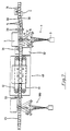
Wie aus der in der Fig. 1 schematisch dargestellten
Draufsicht erkennbar ist, werden die zu prüfenden Flaschen 5
durch einen kontinuierlich antreibbaren Zuförderer 14 der
Inspektionsmaschine zugeführt. Die durch den Zuförderer 14,
z.B. ein Plattenförderband, in einer geschlossenen Reihe
aufrechtstehend transportierten Flaschen 5 werden durch
Führungsgeländer 30 auf ein parallel angeordnetes, mit
erhöhter Geschwindigkeit synchron zum Zuförderer 14
angetriebenes Förderband 4 überführt, wobei durch den
Geschwindigkeitssprung Lücken bzw. Zwischenabstände im
Flaschenstrom erzeugt werden. Diese Zwischenabstände sind zur
Durchführung der Seitenwandkontrolle notwendig.As shown schematically in FIG. 1
The
Die Seitenwandkontrolle erfolgt durch eine am Förderband 4
angeordnete Inspektionsstation 1, die im wesentlichen aus
einem diffuses Licht abstrahlenden Leuchtschirm 2, einer
Kamera 3 und zwischen dem Förderband 4 und der Kamera 3
angeordneten Spiegeln zur Erzeugung der Strahlengänge 6, 7
und 8 besteht. Außerdem ist die Inspektionsstation 1 mit
einer zweiten Kamera 15 zur Kontur-, Höhen- und/oder
Farberkennung ausgestattet. In Förderrichtung gesehen hinter
der Inspektionsstation 1 ist eine ansteuerbare
Auswerfereinrichtung 31 an einer Seite des Transportbandes 4
plaziert, der gegenüberliegend ein Auffangbehälter 32
zugeordnet ist. Mit der Auswerfereinrichtung 31, z.B. ein
quer zur Förderrichtung impulsartig vor- und
zurücksteuerbarer Pusher oder Stößel, können durch die zweite
Kamera 15 erkannte Fremdflaschen, die beispielsweise einen
bestimmten Durchmesser oder eine vorgebbare Höhe
überschreiten, zum Schutz nachfolgender
Inspektionseinrichtungen vom Förderband 4 entfernt werden.
Die Ansteuerung der beiden Kameras 3, 15 und der
Auswerfereinrichtung 31 erfolgt unter Berücksichtigung der
Fördergeschwindigkeit durch eine der Inspektionsstation 1
vorgeordnete Triggerlichtschranke 33.The side wall is checked by a
Der Inspektionsstation 1 zur Seitenwandkontrolle ist außerdem
eine zweite Inspektionsstation 40 nachgeordnet. In dieser
Inspektionsstation können die Flaschen 5 durch zwei
gegenüberliegend angeordnete, synchron zum Förderband 4
antreibbare Riemen 41 seitlich an der Mantelfläche
eingeklemmt und bodenfrei über mehrere
Inspektionseinrichtungen zur Boden-, Mündungskontrolle oder
Restflüssigkeitserkennung transportiert werden. Nach Abschluß
dieser Inspektionsvorgänge werden die Flaschen von den Riemen
41 auf ein nachfolgendes Förderband 45 abgestellt und
freigegeben.The
Hinter der zweiten Inspektionsstation 40 ist wiederum eine
ansteuerbare Auswerfereinrichtung 46 mit einem
gegenüberliegend am Transportband 45 angeordneten
Auffangbehälter 47 plaziert, um durch die erste oder zweite
Inspektionsstation 1, 40 als nicht weiterverwendbar erkannte
Flaschen, z.B. mit Ausbrüchen an der Mündung, ausscheiden zu
können. Dahinterliegend ist eine dritte Auswerfereinrichtung
48 zur Ausschleusung von evtl. nach einer erneuten Reinigung
weiter verwendbaren Flaschen auf einen parallel zum
Förderband 45 angeordneten Förderer 49 vorgesehen.Behind the
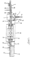
Aus der Fig. 2 ist die Anordnung der die drei Strahlengänge
6, 7, 8 erzeugenden Spiegel ersichtlich. Die beiden
Strahlengänge 6 und 7 sind zur optischen Achse 12 der Kamera
3 symmetrisch zu den Spiegeln 6a und 6b des Strahlenganges 6
positioniert. Die beiden Spiegel 6b und 7b sind so zueinander
ausgerichtet, daß sich die Strahlengänge 6 und 7 unter einem
bestimmten Winkel, z.B. 60 Grad, bezogen auf die Mittelachsen
6' und 7' der Strahlengänge, in einem über dem Förderband 4
liegenden Kreuzungsbereich 9 treffen. Ein dritter
Strahlengang 8 wird, ausgehend von der Kamera 3, durch drei
Spiegel 8a, 8b, 8c, so umgelenkt, daß die Mittelachse 8'
dieses dritten Strahlenganges 8 im Kreuzungsbereich 9 den von
den beiden Mittelachsen 6' und 7' eingeschlossenen Winkel
halbiert. Der Spiegel 8c ist so positioniert, daß die in Fig.
2 dargestellte senkrechte Projektion der Mittelachse 8' an
der gemeinsamen Schnittstelle 10 der drei Mittelachsen 6', 7'
und 8' sowohl normal zur Symmetrielinie 11 der zu prüfenden
Flasche 5 als auch zur Förderrichtung des Förderbandes 4
ausgerichtet ist. Die für die Seitenwandkontrolle zuständige
Kamera 3 ist mit einem Flächenarray ausgestattet, auf dem die
drei Strahlengänge 6, 7 und 8 nebeneinander abgebildet
werden. Der Kamera 3 ist eine nicht dargestellte
Auswerteinrichtung zugeordnet, die das von der Kamera
aufgenommene Bild programmgesteuert auswertet. Das
Auswertprogramm kann so gestaltet sein, daß von jedem
Strahlengang jeweils nur der mittlere Bildbereich ausgewertet
wird, während die Randbereiche ausblendbar sind bzw.
ignoriert werden, um Ungenauigkeit in den Randbereichen der
aufgenommenen Bilder infolge der optischen Verzerrungen an
den stark gekrümmten Flaschenrändern zu vermeiden.2 shows the arrangement of the three
Außerdem ist der Inspektionsstation 1 eine zweite Kamera 15
zur Kontrolle der Kontur- und/oder Höhe und/oder Farbe der zu
prüfenden Flaschen zugeordnet. Diese zweite Kamera 15 ist so
angeordnet, dass ihr Strahlengang 16 ungehindert zwischen den
Spiegeln der Seitenwandkontrolleinrichtung hindurch auf eine
sich gerade im Kreuzungsbereich 9 befindende Flasche 5
treffen kann. Insbesondere ist die optische Achse 17 der
Kamera 15 so ausgerichtet, dass sie ebenfalls durch die
gemeinsame Schnittstelle 10 der drei Strahlengänge 6, 7 und 8
der Seitenwandkontrolle verläuft. Dadurch sind die beiden
Kameras 3 und 15 mit einem gemeinsamen Steuersignal zur
gleichzeitigen Bildaufnahme ansteuerbar. Besonders günstig
ist eine Anordnung des Strahlengangs 16 der Kamera 15, bei
der die senkrechte Projektion der optischen Achse 17 die
senkrechte Projektion der Mittelachse 8' bzw. die optische
Achse 12 der Kamera 3 mit einem Winkel von ca. 25 Grad
kreuzt. The
Abweichend von der Darstellung in Fig. 2 können die beiden
Kameras 3 und 15 mit ihren optischen Achsen 12 und 17
senkrecht zur Förderebene der Flaschen stehend angeordnet
werden. Diese Alternative ist in der Fig. 2 mit gestrichelten
Umrißlinien angedeutet und in den Fig. 3 bis 5 dargestellt.Deviating from the representation in Fig. 2, the two
Diese Anordnung gestattet eine sehr kompakte, platzsparende
Bauweise der Inspektionsstation 1, da der quer zum Förderband
4 erforderliche Abstand im Vergleich zur Ausführung nach Fig.
2 deutlich verkürzt werden kann.This arrangement allows a very compact, space-saving
Construction of the
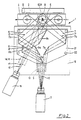
In der in Fig. 3 dargestellten Seitenansicht der Fig. 2 sind
zwecks der besseren Übersicht nur die Kamera 3 und die beiden
dem Strahlengang 7 zugeordneten Spiegel 7a und 7b
dargestellt. Eingezeichnet ist der Strahlenverlauf der in
Fig. 2 mit 7' bezeichneten Mittelachse. Die Positionierung
der ebenen Spiegel 7a und 7b (und auch der übrigen Spiegel)
erfolgt durch zwei mit Abstand zueinander parallel, jeweils
in einer horizontalen Ebene liegende Positionierplatten 21,
die durch Distanzstangen 22 auf einer Grundplatte 19
befestigt sind. Die Positionierplatten 21 besitzen der Dicke
und Breite der Spiegel entsprechende Schlitze (siehe Fig. 2).
Die Spiegel sind durch diese Schlitze von oben her einführbar
und stehen mit ihrer unteren Kante auf der Grundplatte 19.
Dadurch ist im Falle von Beschädigungen ein einfacher und
schneller Austausch der Spiegel möglich.3 are the side view of FIG. 2 shown in FIG
only
Auf der oberen Positionierplatte 21 ist eine Führung 20
befestigt, an der die senkrecht stehend angeordnete Kamera 3
mittels eines Kemmstücks 35 höhenverstellbar gehalten wird
Das Klemmstück besitzt außerdem ein Drehgelenk 36 zur
Einstellung des Auftreffwinkels der optischen Achse 12 der
Kamera 3 auf den darunter auf der Grundplatte 19 angeordneten
Spiegel 13. A
In Fig. 4 sind die dem mittleren Strahlengang 8 zugeordneten
Spiegel 8a, 8b und 8c dargestellt, wobei ebenfalls zur
besseren Übersicht alle übrigen Spiegel nicht eingezeichnet
sind.4 are those assigned to the
Die Fig. 5 entspricht weitgehend der Fig. 4, wobei zusätzlich
die Kamera 15 zur Kontur- und Höhenerkennung mit ihrem
Strahlengang 16 angedeutet ist. Wegen der senkrechten
Anordnung der Kamera 15 ist ebenfalls ein den Strahlengang 16
aus der senkrechten Richtung quer zur Symmetrielinie 11 der
zu prüfenden Flasche 5 umlenkender Spiegel 18 erforderlich.
Die zweite Kamera 15 ist in nicht dargestellter Weise,
ähnlich wie die Kamera 3, an der oberen Positionierplatte 21
einstellbar befestigt.5 largely corresponds to FIG. 4, with additional
the
Zur Kontur- und Höhenkontrolle reicht die Erfassung des
Schulter- und Kopfbereiches der Flaschen 5. Dadurch genügt im
Vergleich zu den Strahlengängen der Seitenwandkontrolle eine
kürzere Länge des Strahlengangs 17, so dass die Kamera 15
ohne zusätzliche Umlenkspiegel ähnlich nahe an der Flasche 5
angeordnet werden kann, wie die zur Seitenwandkontrolle
dienende Kamera 3.For contour and height control, the detection of the
Shoulder and head area of the
Die Fig. 6 zeigt eine alternative Spiegelanordnung zur
Erzeugung der zur Seitenwandkontrolle erforderlichen
Strahlengänge. Die dargestellte Spiegelanordnung erzeugt
ebenfalls zwei zur optischen Achse 12 der Kamera 3
symmetrisch ausgebildete Strahlengänge 6 und 7, von denen nur
die Mittelachsen 6' und 7' dargestellt sind. Zu diesem Zweck
sind jeweils Spiegel 6A, 6B und 7A, 7B vorhanden, die mit
einem ausreichenden Zwischenabstand zur optischen Achse 12
angeordnet sind, derart, dass die den dritten Strahlengang 8
bildenden Spiegel 8A, B, C vor den vorgenannten Spiegeln der
beiden übrigen Strahlengänge plaziert werden können, und der
zur Flasche 5 führende Abschnitt des Strahlengangs 8 zwischen
den zu den Strahlengängen 6 bis 7 gehörenden Spiegeln
ungehindert hindurchtreten kann.6 shows an alternative mirror arrangement for
Generation of the necessary for the sidewall control
Beam paths. The mirror arrangement shown generates
likewise two to the
Abweichend von den dargestellten Ausführungen sind auch Spiegelanordnungen denkbar und vorteilhaft, die zur Seitenwandkontrolle mehr als drei Strahlengänge erzeugen.Also differ from the versions shown Mirror arrangements conceivable and advantageous for Sidewall control generate more than three beam paths.
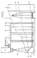
Die in Fig. 7 dargestellte Inspektionsmaschine besitzt
grundsätzlich den gleichen mechanischen Aufbau wie die
Inspektionsmaschine nach Fig. 1. Zusätzlich verfügt sie aber
über eine Inspektionsstation 100 für eine zweite
Seitenwandkontrolle der Flaschen 5. Diese Inspektionsstation
100 ist unmittelbar hinter den Riemen 41 der
Inspektionsstation 40 am Förderband 45 angeordnet. Die
Spiegelanordnung der Inspektionsstation 100 stimmt mit der
der Inspektionsstation 1 überein. Beide Riemen 41 werden
synchron zu den Förderbändern 4 und 45 angetrieben,
allerdings mit einer geringen Geschwindigkeitsdifferenz
zueinander. In Abhängigkeit der eingestellten
Geschwindigkeitsdifferenz werden die Flaschen während der
Überführung vom Förderband 4 auf das Förderband 45 um einen
bestimmten Winkel, vorzugsweise ca. 90 Grad, um ihre
Hochachse gedreht und anschließend ohne Eigendrehung durch
die Inspektionsstation 100 geführt. Nachfolgend kann die
Ausscheidung unbrauchbarer Flaschen 5 vorgenommen werden, wie
vorhergehend zur Fig. 1 bereits erläutert wurde.The inspection machine shown in Fig. 7 has
basically the same mechanical structure as that
Inspection machine according to Fig. 1. But it also has
via an
Die Geschwindigkeitsdifferenz zwischen den beiden Riemen 41
ist so einstellbar, dass bei einer Umstellung der
Inspektionsmaschine auf Flaschen mit einem anderen Umfangsmaß
der Drehwinkel der Flaschen beim Durchfahren der
Riemenstrecke konstant 90 Grad beträgt. Zu diesem Zweck ist
beispielsweise einer der beiden Riemen 41 antriebsmäßig mit
den Förderbändern 4 und/oder 45 verbunden, während der zweite
Riemen 41 über einen eigenen, regelbaren Antrieb mit einer
programmierbaren Steuerung verfügt. Die Umstellung des
Übersetzungsverhältnisses zwischen den beiden Riemen 41 kann
dann auf Knopfdruck erfolgen.The speed difference between the two
Eine Seitenwandkontrolle mit zwei Inspektionsstationen 1 und
100 hat den Vorteil, dass die erforderlichen Zwischenstände
im Flaschenstrom klein gehalten werden können, wodurch auch
die Flaschentransportgeschwindigkeit bei einer vorgegebenen
Leistung niedriger ist, als bei einer Kontrolle der gesamten
Flaschenseitenwand mit nur einer Inspektionsstation. Dies ist
auf den kleineren Winkel zwischen den Strahlen 6 und 7
zurückzuführen, der gewählt werden kann, z.B.60 Grad, da die
Flaschenseitenwand beim Passieren einer der beiden
Inspektionsstationen 1 und 100 nicht vollumfänglich
aufgenommen werden muß. Zusätzlich ergeben sich durch den
kleineren Winkel optische Vorteile bei der Bildäufnahme. Bei
einer Seitenwandkontrolle mit nur einer einzigen
Inspektionsstation ist dagegen zwischen den Strahlen 6 und 7
ein Winkel von über 100 Grad zur vollständigen Erfassung
einer Flaschenseitenwand erforderlich.A side wall control with two
Claims (24)
- Inspection machine for translucent bottles (5) or the like, comprising an inspection station (1) for sidewall control which includes an illumination device (2), an image recording device (3) and a mirror arrangement which is located between a bottle under test and the image recording device and produces lightbeams, and a transport device (4) which guides the bottles (5) on single track through the lightbeams, characterised by a mirror arrangement (6a to 8c) which produces at least three lightbeams which image the sidewall of a bottle under test from peripherally different directions onto a common image recording device, and one lightbeam (8) is deflected by two mirrors (8a, 8c) located on the optical axis (12) of the image recording device (3) and a mirror (8b) arranged thereinbetween and alongside the optical axis (12), and the mirror (8b) positioned alongside the optical axis deflects the lightbeam (8) from the first to the second of the two mirrors (8a, 8c) which are located on the optical axis.
- Inspection machine according to Claim 1, characterised in that all lightbeams (6, 7, 8) intersect in a common intersecting area (9) through which the bottles (5) are transported by means of the transport device (4).
- Inspection machine according to at least one of the above claims, characterised in that the centre axes (6', 7', 8') of all lightbeams (6, 7, 8) coincide in a common intersecting point (10), and the bottles (5) are guided by means of the transport device (4) through the intersecting point (10), in particular in such a manner that the line of symmetry (11) of the bottles virtually passes the intersecting point (10), and an image is recorded at the moment of coincidence of the line of symmetry with said intersecting point.
- Inspection machine according to at least one of the above claims, characterised in that all lightbeams (6, 7, 8) are of identical length; in particular the centre axes (6', 7', 8') of the lightbeams from the image recording device (3) up to a common intersecting point (10) have a coinciding length, preferably between 750 and 1,500 mm, in particular 1,240 m.
- Inspection machine according to at least one of the above claims, characterised in that the optical axis (12) of the image recording device (3) is aligned both normally to the transport direction of the bottles in the inspection station (1) and at least sectionally transversely to the line of symmetry (11) of the bottles (5).
- Inspection machine according to one of the above claims, characterised in that two lightbeams (6, 7) are set symmetrically to the optical axis (12) of the image recording device (3), the lightbeams are deflected preferably by two respective mirrors (6a, 6b and 7a, 7b) arranged between the image recording device (3) and the illuminating device (2) so that the lightbeams (6, 7) are oriented from the image recording device initially through a first pair of mirrors (6a, 7a) away from the optical axis (12) and through a downstream second pair of mirrors (6b, 7b) towards the optical axis (12) to the sidewall area of a bottle under test (5), and the intersecting point (10) of the centre axes (6', 7') of the lightbeams lies in particular on the optical axis (12) of the image recording device (3).
- Inspection machine according to at least one of the above claims, characterised in that between two symmetrically extending lightbeams (6, 7) is arranged a third, preferably centrally oriented lightbeam (8), and its centre axis (8') is at least sectionally flush with the optical axis (12) of the image recording device (3).
- Inspection machine according to at least one of the above Claims 6 to 7, characterised in that that the mirrors (8A, 8B, 8C) which are associated with the third lightbeam (8) are arranged, as seen from image recording device 3 to illuminating device 2, in front of the mirrors (6A, 6B, 7A, 7B) of the symmetrically extending lightbeams (6, 7).
- Inspection machine according to at least one of the above claims, characterised in that at least the section of a third lightbeam (8) coinciding with the sidewall of a bottle can pass through an intermediate space between the mirrors (6A, 6B, 7A, 7B) which are associated with the remaining lightbeams (6, 7).
- Inspection machine according to at least one of the above claims, characterised in that a mirror (8a) associated with a third lightbeam (8) is arranged in front of a first pair of mirrors (6a, 7a) of two symmetrically extending lightbeams (6, 7), and therebehind a further mirror (8c).
- Inspection machine according to at least one of the above claims, characterised in that the optical axis (12) of the image recording machine (3) is sectionally oriented essentially parallel to the line of symmetry (11) of the bottles (5), and the optical axis (3), commencing from the image recording device (3), is deflected by a mirror (13) transversely to the line of symmetry (11) of the bottles (5).
- Inspection machine according to Claim 11, characterised in that the image recording device (3) is arranged laterally along the transport device (4) at a distance above its conveying plane.
- Inspection machine according to at least one of the above claims, characterised in that two lightbeams (6, 7) at an angular range of between 45 and 80 degrees, in particular 60 degrees, coincide with a bottle under test (5) relative to the centre axes (6', 7').
- Inspection machine according to Claim 13, characterised in that a third lightbeam (8) coincides with a bottle under test (5) whilst halving the angle included by the remaining lightbeams (6, 7).
- Inspection machine according to at least one of the above claims, characterised in that the inspection station (1) comprises a second image recording device (15) for contour and/or height and/or colour recognition of the bottles (5), and its lightbeam (16) extends through the intersecting area (9) of the lightbeams (6, 7, 8) of the sidewall control, in particular the optical axis (17) essentially through the intersecting point (10) of the centre axes (6', 7', 8') of the light beams of the sidewall control, so that image recording of a bottles can be carried out by both image recording devices (3, 15) at approximately the same time.
- Inspection machine according to Claim 15, characterised in that the optical axis (17) of the second image recording device (15) extends sectionally essentially parallel to the line of symmetry (11) of the bottles (5) and is deflected by a mirror (18) transversely to the symmetry line (11) of the bottles (5).
- Inspection machine according to at least one of Claims 15 or 16, characterised in that the section of the optical axes (12, 17) of the image recording devices (3, 15) which coincide transversely to the line of symmetry (11) of the bottles (5) include an acute angle in the range of preferably between 15 and 35 degrees, in particular 25 degrees.
- Inspection machine according to at least one of the above claims, characterised in that mirrors (6a, 6b, 7a, 7b, 8a, 8b, 8c, 13) are arranged to stand on a common base plate (19).
- Inspection machine according to Claim 18, characterised in that the mirror (6a, 6b, 7a, 7b, 8a, 8b, 8c) is held by parallel positioning plates (21) which are provided with slots.
- Inspection machine according to at least one of the above claims, characterised in that the image recording devices (3, 15) include a surface matrix, and in particular the lightbeams (6, 7, 8) of the sidewall control are imaged alongside each other on the surface matrix of the image recording device (3).
- Inspection machine according to at least one of the above claims, characterised in that the image recording is made by means of an electronic camera, in particular CCD cameras.
- Inspection machine according to at least one of the above claims, characterised in that the bottles (5) pass towards the side wall control one after the other two inspection stations (1, 100) at different rotary positions.
- Inspection machine according to Claim 22, characterised in that between the inspection stations (1, 100) is arranged a device for rotating the bottles (5), preferably composed of two belts (41) positioned opposite each other at the casing surface of the bottles, which can be driven at different speed synchronously to the transport device (4).
- Inspection machine according to Claim 23, characterised in that between the belts (41) which engage the bottles is set a difference in speed for rotation of the bottles in such a manner that the rotary angle of the bottles whilst passing the belts (41) remains constant when resetting to bottles of a different peripheral size.
Applications Claiming Priority (5)
| Application Number | Priority Date | Filing Date | Title |
|---|---|---|---|
| DE19939311405 DE9311405U1 (en) | 1993-07-30 | 1993-07-30 | Inspection machine |
| DE9311405U | 1993-07-30 | ||
| DE19939313115 DE9313115U1 (en) | 1993-09-01 | 1993-09-01 | Inspection machine |
| DE9313115U | 1993-09-01 | ||
| EP94924822A EP0663069B1 (en) | 1993-07-30 | 1994-07-29 | Inspection machine |
Related Parent Applications (1)
| Application Number | Title | Priority Date | Filing Date |
|---|---|---|---|
| EP94924822A Division EP0663069B1 (en) | 1993-07-30 | 1994-07-29 | Inspection machine |
Publications (3)
| Publication Number | Publication Date |
|---|---|
| EP1130384A1 EP1130384A1 (en) | 2001-09-05 |
| EP1130384A8 EP1130384A8 (en) | 2001-12-05 |
| EP1130384B1 true EP1130384B1 (en) | 2003-05-14 |
Family
ID=25961073
Family Applications (3)
| Application Number | Title | Priority Date | Filing Date |
|---|---|---|---|
| EP94924822A Expired - Lifetime EP0663069B1 (en) | 1993-07-30 | 1994-07-29 | Inspection machine |
| EP01112238A Expired - Lifetime EP1130384B1 (en) | 1993-07-30 | 1994-07-29 | Inspecting machine |
| EP05005396A Expired - Lifetime EP1553405B1 (en) | 1993-07-30 | 1994-07-29 | Inspecting machine |
Family Applications Before (1)
| Application Number | Title | Priority Date | Filing Date |
|---|---|---|---|
| EP94924822A Expired - Lifetime EP0663069B1 (en) | 1993-07-30 | 1994-07-29 | Inspection machine |
Family Applications After (1)
| Application Number | Title | Priority Date | Filing Date |
|---|---|---|---|
| EP05005396A Expired - Lifetime EP1553405B1 (en) | 1993-07-30 | 1994-07-29 | Inspecting machine |
Country Status (7)
| Country | Link |
|---|---|
| US (1) | US5729340A (en) |
| EP (3) | EP0663069B1 (en) |
| JP (1) | JP3604388B2 (en) |
| KR (1) | KR950703733A (en) |
| BR (1) | BR9405536A (en) |
| DE (3) | DE59410463D1 (en) |
| WO (1) | WO1995004267A1 (en) |
Cited By (1)
| Publication number | Priority date | Publication date | Assignee | Title |
|---|---|---|---|---|
| EP1750117A2 (en) | 2005-08-02 | 2007-02-07 | Krones AG | Device and method for identifying properties of bottles |
Families Citing this family (51)
| Publication number | Priority date | Publication date | Assignee | Title |
|---|---|---|---|---|
| GB9416406D0 (en) * | 1994-08-13 | 1994-10-05 | Univ Of Huddersfield | Colour inspection system |
| AU9315498A (en) * | 1997-10-10 | 1999-05-03 | Northeast Robotics Llc | Imaging method and system with elongate inspection zone |
| US5895911A (en) * | 1998-01-22 | 1999-04-20 | Emhart Glass S.A. | Glass container body check detector |
| AU742980B2 (en) * | 1999-10-13 | 2002-01-17 | Kawasaki Jukogyo Kabushiki Kaisha | Random work arranging device |
| DE10027226C1 (en) | 2000-05-31 | 2001-10-18 | Krones Ag | Transparent drinks bottle inspection method has single camera used to provide 2 images evaluated separately with variation of exposure timing between images |
| DE10164058B4 (en) * | 2000-12-30 | 2008-06-12 | Krones Ag | inspection device |
| KR20010079284A (en) * | 2001-07-02 | 2001-08-22 | 서용교 | Desired Grain Sorting out of Miscellaneous Grain Crop by color reflected from the Mirror |
| KR20030011175A (en) * | 2001-07-28 | 2003-02-07 | 삼성전자주식회사 | Soldering inspection apparatus |
| KR20030046616A (en) * | 2001-12-06 | 2003-06-18 | 삼성전자주식회사 | Micro-bubble analyzing apparatus for high-purity glass tube using laser light scattering |
| DE10339473A1 (en) * | 2003-08-27 | 2005-03-24 | Seidenader Maschinenbau Gmbh | Device for testing products |
| DE102004013774B4 (en) | 2004-03-20 | 2018-10-04 | Khs Gmbh | Inspection device for containers made of glass or a translucent material |
| FR2873206B1 (en) | 2004-07-13 | 2007-11-23 | Iris Inspection Machines Sa | MACHINE FOR DETECTING DEFECTS OF A TRANSPARENT OR TRANSLUCENT OBJECT |
| DE102005017957A1 (en) * | 2005-04-18 | 2006-10-26 | Khs Ag | inspection device |
| DE102005023534B4 (en) * | 2005-05-21 | 2007-04-12 | Krones Ag | Device for inspecting labeled vessels |
| DE202005020478U1 (en) * | 2005-12-30 | 2007-05-24 | Krones Ag | Label examining device for containers, has camera for imaging container surface equipped with labels, where optical mechanism is arranged between camera and container |
| JP4809168B2 (en) * | 2006-09-19 | 2011-11-09 | アサヒ飲料株式会社 | Bottle container inspection device |
| US7626158B2 (en) * | 2006-10-23 | 2009-12-01 | Emhart Glass S.A. | Machine for inspecting glass containers |
| DE102007020460B3 (en) * | 2007-04-27 | 2009-01-08 | Krones Ag | Inspection device and inspection method for containers |
| DE102007025524B4 (en) * | 2007-05-31 | 2010-07-29 | Khs Ag | Opto-electrical detection system |
| DE102007036621A1 (en) | 2007-07-31 | 2009-02-05 | Miho Inspektionssysteme Gmbh | Bottle e.g. beverage bottle, testing method for use in beverage industry, involves analyzing bottle image by image sensor and image processing system, and using self-luminous image for detecting preselected characteristics of bottle |
| JP5298327B2 (en) * | 2008-08-26 | 2013-09-25 | キリンテクノシステム株式会社 | Foreign matter inspection apparatus and foreign matter inspection system |
| DE102008063076B3 (en) * | 2008-12-24 | 2010-04-29 | Krones Ag | Bottle inspection device with image-corrected mirror cabinet |
| DE102009020919A1 (en) * | 2009-05-12 | 2010-11-18 | Krones Ag | Device for detecting elevations and / or depressions on bottles, in particular in a labeling machine |
| DE102010004972A1 (en) * | 2010-01-18 | 2011-07-21 | Krones Ag, 93073 | Object i.e. glass bottle, inspecting method for filling and packing system, involves outputting data sets by inspection devices, where data sets characterize inspected areas of object and are associated with each other |
| GB2482473A (en) * | 2010-06-29 | 2012-02-08 | Constar Internat Uk Ltd | Inspection of articles |
| EP2635519A4 (en) * | 2010-11-01 | 2015-05-20 | Make All Corp | Raised vial stopper detection system |
| DE102011004584A1 (en) * | 2011-02-23 | 2012-08-23 | Krones Aktiengesellschaft | Method and apparatus for detecting bubbles and / or wrinkles on labeled containers |
| AT510849B1 (en) * | 2011-06-28 | 2012-07-15 | Medek & Schoerner Gmbh | DEVICE FOR THE OPTICAL RECORDING OF OBJECTS |
| DE102011083037A1 (en) | 2011-09-20 | 2013-03-21 | Krones Aktiengesellschaft | Method and device for inspection of containers and preforms |
| DE102012009783B3 (en) * | 2012-05-18 | 2013-08-14 | Khs Gmbh | Method and device for inspection of empty bottles |
| US20150246750A1 (en) * | 2012-10-04 | 2015-09-03 | Fuji Seal International, Inc. | Container with shrink-fit label, shrink-fit label, and manufacturing method for container with shrink-fit label |
| DE102014102450A1 (en) * | 2014-02-25 | 2015-08-27 | Khs Gmbh | Inspection device with inverse foil lens |
| DE102014104078B4 (en) | 2014-03-25 | 2019-04-25 | Krones Ag | Inspection device and inspection method for the transmitted light inspection of containers |
| DE102014106380A1 (en) | 2014-05-07 | 2015-11-12 | Krones Ag | Method and device for transporting containers |
| DE102014216188A1 (en) * | 2014-08-14 | 2016-02-18 | Krones Ag | Optical inspection method and optical inspection device for containers |
| DE102015204412A1 (en) | 2015-03-11 | 2016-09-15 | Krones Ag | Inspection device for inspecting bottles |
| DE102015218356A1 (en) * | 2015-09-24 | 2017-03-30 | Krones Ag | Inspection method and apparatus for optical transmitted light inspection of unlabeled containers |
| US20170244904A1 (en) * | 2016-02-18 | 2017-08-24 | The Boeing Company | Optical monitoring system and method for imaging a component under test |
| PL3208782T3 (en) | 2016-02-22 | 2023-04-24 | Wincor Nixdorf International Gmbh | Empties returning device |
| WO2017204766A2 (en) | 2016-05-26 | 2017-11-30 | Turkiye Sise Ve Cam Fabrikalari A. S. | A quality control system for semi-finished glass products |
| WO2017204765A2 (en) | 2016-05-26 | 2017-11-30 | Turkiye Sise Ve Cam Fabrikalari A. S. | A quality control system for household glass products |
| FR3056296B1 (en) * | 2016-09-19 | 2018-10-19 | Tiama | INSTALLATION FOR THE OPTICAL INSPECTION OF GLASS CONTAINERS OUTPUT OF FORMING MACHINE |
| DE102017201776B4 (en) * | 2017-02-03 | 2023-03-09 | Krones Ag | Inspection apparatus and method for sidewall and closure head inspection of containers |
| DE102017206971A1 (en) | 2017-04-26 | 2018-10-31 | Krones Aktiengesellschaft | Inspection method and apparatus for image inspection of containers |
| UY38287A (en) | 2018-07-30 | 2019-08-30 | Grifols Worldwide Operations Ltd | PROCEDURE AND DEVICE TO DETECT DEFECTS IN THE CLOSURE OF ENCAPSULATED VIALS |
| EP3715835A1 (en) * | 2019-03-29 | 2020-09-30 | Mettler-Toledo Pharmacontrol Electronic GmbH | Inspection system |
| CN110006598B (en) * | 2019-04-24 | 2024-03-12 | 山东省科学院海洋仪器仪表研究所 | Penicillin bottle online leakage detection device and method |
| FR3109820B1 (en) * | 2020-04-30 | 2024-01-19 | Tiama | Installation and method for ensuring the simultaneous adjustment of optical systems depending on the diameter of the containers |
| US11047803B1 (en) * | 2020-09-10 | 2021-06-29 | Applied Vision Corporation | Glass container inspection system |
| EP4251339A2 (en) * | 2020-11-24 | 2023-10-04 | Koska Family Limited | Systems and methods for blow-fill-seal (bfs) product inspection |
| IT202200001496A1 (en) * | 2022-01-28 | 2023-07-28 | Marco Lottici | APPARATUS AND METHOD FOR THE INSPECTION OF CONTAINERS, IN PARTICULAR GLASS BOTTLES WITH THREADED NECKS |
Family Cites Families (17)
| Publication number | Priority date | Publication date | Assignee | Title |
|---|---|---|---|---|
| GB977059A (en) * | 1960-01-28 | 1964-12-02 | Emi Ltd | Improvements relating to optical inspection apparatus |
| US3932042A (en) * | 1974-05-20 | 1976-01-13 | Barry-Wehmiller Company | Container inspection apparatus and method of inspection |
| US4025201A (en) * | 1975-04-21 | 1977-05-24 | Ball Brothers Service Corporation | Method and apparatus for video inspection of articles of manufacture by decussate paths of light |
| GB1600400A (en) * | 1977-10-13 | 1981-10-14 | Ti Fords Ltd | Bottle inspection apparatus |
| JPS5546172A (en) * | 1978-09-29 | 1980-03-31 | Kirin Brewery Co Ltd | Detector for foreign material |
| ES8205060A1 (en) * | 1980-03-28 | 1982-05-16 | Udaras Na Gaeltachta | Apparatus for the inspection of translucent containers. |
| DE3035077A1 (en) * | 1980-09-17 | 1982-04-22 | Siemens AG, 1000 Berlin und 8000 München | Optical bottle inspection appts. - has symmetrical arrangement of mirrors behind bottle reflecting light into TV camera |
| US4553217A (en) * | 1981-07-08 | 1985-11-12 | Ball Corporation | Glassware gauging system |
| US4500203A (en) * | 1982-09-30 | 1985-02-19 | Owens-Illinois, Inc. | Method and apparatus for inspecting articles |
| US4509081A (en) * | 1982-11-29 | 1985-04-02 | Industrial Automation Corp. | Optical system for automatic sorting and inspection equipment |
| US4586080A (en) * | 1984-03-22 | 1986-04-29 | Ball Corporation | Method and apparatus for video inspection of articles of manufacture |
| US4691231A (en) * | 1985-10-01 | 1987-09-01 | Vistech Corporation | Bottle inspection system |
| JPH0799326B2 (en) * | 1986-08-30 | 1995-10-25 | 株式会社マキ製作所 | Appearance inspection method and apparatus for spherical articles |
| US4751386A (en) * | 1987-03-31 | 1988-06-14 | Emhart Industries, Inc. | Lean detector for determining the offset of an axis of symmetry of a container from its norm |
| US4958223A (en) * | 1988-09-16 | 1990-09-18 | Owens-Brockway Glass Container Inc. | Inspection of container finish |
| JP2944092B2 (en) * | 1989-01-27 | 1999-08-30 | 株式会社マキ製作所 | Appearance inspection equipment for goods |
| US5256871A (en) * | 1992-12-22 | 1993-10-26 | Emhart Glass Machinery Investments Inc. | Machine for video inspection of glass containers with intersecting light beams |
-
1994
- 1994-07-29 EP EP94924822A patent/EP0663069B1/en not_active Expired - Lifetime
- 1994-07-29 EP EP01112238A patent/EP1130384B1/en not_active Expired - Lifetime
- 1994-07-29 KR KR1019950700954A patent/KR950703733A/en not_active Application Discontinuation
- 1994-07-29 WO PCT/EP1994/002523 patent/WO1995004267A1/en active IP Right Grant
- 1994-07-29 DE DE59410463T patent/DE59410463D1/en not_active Expired - Lifetime
- 1994-07-29 BR BR9405536-0A patent/BR9405536A/en not_active Application Discontinuation
- 1994-07-29 DE DE59410415T patent/DE59410415D1/en not_active Expired - Lifetime
- 1994-07-29 EP EP05005396A patent/EP1553405B1/en not_active Expired - Lifetime
- 1994-07-29 DE DE59410287T patent/DE59410287D1/en not_active Expired - Lifetime
- 1994-07-29 US US08/406,911 patent/US5729340A/en not_active Expired - Lifetime
- 1994-07-29 JP JP50557295A patent/JP3604388B2/en not_active Expired - Lifetime
Cited By (2)
| Publication number | Priority date | Publication date | Assignee | Title |
|---|---|---|---|---|
| EP1750117A2 (en) | 2005-08-02 | 2007-02-07 | Krones AG | Device and method for identifying properties of bottles |
| DE102005036796A1 (en) * | 2005-08-02 | 2007-02-08 | Krones Ag | Apparatus and method for detecting bottle characteristics |
Also Published As
| Publication number | Publication date |
|---|---|
| JPH08505947A (en) | 1996-06-25 |
| EP1130384A8 (en) | 2001-12-05 |
| DE59410287D1 (en) | 2003-06-18 |
| EP1553405A2 (en) | 2005-07-13 |
| US5729340A (en) | 1998-03-17 |
| EP0663069B1 (en) | 2005-11-02 |
| DE59410415D1 (en) | 2005-12-08 |
| EP1553405B1 (en) | 2011-03-30 |
| KR950703733A (en) | 1995-09-20 |
| JP3604388B2 (en) | 2004-12-22 |
| WO1995004267A1 (en) | 1995-02-09 |
| EP0663069A1 (en) | 1995-07-19 |
| DE59410463D1 (en) | 2011-05-12 |
| BR9405536A (en) | 1999-09-08 |
| EP1553405A3 (en) | 2005-09-07 |
| EP1130384A1 (en) | 2001-09-05 |
Similar Documents
| Publication | Publication Date | Title |
|---|---|---|
| EP1130384B1 (en) | Inspecting machine | |
| EP0228500B1 (en) | Method of and device for contactless measurement of the wheel profile of the wheels of railway wheel sets | |
| EP0338376B1 (en) | Method for reading optical markings on objects and device for its implementation | |
| DE10140009B4 (en) | Device for inspecting filled and closed bottles | |
| DE2617457A1 (en) | METHOD OF GENERATING A VISUAL IMAGE OF AN OBJECTIVE TO BE TESTED BY MEANS OF TRANSMISSION AND OPTICAL TESTING DEVICE | |
| EP0433666A2 (en) | Three-dimensional inspection apparatus for hollow bodies | |
| WO2013045131A1 (en) | Device and method for aligning containers | |
| EP0648151B1 (en) | Method and device for grading capsules | |
| DE3611536A1 (en) | Device for automatically testing transparent objects, in particular glass bottles | |
| EP2434276B1 (en) | Inspection procedure, inspection station and illumination and plotting device | |
| EP0708325B1 (en) | Method and device for the inspection of objects, especially bottles | |
| DE2848743B2 (en) | Method and device for determining a line of weakness in an ampoule | |
| DE2308910C3 (en) | Device for the automatic testing of hollow glasses, for example bottles with narrow necks, for damage and contamination by foreign bodies, lye and washing water residues | |
| DE2338295C2 (en) | Apparatus for detecting defects on opposing surfaces of a substantially flat path | |
| EP1419375B1 (en) | Method and device for inspecting filled, closed bottles, in particular in the lateral wall area near the base | |
| EP1371944A2 (en) | Apparatus for inspecting a container's mouth with respect to the presence of an inclination | |
| EP1811288A2 (en) | Method and device for inspecting closures | |
| DE2100729B2 (en) | Device for checking transparent containers for bubbles or defects | |
| DE102018121573B3 (en) | INSPECTION SYSTEM FOR INSPECTING A COVER SURFACE OF A THREE-DIMENSIONAL TEST OBJECT, AND THEIR USE AND RELATED METHOD | |
| DE10359781A1 (en) | Apparatus for inspecting returned empty bottles or packages moving along a conveyer belt using a line camera for recording light reflected from the bottles | |
| DE2655704B2 (en) | Device for detecting foreign bodies in glass bottles | |
| EP1577664B1 (en) | Inspection apparatus for bottles or similar containers | |
| DE3314686C2 (en) | Device for measuring the area of the projection of a test object onto a plane | |
| EP0263858A1 (en) | Device for checking the straightness and, if required, the height and/or distortions in vessels made of transparent material, preferably bottles | |
| DE19909903C1 (en) | Optoelectronic object inspection device uses 2 counter-rotating light deflectors for directing light from illuminated object onto stationary camera providing object image |
Legal Events
| Date | Code | Title | Description |
|---|---|---|---|
| PUAI | Public reference made under article 153(3) epc to a published international application that has entered the european phase |
Free format text: ORIGINAL CODE: 0009012 |
|
| 17P | Request for examination filed |
Effective date: 20010525 |
|
| AC | Divisional application: reference to earlier application |
Ref document number: 663069 Country of ref document: EP |
|
| AK | Designated contracting states |
Kind code of ref document: A1 Designated state(s): DE FR GB IT |
|
| RIN1 | Information on inventor provided before grant (corrected) |
Inventor name: RUPPELT, WOLFGANG Inventor name: KRONSEDER, HERMANN, DR.-ING. E.H. Inventor name: GRIESBECH, KARL Inventor name: HAERING, FRANZ |
|
| AKX | Designation fees paid |
Free format text: DE FR GB IT |
|
| GRAH | Despatch of communication of intention to grant a patent |
Free format text: ORIGINAL CODE: EPIDOS IGRA |
|
| GRAH | Despatch of communication of intention to grant a patent |
Free format text: ORIGINAL CODE: EPIDOS IGRA |
|
| GRAA | (expected) grant |
Free format text: ORIGINAL CODE: 0009210 |
|
| RIN1 | Information on inventor provided before grant (corrected) |
Inventor name: KRONSEDER, HERMANN, DR.-ING. E.H. Inventor name: GRIESBECK, KARL Inventor name: HAERING, FRANZ Inventor name: RUPPELT, WOLFGANG |
|
| AC | Divisional application: reference to earlier application |
Ref document number: 0663069 Country of ref document: EP Kind code of ref document: P |
|
| AK | Designated contracting states |
Designated state(s): DE FR GB IT |
|
| REG | Reference to a national code |
Ref country code: GB Ref legal event code: FG4D Free format text: NOT ENGLISH |
|
| REF | Corresponds to: |
Ref document number: 59410287 Country of ref document: DE Date of ref document: 20030618 Kind code of ref document: P |
|
| GBT | Gb: translation of ep patent filed (gb section 77(6)(a)/1977) | ||
| PLBE | No opposition filed within time limit |
Free format text: ORIGINAL CODE: 0009261 |
|
| STAA | Information on the status of an ep patent application or granted ep patent |
Free format text: STATUS: NO OPPOSITION FILED WITHIN TIME LIMIT |
|
| ET | Fr: translation filed | ||
| 26N | No opposition filed |
Effective date: 20040217 |
|
| PGFP | Annual fee paid to national office [announced via postgrant information from national office to epo] |
Ref country code: DE Payment date: 20130724 Year of fee payment: 20 |
|
| PGFP | Annual fee paid to national office [announced via postgrant information from national office to epo] |
Ref country code: GB Payment date: 20130724 Year of fee payment: 20 Ref country code: FR Payment date: 20130724 Year of fee payment: 20 |
|
| PGFP | Annual fee paid to national office [announced via postgrant information from national office to epo] |
Ref country code: IT Payment date: 20130717 Year of fee payment: 20 |
|
| REG | Reference to a national code |
Ref country code: DE Ref legal event code: R071 Ref document number: 59410287 Country of ref document: DE |
|
| REG | Reference to a national code |
Ref country code: GB Ref legal event code: PE20 Expiry date: 20140728 |
|
| PG25 | Lapsed in a contracting state [announced via postgrant information from national office to epo] |
Ref country code: DE Free format text: LAPSE BECAUSE OF EXPIRATION OF PROTECTION Effective date: 20140730 |
|
| PG25 | Lapsed in a contracting state [announced via postgrant information from national office to epo] |
Ref country code: GB Free format text: LAPSE BECAUSE OF EXPIRATION OF PROTECTION Effective date: 20140728 |