EP1553284B1 - Luftansaugdämpfungsanlage, insbesondere für aufgeladene Brennkraftmaschinen oder Klimaanlage, und Ansaugkanal mit solch einer Anlage - Google Patents
Luftansaugdämpfungsanlage, insbesondere für aufgeladene Brennkraftmaschinen oder Klimaanlage, und Ansaugkanal mit solch einer Anlage Download PDFInfo
- Publication number
- EP1553284B1 EP1553284B1 EP04292929A EP04292929A EP1553284B1 EP 1553284 B1 EP1553284 B1 EP 1553284B1 EP 04292929 A EP04292929 A EP 04292929A EP 04292929 A EP04292929 A EP 04292929A EP 1553284 B1 EP1553284 B1 EP 1553284B1
- Authority
- EP
- European Patent Office
- Prior art keywords
- air
- shells
- conduit section
- noises
- attenuating
- Prior art date
- Legal status (The legal status is an assumption and is not a legal conclusion. Google has not performed a legal analysis and makes no representation as to the accuracy of the status listed.)
- Expired - Lifetime
Links
Images


Classifications
-
- F—MECHANICAL ENGINEERING; LIGHTING; HEATING; WEAPONS; BLASTING
- F02—COMBUSTION ENGINES; HOT-GAS OR COMBUSTION-PRODUCT ENGINE PLANTS
- F02M—SUPPLYING COMBUSTION ENGINES IN GENERAL WITH COMBUSTIBLE MIXTURES OR CONSTITUENTS THEREOF
- F02M35/00—Combustion-air cleaners, air intakes, intake silencers, or induction systems specially adapted for, or arranged on, internal-combustion engines
- F02M35/12—Intake silencers ; Sound modulation, transmission or amplification
- F02M35/1205—Flow throttling or guiding
- F02M35/1216—Flow throttling or guiding by using a plurality of holes, slits, protrusions, perforations, ribs or the like; Surface structures; Turbulence generators
-
- F—MECHANICAL ENGINEERING; LIGHTING; HEATING; WEAPONS; BLASTING
- F02—COMBUSTION ENGINES; HOT-GAS OR COMBUSTION-PRODUCT ENGINE PLANTS
- F02M—SUPPLYING COMBUSTION ENGINES IN GENERAL WITH COMBUSTIBLE MIXTURES OR CONSTITUENTS THEREOF
- F02M35/00—Combustion-air cleaners, air intakes, intake silencers, or induction systems specially adapted for, or arranged on, internal-combustion engines
- F02M35/12—Intake silencers ; Sound modulation, transmission or amplification
- F02M35/1255—Intake silencers ; Sound modulation, transmission or amplification using resonance
- F02M35/1261—Helmholtz resonators
-
- F—MECHANICAL ENGINEERING; LIGHTING; HEATING; WEAPONS; BLASTING
- F02—COMBUSTION ENGINES; HOT-GAS OR COMBUSTION-PRODUCT ENGINE PLANTS
- F02M—SUPPLYING COMBUSTION ENGINES IN GENERAL WITH COMBUSTIBLE MIXTURES OR CONSTITUENTS THEREOF
- F02M35/00—Combustion-air cleaners, air intakes, intake silencers, or induction systems specially adapted for, or arranged on, internal-combustion engines
- F02M35/12—Intake silencers ; Sound modulation, transmission or amplification
- F02M35/1255—Intake silencers ; Sound modulation, transmission or amplification using resonance
- F02M35/1266—Intake silencers ; Sound modulation, transmission or amplification using resonance comprising multiple chambers or compartments
-
- F—MECHANICAL ENGINEERING; LIGHTING; HEATING; WEAPONS; BLASTING
- F02—COMBUSTION ENGINES; HOT-GAS OR COMBUSTION-PRODUCT ENGINE PLANTS
- F02M—SUPPLYING COMBUSTION ENGINES IN GENERAL WITH COMBUSTIBLE MIXTURES OR CONSTITUENTS THEREOF
- F02M35/00—Combustion-air cleaners, air intakes, intake silencers, or induction systems specially adapted for, or arranged on, internal-combustion engines
- F02M35/12—Intake silencers ; Sound modulation, transmission or amplification
- F02M35/1283—Manufacturing or assembly; Connectors; Fixations
Definitions
- the present invention relates to a device for attenuating noise on an air intake circuit for an internal combustion engine, preferably supercharged, or apparatus for air conditioning, and an air intake circuit for an engine, preferably supercharged, or air conditioning apparatus, equipped with such a device for attenuation of noise.
- a noise attenuation device in the form of a pipe section integrable by each of its ends respectively constituting an inlet and an air outlet to the air intake circuit, this section of pipe , formed by the assembly of two half-shells, being partitioned longitudinally to delimit, along an axial air passage connecting the air inlet and the air outlet and called the main duct section, at least a blind volume consisting of a resonance chamber communicating via at least one opening with said main duct section to establish an air communication between the resonance chamber and the main duct section.
- a noise attenuation device in the form of a pipe section integrable by each of its ends respectively constituting an inlet and an air outlet to the air intake circuit, this section of pipe , formed by the assembly of two half-shells, being partitioned longitudinally to delimit, along an axial air passage connecting the air inlet and the air outlet and called the main duct section, at least a blind volume consisting of a resonance chamber communicating via at least one opening with said main duct section to establish an air communication between
- Such a noise attenuation device is more particularly intended to be positioned on the supercharged portion of an air intake circuit for an internal combustion engine.
- a turbocharger This increases the air supply pressure but also the temperature. It is therefore necessary, as illustrated by figure 1 relating to the state of the art, that the air passes through a cooler A fixed on the vehicle before reaching the engine.
- the line connecting the turbocharger B and the air cooler A is composed of two parts, namely a flexible portion C rubber or silicone adapted to absorb the movements of the engine / body and a rigid portion D plastic or metal to minimize the cost and mass of all.
- This noise attenuation device is formed of two elements which, in the assembled state, form a double-walled cylinder. The two parts of this cylinder are obtained by cutting the cylinder along its median diametral plane. Each half-cylinder consists of two walls connected to each other by their edge to define a closed volume. This volume closed by an opening in each inner wall communicates with the axial pipe section formed in the assembled state of the two cylinder parts.
- the resonance chambers thus obtained are annular chambers. Because of the design of the attenuation device, these annular chambers are at most two in number. As a result, the system obtained is an extremely rigid system where it becomes very difficult to vary the frequency setting of the resonance chambers obtained and the general shape of the conduit.
- an air cleaning device intended more particularly to be positioned between the mouth or external air intake of the air intake circuit and the filter box on the part of the air intake circuit in which the air flowing is an air generally charged with impurities.
- This device is not intended to reduce noise. It is simply not to increase the sound level.
- This device is again constituted by the assembly of two half-shells. Each half-shell is provided with partitions which define an axial duct connecting an inlet and an air outlet, these partitions being interrupted over their entire height to define a single opening of communication between the impurity recovery chambers and the axial duct, these chambers being made asymmetrical. In view of the purpose of this device, this device must be considered as belonging to the technical background.
- this opening is obtained by an interruption of the partition, this opening can vary in size only in its width. As a result, the possibilities of modifications of the opening are limited. Moreover, this design is such that it is possible to integrate, in such a device, only two asymmetrical chambers.
- An object of the present invention is therefore to provide a noise attenuation device on an air intake circuit whose design allows attenuation of noise in a wide frequency band while having a small footprint.
- Another object of the present invention is to propose a device for attenuating noise on an air intake circuit whose design makes it possible to have an acoustic attenuator incorporated in a rigid part of pipe in order to minimize the number of components.
- Another object of the present invention is to provide a noise attenuation device on an air intake circuit whose design makes it possible to adapt to complex driving profiles.
- Another object of the present invention is to provide a noise attenuation device on an air intake circuit whose design allows to make easily varying the openings for communicating the resonance chambers with the main pipe section by varying the height, width, shape and position of the openings on said conduit so as to vary will frequency setting resonators thus formed.
- the subject of the invention is a device for attenuating noise on an air intake circuit for an internal combustion engine, preferably supercharged, or an apparatus for air conditioning, these noises being in particular derived from the turbocharger and / or the engine and / or the vehicle air conditioning unit, this noise attenuation device being in the form of a section of pipe integrable by each of its ends respectively constituting an inlet and an air outlet to the circuit air intake, this section of pipe, resulting from the assembly of two half-shells, being partitioned longitudinally to delimit, along an axial air passage connecting the air inlet and the outlet of and called main conduit section, at least one blind volume consisting of a resonance chamber communicating via at least one opening with said main duct section to establish a communication of a ir between the resonance chamber and the main duct section, characterized in that each half-shell of the duct section is partitioned by means of at least one longitudinal partition originating on the bottom wall of the half-shell.
- each partition coming into point contact point by their free edge in the assembled state of the half-shells, each partition being provided on its edge free of notches constituting, in the assembled state of the half-shells, the communication opening between the resonance chamber and the main duct section.
- the design of the attenuation device it is possible to integrate such a device on any type of circuit, including circuits with a complex profile.
- a noise attenuation device makes it possible to simultaneously perform the rigid duct air circulation and acoustic attenuation function by means of a single element whose profile can be any. This objective could not be fulfilled with conventional noise attenuation devices with annular chambers.
- the subject of the invention is also an air intake circuit for an engine, preferably a supercharged engine, or an air conditioning apparatus, of the type equipped with a device for attenuation of the noises, these noises being in particular stemming from the operation of the turbocompressor and or the engine and / or the vehicle air conditioning unit, this noise attenuation device being in the form of a section of pipe integrable by each of its ends constituting an inlet and an air outlet to the circuit air intake, this section of pipe, resulting from the assembly of two half-shells, being partitioned longitudinally to delimit, along an axial air passage connecting the air inlet and the outlet of and called a main duct section, at least one blind volume consisting of a resonance chamber communicating via at least one opening with said main duct section for establishing an air communication between the resonance chamber and the main duct section, characterized in that the noise attenuation device of the air intake circuit is of the aforementioned type.
- the noise attenuation device object of the invention, is intended to be installed on an air intake circuit for an internal combustion engine, preferably supercharged, or on a circuit of air intake for an air conditioning unit.
- the noises to be attenuated are in particular those from the turbocharger 2 and / or the engine and / or the air conditioning device of the vehicle.
- the noise attenuation device is disposed in the area of the air intake circuit extending between the turbocharger 2 and a cooler 3 adapted to cool the air from the turbocharger 2. This preferred arrangement allows to combine in a single element noise attenuation functions and rigid air circulation pipe which, until now, were made in the form of two differentiated elements.
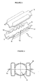
- This noise attenuation device is in the form of a section 1 of pipe integrable by each of its ends to the air intake circuit.
- One end of the pipe section 1 is an air inlet 2A while the other end is an air outlet 2B.
- the pipe section 1 has at each of its ends a section of reduced size to form a connection end solidarisable to the rest of the air intake circuit, preferably by sealing.
- the connection ends formed in one piece with the section 1 of pipe, extend at each end of the section 1 of driving beyond the shoulder formed by the narrowing of the section.
- This pipe section 1 is formed by the assembly of two half-shells shown at 3 and 4 in the figures.
- This pipe section 1 is partitioned longitudinally to define, along an axial air passage connecting the air inlet 2A and the outlet 2B of the pipe section 1, at least one blind volume consisting of a chamber 6 of resonance.
- This axial air passage is called the main duct section.
- This axial passageway can thus communicate, via at least one opening 7, with the blind volume constituting the resonance chamber 6 to establish an air communication between the resonance chamber 6 and the main duct section 5.
- each half-shell 3, 4 of the pipe section 1 is partitioned using at least one longitudinal partition 8, 9. This partition, shown at 8 for the half-shell 3 and 9 for the half-shell 4, came from molding with the half-shell.
- the bottom of the half-shell consists, seen in cross-section, of a concave portion corresponding to the zone serving to delimit the portion of the main section of conduit adjoined on each side by two bulges constituting the bottom portion of the chamber 6 delimited by means of said half-shell.
- other room profiles could have been adopted including a more regular scalloped profile.
- the realization of the bottom wall of each half-shell in the form of a multi-lobed wall makes it possible to increase the volume of the resonance chambers.
- the resonance volume delimited by the partitions 8, 9 longitudinals opposite the half-shells 3, 4 is compartmentalized through transverse walls 10, 11 integrally molded with each half-shell 3, 4.
- These transverse walls, shown at 10 for the half-shell 3 and 11 for the half-shell 4, extend, with their free edge 15, at least as far as in the joint plane of the half-shells.
- These transverse walls thus come by their free edge in bearing contact in the assembled state of the half-shells 3, 4 so as to delimit along the main section 5 of conduct a plurality of chambers 6 aligned Helmholtz resonator type allowing broadband attenuation of noise.
- each half-shell 3, or respectively 4 has two parallel longitudinal walls 8 or 9 arranged on either side of the main driving section so as to present two series of chambers 6 of FIG. resonance with the same or different acoustic characteristics.
- These resonance chambers 6 can thus have an increasing volume from the air inlet 2A towards the air outlet 2B of said pipe section 1.
- the spacing between the transverse walls 10 or respectively 11, on the one hand, the shape and the dimensions of the notches 14 of the longitudinal wall 8 or respectively 9 are chosen according to the frequency range of the noise to be attenuated .
- the transverse partition walls 10 and 11 of the half-shells 3, 4 are respectively connected to the longitudinal wall 8, 9 of said half-shell 3, 4, in the zone of said longitudinal wall 8, 9 extending between two notches 14, so as to form as many chambers 6 as notches 14.
- the noise attenuation device comprises, on either side of the main section 5 of conduct, each time a series of five chambers, a total of ten sounding chambers.
- Each chamber of a series of chambers is dimensioned differently, the chambers being identical from one series to another because the half-shells are, for reasons of simplification of manufacture, made identical.
- the two series of chambers are made symmetrical with respect to the median longitudinal plane of the driving section.
- each half-shell has along its longitudinal edges a flange whose outer face is intended to come into bearing contact with the outer face of the rim of the corresponding half-shell to form a joint plane 13 of the half-shells in the assembled state.
- the edges 12, 15 free in bearing contact of the longitudinal walls 8, 9 and transverse 10, 11 are joined to each other sealingly, preferably welded .
- the delimited chambers 6 do not communicate with each other. It could also have been provided in a similar manner to make notches in the transverse walls 10, 11 so as to ensure communication between the resonance chambers 6.
- the section reduction at each of the ends of the pipe section 1 to delimit connection ends securable to the rest of the air intake circuit allows to delimit a shoulder zone.
- the longitudinal walls 8, 9 for partitioning extend in the widened section portion of the pipe section 1 to the right of said shoulder.
Landscapes
- Engineering & Computer Science (AREA)
- Chemical & Material Sciences (AREA)
- Combustion & Propulsion (AREA)
- Mechanical Engineering (AREA)
- General Engineering & Computer Science (AREA)
- Manufacturing & Machinery (AREA)
- Exhaust Silencers (AREA)
- Exhaust Gas After Treatment (AREA)
- Supercharger (AREA)
- Cooling, Air Intake And Gas Exhaust, And Fuel Tank Arrangements In Propulsion Units (AREA)
- Air-Conditioning For Vehicles (AREA)
Claims (11)
- Vorrichtung zur Geräuschdämpfung in einem Lufteinlasskreis für vorzugsweise aufgeladene Verbrennungskraftmaschine oder Klimatisierungsgerät, wobei diese Geräusche vor allem vom Turbolader (2) und/oder vom Motor und/oder vom Klimatisierungsgerät des Fahrzeugs ausgehen, wobei sich diese Vorrichtung zum Dämpfen der Geräusche in Form eines an jedem seiner Enden integrierbaren Leitungsabschnitts (1) darstellt, der jeweils einen Eingang (2A) und einen Ausgang (2B) von Luft in den Lufteinlasskreis umfasst, wobei dieser Leitungsabschnitt (1), der aus der Montage von zwei Halbschalen (3, 4) hervorgegangen ist, längs geschlossen ist, um entlang eines axialen Luftdurchlasses, der den Lufteingang (2A) und den Luftausgang (2B) verbindet und als Leitungshauptabschnitt (5) bezeichnet wird, mindestens ein Blindvolumen zu begrenzen, das von einer Resonanzkammer (6) gebildet wird, die über mindestens eine Öffnung (7) mit dem Leitungshauptabschnitt (5) kommuniziert, um eine Luftkommunikation zwischen der Resonanzkammer (6) und dem Leitungshauptabschnitt (5) herzustellen,
dadurch gekennzeichnet, dass jede Halbschale (3, 4) des Leitungsabschnitts (1) mit Hilfe von mindestens einer Längstrennwand (8, 9) abgetrennt wird, die sich aus der Bodenwand der Halbschale (3, 4) entwickelt und sich mit ihrem freien Rand (12) bis zur Verbindungsebene (13) der Halbschalen (3, 4) erstreckt, wobei die Trennwände (8, 9) im montierten Zustand der Halbschalen (3, 4) durch ihren freien Rand (12) in punktuellen Abstützkontakt gelangen, wobei jede Trennwand (8, 9) auf ihrem freien Rand mit Kerben (14) ausgestattet ist, die im montierten Zustand der Halbschalen (3, 4) die Kommunikationsöffnung (7) zwischen Resonanzkammer (6) und Leitungshauptabschnitt (5) darstellen. - Vorrichtung zur Geräuschdämpfung nach Anspruch 1,
dadurch gekennzeichnet, dass das von den Längstrennwänden (8, 9) gegenüber den Halbschalen (3; 4) begrenzte Resonanzvolumen durch Querwände (10, 11) unterteilt ist, die mit jeder Halbschale (8, 9) mitgeformt wurden, wobei sich diese Querwände (10, 11) mit ihrem freien Rand mindestens bis zur Verbindungsebene der Halbschalen erstrecken, die im montierten Zustand der Halbschalen (3, 4) durch ihren freien Rand derart in Abstützkontakt gelangen, dass entlang des Leitungshauptabschnitts (5) eine Mehrzahl fluchtender Kammern (6) vom Typ Helmholtz-Resonator begrenzt werden, die das Dämpfen einer breiten Geräuschbandbreite erlauben. - Vorrichtung zur Geräuschdämpfung nach Anspruch 2,
dadurch gekennzeichnet, dass die Quertrennwände (10, 11) jeder Halbschale (3, 4) mit der Längswand (8, 9) der Halbschale (3, 4) im Bereich der Längswand (8, 9) verbunden sind, die sich zwischen zwei Kerben (14) erstreckt, so dass ebenso viele Kammern (6) gebildet werden wie Kerben (14). - Vorrichtung zur Geräuschdämpfung nach Anspruch 2,
dadurch gekennzeichnet, dass die freien Ränder (12, 15) in Abstützkontakt der Längs- (8, 9) und Querwände (10, 11) bei der Montage der Halbschalen (3, 4) miteinander dicht miteinander verbunden, vorzugsweise geschweißt, werden. - Vorrichtung zur Geräuschdämpfung nach den Ansprüchen 2 bis 4,
dadurch gekennzeichnet, dass die Resonanzkammern (6) vom Lufteingang (2A) in Richtung Luftausgang (2B) des Leitungsabschnitts (1) ein zunehmendes Volumen aufweisen. - Vorrichtung zur Geräuschdämpfung nach einem der Ansprüche 2 bis 5,
dadurch gekennzeichnet, dass der Abstand zwischen den Querwänden (10, 11) einerseits, die Form und die Abmessungen der Kerben (14) der Längswand (8, 9) andererseits in Abhängigkeit vom Frequenzbereich des zu dämpfenden Geräuschs ausgewählt sind. - Vorrichtung zur Geräuschdämpfung nach einem der Ansprüche 1 bis 6,
dadurch gekennzeichnet, dass die Halbschalen (3, 4) identisch sind. - Vorrichtung zur Geräuschdämpfung nach den Ansprüchen 1 bis 7,
dadurch gekennzeichnet, dass jede Halbschale (3, 4) zwei parallele Längswände (8, 9) umfasst, die auf der einen und der anderen Seite des Leitungshauptabschnitts (5) derart angeordnet sind, dass sie zwei Reihen Resonanzkammern (6) mit identischen oder unterschiedlichen Resonanzeigenschaften aufweisen. - Vorrichtung zur Geräuschdämpfung nach einem der Ansprüche 1 bis 8,
dadurch gekennzeichnet, dass der Leitungsabschnitt (1) an jedem seiner Enden einen Abschnitt reduzierter Abmessung aufweist, um einen Verbindungsstutzen darzustellen, der mit dem übrigen Lufteinlasskreis vorzugsweise durch dichtes Schweißen verbindbar ist. - Lufteinlasskreis für einen vorzugsweise aufgeladenen Motor oder Klimagerät der Bauart, die mit einer Vorrichtung zur Geräuschdämpfung ausgestattet ist, wobei diese Geräusche vor allem durch die Arbeit des Turboladers (2) und/oder des Motors und/oder des Klimatisierungsgeräts des Fahrzeugs verursacht werden, wobei sich diese Vorrichtung zum Dämpfen der Geräusche in Form eines an jedem seiner Enden integrierbaren Leitungsabschnitts (1) darstellt, der jeweils einen Eingang (2A) und einen Ausgang (2B) von Luft in den Lufteinlasskreis bildet, wobei dieser Leitungsabschnitt (1), der aus der Montage von zwei Halbschalen (3, 4) hervorgegangen ist, die längs geschlossen sind, um entlang eines axialen Luftdurchlasses, der den Lufteingang (2A) und den Luftausgang (2B) verbindet und als Leitungshauptabschnitt (5) bezeichnet wird, mindestens ein Blindvolumen zu begrenzen, das von einer Resonanzkammer (6) gebildet wird, die über mindestens eine Öffnung (7) mit dem Leitungshauptabschnitt (5) kommuniziert, um eine Luftkommunikation zwischen der Resonanzkammer (6) und dem Leitungshauptabschnitt (5) herzustellen,
dadurch gekennzeichnet, dass die Vorrichtung zur Geräuschdämpfung des Lufteinlasskreises einem der Ansprüche 1 bis 9 entspricht. - Lufteinlasskreis nach Anspruch 10,
dadurch gekennzeichnet, dass die Vorrichtung zur Geräuschdämpfung im Bereich des Lufteinlasskreises zwischen dem Turbolader (2) und einem Kühler (3) angeordnet ist, der imstand ist, die aus dem Turbolader (2) austretende Luft abzukühlen.
Applications Claiming Priority (2)
| Application Number | Priority Date | Filing Date | Title |
|---|---|---|---|
| FR0314828 | 2003-12-17 | ||
| FR0314828A FR2864168B1 (fr) | 2003-12-17 | 2003-12-17 | Dispositif d'attenuation des bruits sur un circuit d'admission d'air pour moteur a combustion interne ainsi que circuit d'admission d'air pour moteur equipe d'un tel dispositif d'attenuation des bruits |
Publications (3)
| Publication Number | Publication Date |
|---|---|
| EP1553284A1 EP1553284A1 (de) | 2005-07-13 |
| EP1553284B1 true EP1553284B1 (de) | 2011-02-16 |
| EP1553284B8 EP1553284B8 (de) | 2011-03-30 |
Family
ID=34586422
Family Applications (1)
| Application Number | Title | Priority Date | Filing Date |
|---|---|---|---|
| EP04292929A Expired - Lifetime EP1553284B8 (de) | 2003-12-17 | 2004-12-08 | Luftansaugdämpfungsanlage, insbesondere für aufgeladene Brennkraftmaschinen oder Klimaanlage, und Ansaugkanal mit solch einer Anlage |
Country Status (4)
| Country | Link |
|---|---|
| EP (1) | EP1553284B8 (de) |
| AT (1) | ATE498771T1 (de) |
| DE (1) | DE602004031404D1 (de) |
| FR (1) | FR2864168B1 (de) |
Families Citing this family (7)
| Publication number | Priority date | Publication date | Assignee | Title |
|---|---|---|---|---|
| FR2894644B1 (fr) | 2005-12-12 | 2009-04-03 | Trelleborg Fluid & Acoustic Solutions Tfas | Dispositif d'attenuation des bruits d'un circuit de circulation d'air, notamment pour moteur a combustion interne |
| FR2945839B1 (fr) * | 2009-05-20 | 2012-10-26 | Mann & Hummel Gmbh | Dispositif acoustique pour l'insonorisation de moteurs a combustion interne. |
| DE102010022780B4 (de) | 2010-06-04 | 2014-02-13 | Mann + Hummel Gmbh | Breitbanddämpfer |
| DE102011120148A1 (de) * | 2011-12-03 | 2013-06-06 | GM Global Technology Operations LLC (n. d. Gesetzen des Staates Delaware) | Schalldämpfer mit einem in einer Kreisbahneinführbaren Resonator-Einschubteil |
| DE102013201313A1 (de) | 2012-02-23 | 2013-08-29 | Ford Global Technologies, Llc | Wärmetauscher für eine Klimaanlage |
| DE202019106299U1 (de) * | 2019-11-12 | 2021-02-15 | Woco Industrietechnik Gmbh | Luftzuführleitung zur Kopplung an einen Luftverbraucher in einem Kraftfahrzeug, Anordnung zur Luftzuführung und Verwendung einer Luftzuführleitung |
| CN114753950B (zh) * | 2022-04-29 | 2025-09-30 | 平原滤清器有限公司 | 多腔体复合式降噪管路 |
Family Cites Families (6)
| Publication number | Priority date | Publication date | Assignee | Title |
|---|---|---|---|---|
| US5302783A (en) * | 1992-12-21 | 1994-04-12 | Abc Group | Resonator |
| JPH10187162A (ja) * | 1996-12-26 | 1998-07-14 | Inoac Corp | レゾネータ |
| DE19855708B4 (de) * | 1998-12-03 | 2009-04-30 | Denker, Dietrich, Prof. Dr.-Ing. | Rohrkammerdämpfer |
| DE10026355B4 (de) * | 2000-05-27 | 2010-06-17 | Mahle Filtersysteme Gmbh | Schalldämpfende Luftleitung |
| JP4453854B2 (ja) * | 2000-10-31 | 2010-04-21 | 株式会社イノアックコーポレーション | 車両用吸気ダクト |
| JP2004011604A (ja) * | 2002-06-11 | 2004-01-15 | Denso Corp | 内燃機関用吸気装置 |
-
2003
- 2003-12-17 FR FR0314828A patent/FR2864168B1/fr not_active Expired - Fee Related
-
2004
- 2004-12-08 DE DE602004031404T patent/DE602004031404D1/de not_active Expired - Lifetime
- 2004-12-08 EP EP04292929A patent/EP1553284B8/de not_active Expired - Lifetime
- 2004-12-08 AT AT04292929T patent/ATE498771T1/de not_active IP Right Cessation
Also Published As
| Publication number | Publication date |
|---|---|
| FR2864168A1 (fr) | 2005-06-24 |
| ATE498771T1 (de) | 2011-03-15 |
| FR2864168B1 (fr) | 2008-02-15 |
| DE602004031404D1 (de) | 2011-03-31 |
| EP1553284A1 (de) | 2005-07-13 |
| EP1553284B8 (de) | 2011-03-30 |
Similar Documents
| Publication | Publication Date | Title |
|---|---|---|
| EP2295782B1 (de) | Schalldämpfervorrichtung für eine Ansaugleitung eines thermischen Motors und Ansaugleitung mit eingebauter Schalldämpfervorrichtung | |
| EP2506907B1 (de) | Vorrichtung für geregelte gasabgabe, im besonderen für eine vorrichtung für unterstütztes atmen | |
| EP1553284B1 (de) | Luftansaugdämpfungsanlage, insbesondere für aufgeladene Brennkraftmaschinen oder Klimaanlage, und Ansaugkanal mit solch einer Anlage | |
| EP2106943B1 (de) | Leitung mit einer Kraftfahrzeugklimaanlagekühlkreisgeräuschdämmungsvorrichtung, und Kühlkreis umfassend einer solchen Leitung | |
| EP1433948B1 (de) | Luftansaugdämpfungsanlage | |
| EP3303815B1 (de) | Vorrichtung zur dämpfung von verbreiteten und abgestrahlten leitungsgeräuschen | |
| EP2101057B1 (de) | Vorrichtung zur Lärmreduzierung für Einspeiseleitung einer Wärmekraftmaschine und Einspeiseleitung, die diese Vorrichtung umfasst | |
| FR2840652A1 (fr) | Dispositif d'attenuation des bruits issus du fonctionnement du moteur a combustion interne et/ou du systeme de climatisation d'un vehicule | |
| EP1795733B1 (de) | Schalldämpfer zur Verringerung von Luftgeräuschen, insbesondre für interne Brennkraftmaschinen | |
| CA2761601C (fr) | Turbomoteur comportant un cone de guidage des gaz d'echappement avec un attenuateur sonore | |
| FR3076318A1 (fr) | Dispositif de génération de son et système d’échappement de véhicule | |
| FR2946120A1 (fr) | Dispositif d'attenuation acoustique pour ligne d'admission d'un moteur thermique,et ligne d'admission l'incorporant. | |
| EP2429843B1 (de) | Kraftfahrzeugklimaanlagenzyklus mit volumenexpansionskammer | |
| FR2871547A1 (fr) | Dispositif d'attenuation du bruit de gaz dans un conduit, notamment pour vehicule automobile | |
| FR2875560A1 (fr) | Ventilateur centrifuge a bruit reduit pour systeme de ventilation d'un vehicule automobile | |
| FR2901738A1 (fr) | Dispositif reducteur de bruit pour circuit de climatisation de vehicule automobile, conduite et ce circuit l'incorporant | |
| EP1712382B1 (de) | Geräuschgedämpfte Belüftungseinrichtung für ein Kraftfahrzeug | |
| FR2840653A1 (fr) | Dispositif d'attenuation des bruits sur un circuit d'admission d'air pour moteur de preference suralimente ou appareil de climatisation et circuit d'admission equipe d'un tel dispositif | |
| FR2937686A1 (fr) | Moteur thermique turbocompresse comportant un circuit d'air simplifie | |
| EP2354524B1 (de) | Vorrichtung zur akkustischen Dämpfung für eine Ansaugleitung eines thermischen Motors, flexibles Rohr und Ansaugleitung umfassend eine solche Vorrichtung | |
| FR2892344A1 (fr) | Dispositif de ventilation d'un vehicule automobile comportant des moyens d'attenuation de bruit | |
| FR2925611A3 (fr) | Resonateur acoustique de filtre a air de vehicule automobile | |
| FR2643677A1 (fr) | Silencieux pour un systeme d'echappement d'un vehicule | |
| FR2894645A1 (fr) | Conduit de transport de gaz ayant un ecoulement a pression variable avec attenuation acoustique integree |
Legal Events
| Date | Code | Title | Description |
|---|---|---|---|
| PUAI | Public reference made under article 153(3) epc to a published international application that has entered the european phase |
Free format text: ORIGINAL CODE: 0009012 |
|
| AK | Designated contracting states |
Kind code of ref document: A1 Designated state(s): AT BE BG CH CY CZ DE DK EE ES FI FR GB GR HU IE IS IT LI LT LU MC NL PL PT RO SE SI SK TR |
|
| AX | Request for extension of the european patent |
Extension state: AL BA HR LV MK YU |
|
| 17P | Request for examination filed |
Effective date: 20051013 |
|
| AKX | Designation fees paid |
Designated state(s): AT BE BG CH CY CZ DE DK EE ES FI FR GB GR HU IE IS IT LI LT LU MC NL PL PT RO SE SI SK TR |
|
| RAP1 | Party data changed (applicant data changed or rights of an application transferred) |
Owner name: TRELLEBORG FLUID & ACOUSTIC SOLUTIONS (TFAS) |
|
| GRAP | Despatch of communication of intention to grant a patent |
Free format text: ORIGINAL CODE: EPIDOSNIGR1 |
|
| GRAS | Grant fee paid |
Free format text: ORIGINAL CODE: EPIDOSNIGR3 |
|
| GRAA | (expected) grant |
Free format text: ORIGINAL CODE: 0009210 |
|
| AK | Designated contracting states |
Kind code of ref document: B1 Designated state(s): AT BE BG CH CY CZ DE DK EE ES FI FR GB GR HU IE IS IT LI LT LU MC NL PL PT RO SE SI SK TR |
|
| REG | Reference to a national code |
Ref country code: GB Ref legal event code: FG4D Free format text: NOT ENGLISH |
|
| REG | Reference to a national code |
Ref country code: CH Ref legal event code: EP |
|
| RAP2 | Party data changed (patent owner data changed or rights of a patent transferred) |
Owner name: TRISTONE FLOWTECH SOLUTIONS (TFS) |
|
| REG | Reference to a national code |
Ref country code: IE Ref legal event code: FG4D Free format text: LANGUAGE OF EP DOCUMENT: FRENCH |
|
| REF | Corresponds to: |
Ref document number: 602004031404 Country of ref document: DE Date of ref document: 20110331 Kind code of ref document: P |
|
| REG | Reference to a national code |
Ref country code: DE Ref legal event code: R096 Ref document number: 602004031404 Country of ref document: DE Effective date: 20110331 |
|
| REG | Reference to a national code |
Ref country code: DE Ref legal event code: R081 Ref document number: 602004031404 Country of ref document: DE Owner name: TRISTONE FLOWTECH SOLUTIONS (TFS), FR Free format text: FORMER OWNER: TRELLEBORG FLUID & ACOUSTIC SOLUTIONS (TFAS), CARQUEFOU, FR Effective date: 20110215 |
|
| REG | Reference to a national code |
Ref country code: NL Ref legal event code: VDEP Effective date: 20110216 |
|
| LTIE | Lt: invalidation of european patent or patent extension |
Effective date: 20110216 |
|
| PG25 | Lapsed in a contracting state [announced via postgrant information from national office to epo] |
Ref country code: GR Free format text: LAPSE BECAUSE OF FAILURE TO SUBMIT A TRANSLATION OF THE DESCRIPTION OR TO PAY THE FEE WITHIN THE PRESCRIBED TIME-LIMIT Effective date: 20110517 Ref country code: ES Free format text: LAPSE BECAUSE OF FAILURE TO SUBMIT A TRANSLATION OF THE DESCRIPTION OR TO PAY THE FEE WITHIN THE PRESCRIBED TIME-LIMIT Effective date: 20110527 Ref country code: LT Free format text: LAPSE BECAUSE OF FAILURE TO SUBMIT A TRANSLATION OF THE DESCRIPTION OR TO PAY THE FEE WITHIN THE PRESCRIBED TIME-LIMIT Effective date: 20110216 Ref country code: PT Free format text: LAPSE BECAUSE OF FAILURE TO SUBMIT A TRANSLATION OF THE DESCRIPTION OR TO PAY THE FEE WITHIN THE PRESCRIBED TIME-LIMIT Effective date: 20110616 Ref country code: SE Free format text: LAPSE BECAUSE OF FAILURE TO SUBMIT A TRANSLATION OF THE DESCRIPTION OR TO PAY THE FEE WITHIN THE PRESCRIBED TIME-LIMIT Effective date: 20110216 |
|
| PG25 | Lapsed in a contracting state [announced via postgrant information from national office to epo] |
Ref country code: BG Free format text: LAPSE BECAUSE OF FAILURE TO SUBMIT A TRANSLATION OF THE DESCRIPTION OR TO PAY THE FEE WITHIN THE PRESCRIBED TIME-LIMIT Effective date: 20110516 Ref country code: NL Free format text: LAPSE BECAUSE OF FAILURE TO SUBMIT A TRANSLATION OF THE DESCRIPTION OR TO PAY THE FEE WITHIN THE PRESCRIBED TIME-LIMIT Effective date: 20110216 Ref country code: CY Free format text: LAPSE BECAUSE OF FAILURE TO SUBMIT A TRANSLATION OF THE DESCRIPTION OR TO PAY THE FEE WITHIN THE PRESCRIBED TIME-LIMIT Effective date: 20110216 Ref country code: FI Free format text: LAPSE BECAUSE OF FAILURE TO SUBMIT A TRANSLATION OF THE DESCRIPTION OR TO PAY THE FEE WITHIN THE PRESCRIBED TIME-LIMIT Effective date: 20110216 Ref country code: SI Free format text: LAPSE BECAUSE OF FAILURE TO SUBMIT A TRANSLATION OF THE DESCRIPTION OR TO PAY THE FEE WITHIN THE PRESCRIBED TIME-LIMIT Effective date: 20110216 Ref country code: PL Free format text: LAPSE BECAUSE OF FAILURE TO SUBMIT A TRANSLATION OF THE DESCRIPTION OR TO PAY THE FEE WITHIN THE PRESCRIBED TIME-LIMIT Effective date: 20110216 Ref country code: AT Free format text: LAPSE BECAUSE OF FAILURE TO SUBMIT A TRANSLATION OF THE DESCRIPTION OR TO PAY THE FEE WITHIN THE PRESCRIBED TIME-LIMIT Effective date: 20110216 |
|
| REG | Reference to a national code |
Ref country code: IE Ref legal event code: FD4D |
|
| PG25 | Lapsed in a contracting state [announced via postgrant information from national office to epo] |
Ref country code: DK Free format text: LAPSE BECAUSE OF FAILURE TO SUBMIT A TRANSLATION OF THE DESCRIPTION OR TO PAY THE FEE WITHIN THE PRESCRIBED TIME-LIMIT Effective date: 20110216 Ref country code: IE Free format text: LAPSE BECAUSE OF FAILURE TO SUBMIT A TRANSLATION OF THE DESCRIPTION OR TO PAY THE FEE WITHIN THE PRESCRIBED TIME-LIMIT Effective date: 20110216 Ref country code: EE Free format text: LAPSE BECAUSE OF FAILURE TO SUBMIT A TRANSLATION OF THE DESCRIPTION OR TO PAY THE FEE WITHIN THE PRESCRIBED TIME-LIMIT Effective date: 20110216 |
|
| PG25 | Lapsed in a contracting state [announced via postgrant information from national office to epo] |
Ref country code: RO Free format text: LAPSE BECAUSE OF FAILURE TO SUBMIT A TRANSLATION OF THE DESCRIPTION OR TO PAY THE FEE WITHIN THE PRESCRIBED TIME-LIMIT Effective date: 20110216 Ref country code: SK Free format text: LAPSE BECAUSE OF FAILURE TO SUBMIT A TRANSLATION OF THE DESCRIPTION OR TO PAY THE FEE WITHIN THE PRESCRIBED TIME-LIMIT Effective date: 20110216 Ref country code: CZ Free format text: LAPSE BECAUSE OF FAILURE TO SUBMIT A TRANSLATION OF THE DESCRIPTION OR TO PAY THE FEE WITHIN THE PRESCRIBED TIME-LIMIT Effective date: 20110216 |
|
| PLBE | No opposition filed within time limit |
Free format text: ORIGINAL CODE: 0009261 |
|
| STAA | Information on the status of an ep patent application or granted ep patent |
Free format text: STATUS: NO OPPOSITION FILED WITHIN TIME LIMIT |
|
| 26N | No opposition filed |
Effective date: 20111117 |
|
| REG | Reference to a national code |
Ref country code: DE Ref legal event code: R097 Ref document number: 602004031404 Country of ref document: DE Effective date: 20111117 |
|
| PG25 | Lapsed in a contracting state [announced via postgrant information from national office to epo] |
Ref country code: IT Free format text: LAPSE BECAUSE OF FAILURE TO SUBMIT A TRANSLATION OF THE DESCRIPTION OR TO PAY THE FEE WITHIN THE PRESCRIBED TIME-LIMIT Effective date: 20110216 |
|
| PGFP | Annual fee paid to national office [announced via postgrant information from national office to epo] |
Ref country code: DE Payment date: 20111222 Year of fee payment: 8 |
|
| BERE | Be: lapsed |
Owner name: TRELLEBORG FLUID & ACOUSTIC SOLUTIONS (TFAS) Effective date: 20111231 |
|
| PG25 | Lapsed in a contracting state [announced via postgrant information from national office to epo] |
Ref country code: MC Free format text: LAPSE BECAUSE OF NON-PAYMENT OF DUE FEES Effective date: 20111231 |
|
| REG | Reference to a national code |
Ref country code: CH Ref legal event code: PL |
|
| PG25 | Lapsed in a contracting state [announced via postgrant information from national office to epo] |
Ref country code: LI Free format text: LAPSE BECAUSE OF NON-PAYMENT OF DUE FEES Effective date: 20111231 Ref country code: BE Free format text: LAPSE BECAUSE OF NON-PAYMENT OF DUE FEES Effective date: 20111231 Ref country code: CH Free format text: LAPSE BECAUSE OF NON-PAYMENT OF DUE FEES Effective date: 20111231 |
|
| PG25 | Lapsed in a contracting state [announced via postgrant information from national office to epo] |
Ref country code: LU Free format text: LAPSE BECAUSE OF NON-PAYMENT OF DUE FEES Effective date: 20111208 |
|
| PG25 | Lapsed in a contracting state [announced via postgrant information from national office to epo] |
Ref country code: IS Free format text: LAPSE BECAUSE OF FAILURE TO SUBMIT A TRANSLATION OF THE DESCRIPTION OR TO PAY THE FEE WITHIN THE PRESCRIBED TIME-LIMIT Effective date: 20110216 |
|
| GBPC | Gb: european patent ceased through non-payment of renewal fee |
Effective date: 20121208 |
|
| PG25 | Lapsed in a contracting state [announced via postgrant information from national office to epo] |
Ref country code: TR Free format text: LAPSE BECAUSE OF FAILURE TO SUBMIT A TRANSLATION OF THE DESCRIPTION OR TO PAY THE FEE WITHIN THE PRESCRIBED TIME-LIMIT Effective date: 20110216 |
|
| REG | Reference to a national code |
Ref country code: DE Ref legal event code: R119 Ref document number: 602004031404 Country of ref document: DE Effective date: 20130702 |
|
| PG25 | Lapsed in a contracting state [announced via postgrant information from national office to epo] |
Ref country code: DE Free format text: LAPSE BECAUSE OF NON-PAYMENT OF DUE FEES Effective date: 20130702 Ref country code: HU Free format text: LAPSE BECAUSE OF FAILURE TO SUBMIT A TRANSLATION OF THE DESCRIPTION OR TO PAY THE FEE WITHIN THE PRESCRIBED TIME-LIMIT Effective date: 20110216 |
|
| PG25 | Lapsed in a contracting state [announced via postgrant information from national office to epo] |
Ref country code: GB Free format text: LAPSE BECAUSE OF NON-PAYMENT OF DUE FEES Effective date: 20121208 |
|
| REG | Reference to a national code |
Ref country code: FR Ref legal event code: PLFP Year of fee payment: 12 |
|
| REG | Reference to a national code |
Ref country code: FR Ref legal event code: PLFP Year of fee payment: 13 |
|
| REG | Reference to a national code |
Ref country code: FR Ref legal event code: PLFP Year of fee payment: 14 |
|
| PGFP | Annual fee paid to national office [announced via postgrant information from national office to epo] |
Ref country code: FR Payment date: 20191219 Year of fee payment: 16 |
|
| PG25 | Lapsed in a contracting state [announced via postgrant information from national office to epo] |
Ref country code: FR Free format text: LAPSE BECAUSE OF NON-PAYMENT OF DUE FEES Effective date: 20201231 |