EP1553284B1 - Air intake silencing device especially for turbocharged engines or air conditioner and intake circuit with such a device - Google Patents
Air intake silencing device especially for turbocharged engines or air conditioner and intake circuit with such a device Download PDFInfo
- Publication number
- EP1553284B1 EP1553284B1 EP04292929A EP04292929A EP1553284B1 EP 1553284 B1 EP1553284 B1 EP 1553284B1 EP 04292929 A EP04292929 A EP 04292929A EP 04292929 A EP04292929 A EP 04292929A EP 1553284 B1 EP1553284 B1 EP 1553284B1
- Authority
- EP
- European Patent Office
- Prior art keywords
- air
- shells
- conduit section
- noises
- attenuating
- Prior art date
- Legal status (The legal status is an assumption and is not a legal conclusion. Google has not performed a legal analysis and makes no representation as to the accuracy of the status listed.)
- Not-in-force
Links
- 230000030279 gene silencing Effects 0.000 title 1
- 238000005192 partition Methods 0.000 claims abstract description 18
- 238000004378 air conditioning Methods 0.000 claims abstract description 13
- 238000004891 communication Methods 0.000 claims abstract description 13
- 238000002485 combustion reaction Methods 0.000 claims abstract description 6
- 230000002238 attenuated effect Effects 0.000 claims description 3
- 238000000465 moulding Methods 0.000 claims description 2
- 238000000638 solvent extraction Methods 0.000 claims description 2
- 238000001816 cooling Methods 0.000 claims 1
- 238000003466 welding Methods 0.000 claims 1
- 238000007789 sealing Methods 0.000 abstract description 2
- 239000012535 impurity Substances 0.000 description 2
- 238000012986 modification Methods 0.000 description 2
- 230000004048 modification Effects 0.000 description 2
- 238000004140 cleaning Methods 0.000 description 1
- 238000005520 cutting process Methods 0.000 description 1
- 230000010354 integration Effects 0.000 description 1
- 238000004519 manufacturing process Methods 0.000 description 1
- 239000002184 metal Substances 0.000 description 1
- 238000000034 method Methods 0.000 description 1
- 229920001296 polysiloxane Polymers 0.000 description 1
- 238000011084 recovery Methods 0.000 description 1
Images


Classifications
-
- F—MECHANICAL ENGINEERING; LIGHTING; HEATING; WEAPONS; BLASTING
- F02—COMBUSTION ENGINES; HOT-GAS OR COMBUSTION-PRODUCT ENGINE PLANTS
- F02M—SUPPLYING COMBUSTION ENGINES IN GENERAL WITH COMBUSTIBLE MIXTURES OR CONSTITUENTS THEREOF
- F02M35/00—Combustion-air cleaners, air intakes, intake silencers, or induction systems specially adapted for, or arranged on, internal-combustion engines
- F02M35/12—Intake silencers ; Sound modulation, transmission or amplification
- F02M35/1205—Flow throttling or guiding
- F02M35/1216—Flow throttling or guiding by using a plurality of holes, slits, protrusions, perforations, ribs or the like; Surface structures; Turbulence generators
-
- F—MECHANICAL ENGINEERING; LIGHTING; HEATING; WEAPONS; BLASTING
- F02—COMBUSTION ENGINES; HOT-GAS OR COMBUSTION-PRODUCT ENGINE PLANTS
- F02M—SUPPLYING COMBUSTION ENGINES IN GENERAL WITH COMBUSTIBLE MIXTURES OR CONSTITUENTS THEREOF
- F02M35/00—Combustion-air cleaners, air intakes, intake silencers, or induction systems specially adapted for, or arranged on, internal-combustion engines
- F02M35/12—Intake silencers ; Sound modulation, transmission or amplification
- F02M35/1255—Intake silencers ; Sound modulation, transmission or amplification using resonance
- F02M35/1261—Helmholtz resonators
-
- F—MECHANICAL ENGINEERING; LIGHTING; HEATING; WEAPONS; BLASTING
- F02—COMBUSTION ENGINES; HOT-GAS OR COMBUSTION-PRODUCT ENGINE PLANTS
- F02M—SUPPLYING COMBUSTION ENGINES IN GENERAL WITH COMBUSTIBLE MIXTURES OR CONSTITUENTS THEREOF
- F02M35/00—Combustion-air cleaners, air intakes, intake silencers, or induction systems specially adapted for, or arranged on, internal-combustion engines
- F02M35/12—Intake silencers ; Sound modulation, transmission or amplification
- F02M35/1255—Intake silencers ; Sound modulation, transmission or amplification using resonance
- F02M35/1266—Intake silencers ; Sound modulation, transmission or amplification using resonance comprising multiple chambers or compartments
-
- F—MECHANICAL ENGINEERING; LIGHTING; HEATING; WEAPONS; BLASTING
- F02—COMBUSTION ENGINES; HOT-GAS OR COMBUSTION-PRODUCT ENGINE PLANTS
- F02M—SUPPLYING COMBUSTION ENGINES IN GENERAL WITH COMBUSTIBLE MIXTURES OR CONSTITUENTS THEREOF
- F02M35/00—Combustion-air cleaners, air intakes, intake silencers, or induction systems specially adapted for, or arranged on, internal-combustion engines
- F02M35/12—Intake silencers ; Sound modulation, transmission or amplification
- F02M35/1283—Manufacturing or assembly; Connectors; Fixations
Definitions
- the present invention relates to a device for attenuating noise on an air intake circuit for an internal combustion engine, preferably supercharged, or apparatus for air conditioning, and an air intake circuit for an engine, preferably supercharged, or air conditioning apparatus, equipped with such a device for attenuation of noise.
- a noise attenuation device in the form of a pipe section integrable by each of its ends respectively constituting an inlet and an air outlet to the air intake circuit, this section of pipe , formed by the assembly of two half-shells, being partitioned longitudinally to delimit, along an axial air passage connecting the air inlet and the air outlet and called the main duct section, at least a blind volume consisting of a resonance chamber communicating via at least one opening with said main duct section to establish an air communication between the resonance chamber and the main duct section.
- a noise attenuation device in the form of a pipe section integrable by each of its ends respectively constituting an inlet and an air outlet to the air intake circuit, this section of pipe , formed by the assembly of two half-shells, being partitioned longitudinally to delimit, along an axial air passage connecting the air inlet and the air outlet and called the main duct section, at least a blind volume consisting of a resonance chamber communicating via at least one opening with said main duct section to establish an air communication between
- Such a noise attenuation device is more particularly intended to be positioned on the supercharged portion of an air intake circuit for an internal combustion engine.
- a turbocharger This increases the air supply pressure but also the temperature. It is therefore necessary, as illustrated by figure 1 relating to the state of the art, that the air passes through a cooler A fixed on the vehicle before reaching the engine.
- the line connecting the turbocharger B and the air cooler A is composed of two parts, namely a flexible portion C rubber or silicone adapted to absorb the movements of the engine / body and a rigid portion D plastic or metal to minimize the cost and mass of all.
- This noise attenuation device is formed of two elements which, in the assembled state, form a double-walled cylinder. The two parts of this cylinder are obtained by cutting the cylinder along its median diametral plane. Each half-cylinder consists of two walls connected to each other by their edge to define a closed volume. This volume closed by an opening in each inner wall communicates with the axial pipe section formed in the assembled state of the two cylinder parts.
- the resonance chambers thus obtained are annular chambers. Because of the design of the attenuation device, these annular chambers are at most two in number. As a result, the system obtained is an extremely rigid system where it becomes very difficult to vary the frequency setting of the resonance chambers obtained and the general shape of the conduit.
- an air cleaning device intended more particularly to be positioned between the mouth or external air intake of the air intake circuit and the filter box on the part of the air intake circuit in which the air flowing is an air generally charged with impurities.
- This device is not intended to reduce noise. It is simply not to increase the sound level.
- This device is again constituted by the assembly of two half-shells. Each half-shell is provided with partitions which define an axial duct connecting an inlet and an air outlet, these partitions being interrupted over their entire height to define a single opening of communication between the impurity recovery chambers and the axial duct, these chambers being made asymmetrical. In view of the purpose of this device, this device must be considered as belonging to the technical background.
- this opening is obtained by an interruption of the partition, this opening can vary in size only in its width. As a result, the possibilities of modifications of the opening are limited. Moreover, this design is such that it is possible to integrate, in such a device, only two asymmetrical chambers.
- An object of the present invention is therefore to provide a noise attenuation device on an air intake circuit whose design allows attenuation of noise in a wide frequency band while having a small footprint.
- Another object of the present invention is to propose a device for attenuating noise on an air intake circuit whose design makes it possible to have an acoustic attenuator incorporated in a rigid part of pipe in order to minimize the number of components.
- Another object of the present invention is to provide a noise attenuation device on an air intake circuit whose design makes it possible to adapt to complex driving profiles.
- Another object of the present invention is to provide a noise attenuation device on an air intake circuit whose design allows to make easily varying the openings for communicating the resonance chambers with the main pipe section by varying the height, width, shape and position of the openings on said conduit so as to vary will frequency setting resonators thus formed.
- the subject of the invention is a device for attenuating noise on an air intake circuit for an internal combustion engine, preferably supercharged, or an apparatus for air conditioning, these noises being in particular derived from the turbocharger and / or the engine and / or the vehicle air conditioning unit, this noise attenuation device being in the form of a section of pipe integrable by each of its ends respectively constituting an inlet and an air outlet to the circuit air intake, this section of pipe, resulting from the assembly of two half-shells, being partitioned longitudinally to delimit, along an axial air passage connecting the air inlet and the outlet of and called main conduit section, at least one blind volume consisting of a resonance chamber communicating via at least one opening with said main duct section to establish a communication of a ir between the resonance chamber and the main duct section, characterized in that each half-shell of the duct section is partitioned by means of at least one longitudinal partition originating on the bottom wall of the half-shell.
- each partition coming into point contact point by their free edge in the assembled state of the half-shells, each partition being provided on its edge free of notches constituting, in the assembled state of the half-shells, the communication opening between the resonance chamber and the main duct section.
- the design of the attenuation device it is possible to integrate such a device on any type of circuit, including circuits with a complex profile.
- a noise attenuation device makes it possible to simultaneously perform the rigid duct air circulation and acoustic attenuation function by means of a single element whose profile can be any. This objective could not be fulfilled with conventional noise attenuation devices with annular chambers.
- the subject of the invention is also an air intake circuit for an engine, preferably a supercharged engine, or an air conditioning apparatus, of the type equipped with a device for attenuation of the noises, these noises being in particular stemming from the operation of the turbocompressor and or the engine and / or the vehicle air conditioning unit, this noise attenuation device being in the form of a section of pipe integrable by each of its ends constituting an inlet and an air outlet to the circuit air intake, this section of pipe, resulting from the assembly of two half-shells, being partitioned longitudinally to delimit, along an axial air passage connecting the air inlet and the outlet of and called a main duct section, at least one blind volume consisting of a resonance chamber communicating via at least one opening with said main duct section for establishing an air communication between the resonance chamber and the main duct section, characterized in that the noise attenuation device of the air intake circuit is of the aforementioned type.
- the noise attenuation device object of the invention, is intended to be installed on an air intake circuit for an internal combustion engine, preferably supercharged, or on a circuit of air intake for an air conditioning unit.
- the noises to be attenuated are in particular those from the turbocharger 2 and / or the engine and / or the air conditioning device of the vehicle.
- the noise attenuation device is disposed in the area of the air intake circuit extending between the turbocharger 2 and a cooler 3 adapted to cool the air from the turbocharger 2. This preferred arrangement allows to combine in a single element noise attenuation functions and rigid air circulation pipe which, until now, were made in the form of two differentiated elements.
- This noise attenuation device is in the form of a section 1 of pipe integrable by each of its ends to the air intake circuit.
- One end of the pipe section 1 is an air inlet 2A while the other end is an air outlet 2B.
- the pipe section 1 has at each of its ends a section of reduced size to form a connection end solidarisable to the rest of the air intake circuit, preferably by sealing.
- the connection ends formed in one piece with the section 1 of pipe, extend at each end of the section 1 of driving beyond the shoulder formed by the narrowing of the section.
- This pipe section 1 is formed by the assembly of two half-shells shown at 3 and 4 in the figures.
- This pipe section 1 is partitioned longitudinally to define, along an axial air passage connecting the air inlet 2A and the outlet 2B of the pipe section 1, at least one blind volume consisting of a chamber 6 of resonance.
- This axial air passage is called the main duct section.
- This axial passageway can thus communicate, via at least one opening 7, with the blind volume constituting the resonance chamber 6 to establish an air communication between the resonance chamber 6 and the main duct section 5.
- each half-shell 3, 4 of the pipe section 1 is partitioned using at least one longitudinal partition 8, 9. This partition, shown at 8 for the half-shell 3 and 9 for the half-shell 4, came from molding with the half-shell.
- the bottom of the half-shell consists, seen in cross-section, of a concave portion corresponding to the zone serving to delimit the portion of the main section of conduit adjoined on each side by two bulges constituting the bottom portion of the chamber 6 delimited by means of said half-shell.
- other room profiles could have been adopted including a more regular scalloped profile.
- the realization of the bottom wall of each half-shell in the form of a multi-lobed wall makes it possible to increase the volume of the resonance chambers.
- the resonance volume delimited by the partitions 8, 9 longitudinals opposite the half-shells 3, 4 is compartmentalized through transverse walls 10, 11 integrally molded with each half-shell 3, 4.
- These transverse walls, shown at 10 for the half-shell 3 and 11 for the half-shell 4, extend, with their free edge 15, at least as far as in the joint plane of the half-shells.
- These transverse walls thus come by their free edge in bearing contact in the assembled state of the half-shells 3, 4 so as to delimit along the main section 5 of conduct a plurality of chambers 6 aligned Helmholtz resonator type allowing broadband attenuation of noise.
- each half-shell 3, or respectively 4 has two parallel longitudinal walls 8 or 9 arranged on either side of the main driving section so as to present two series of chambers 6 of FIG. resonance with the same or different acoustic characteristics.
- These resonance chambers 6 can thus have an increasing volume from the air inlet 2A towards the air outlet 2B of said pipe section 1.
- the spacing between the transverse walls 10 or respectively 11, on the one hand, the shape and the dimensions of the notches 14 of the longitudinal wall 8 or respectively 9 are chosen according to the frequency range of the noise to be attenuated .
- the transverse partition walls 10 and 11 of the half-shells 3, 4 are respectively connected to the longitudinal wall 8, 9 of said half-shell 3, 4, in the zone of said longitudinal wall 8, 9 extending between two notches 14, so as to form as many chambers 6 as notches 14.
- the noise attenuation device comprises, on either side of the main section 5 of conduct, each time a series of five chambers, a total of ten sounding chambers.
- Each chamber of a series of chambers is dimensioned differently, the chambers being identical from one series to another because the half-shells are, for reasons of simplification of manufacture, made identical.
- the two series of chambers are made symmetrical with respect to the median longitudinal plane of the driving section.
- each half-shell has along its longitudinal edges a flange whose outer face is intended to come into bearing contact with the outer face of the rim of the corresponding half-shell to form a joint plane 13 of the half-shells in the assembled state.
- the edges 12, 15 free in bearing contact of the longitudinal walls 8, 9 and transverse 10, 11 are joined to each other sealingly, preferably welded .
- the delimited chambers 6 do not communicate with each other. It could also have been provided in a similar manner to make notches in the transverse walls 10, 11 so as to ensure communication between the resonance chambers 6.
- the section reduction at each of the ends of the pipe section 1 to delimit connection ends securable to the rest of the air intake circuit allows to delimit a shoulder zone.
- the longitudinal walls 8, 9 for partitioning extend in the widened section portion of the pipe section 1 to the right of said shoulder.
Abstract
Description
La présente invention concerne un dispositif d'atténuation des bruits sur un circuit d'admission d'air pour moteur à combustion interne, de préférence suralimenté, ou appareil pour climatisation, ainsi qu'un circuit d'admission d'air pour moteur, de préférence suralimenté, ou appareil de climatisation, équipé d'un tel dispositif d'atténuation des bruits.The present invention relates to a device for attenuating noise on an air intake circuit for an internal combustion engine, preferably supercharged, or apparatus for air conditioning, and an air intake circuit for an engine, preferably supercharged, or air conditioning apparatus, equipped with such a device for attenuation of noise.
Elle concerne plus particulièrement un dispositif d'atténuation des bruits se présentant sous forme d'une section de conduite intégrable par chacune de ses extrémités constituant respectivement une entrée et une sortie d'air au circuit d'admission d'air, cette section de conduite, formée par l'assemblage de deux demi-coquilles, étant cloisonnée longitudinalement pour délimiter, le long d'un passage d'air axial reliant l'entrée d'air et la sortie d'air et appelé section principale de conduit, au moins un volume borgne constitué d'une chambre de résonance communiquant par l'intermédiaire d'au moins une ouverture avec ladite section principale de conduit pour établir une communication d'air entre la chambre de résonance et la section principale de conduit.Un exemple d'un tel dispositif est décrit dans le document
Un tel dispositif d'atténuation des bruits est plus particulièrement destiné à être positionné sur la partie suralimentée d'un circuit d'admission d'air pour moteur à combustion interne. En effet, pour augmenter la puissance des moteurs, on utilise aujourd'hui un turbocompresseur. Celui-ci augmente la pression d'alimentation d'air mais également la température. Il est donc nécessaire, comme l'illustre la
Une deuxième problématique, liée au sifflement du turbocompresseur A, intervient sur cette conduite. En effet, le turbocompresseur A génère un sifflement dont la fréquence est proportionnelle à la vitesse de rotation de la turbine. Cette onde acoustique va se propager dans la conduite et rayonner à travers la partie C souple. Afin d'atténuer ces bruits, la solution retenue jusqu'ici est d'implanter un amortisseur E le plus près possible du turbocompresseur B comme l'illustre la
Un grand nombre de dispositifs d'atténuation des bruits sont connus à travers l'état de la technique. Ainsi, un exemple de dispositif d'atténuation des bruits est notamment décrit dans le
On connaît également, à travers le
Un but de la présente invention est donc de proposer un dispositif d'atténuation des bruits sur un circuit d'admission d'air dont la conception permet une atténuation des bruits dans une large bande de fréquences tout en présentant un encombrement réduit.An object of the present invention is therefore to provide a noise attenuation device on an air intake circuit whose design allows attenuation of noise in a wide frequency band while having a small footprint.
Un autre but de la présente invention est de proposer un dispositif d'atténuation des bruits sur un circuit d'admission d'air dont la conception permet de disposer d'un atténuateur acoustique incorporé à une partie rigide de conduite afin de minimiser le nombre de composants.Another object of the present invention is to propose a device for attenuating noise on an air intake circuit whose design makes it possible to have an acoustic attenuator incorporated in a rigid part of pipe in order to minimize the number of components.
Un autre but de la présente invention est de proposer un dispositif d'atténuation des bruits sur un circuit d'admission d'air dont la conception permet de s'adapter à des profils complexes de conduite.Another object of the present invention is to provide a noise attenuation device on an air intake circuit whose design makes it possible to adapt to complex driving profiles.
Un autre but de la présente invention est de proposer un dispositif d'atténuation des bruits sur un circuit d'admission d'air dont la conception permet de faire varier, de manière aisée, les ouvertures servant à la communication des chambres de résonance avec la section de conduite principale par modification de la hauteur, de la largeur, de la forme et de la position des ouvertures sur ledit conduit de manière à faire varier à volonté le calage en fréquence des résonateurs ainsi formés.Another object of the present invention is to provide a noise attenuation device on an air intake circuit whose design allows to make easily varying the openings for communicating the resonance chambers with the main pipe section by varying the height, width, shape and position of the openings on said conduit so as to vary will frequency setting resonators thus formed.
A cet effet, l'invention a pour objet un dispositif d'atténuation des bruits sur un circuit d'admission d'air pour moteur à combustion interne, de préférence suralimenté, ou appareil pour climatisation, ces bruits étant notamment issus du turbocompresseur et/ou du moteur et/ou de l'appareil de climatisation du véhicule, ce dispositif d'atténuation des bruits se présentant sous forme d'une section de conduite intégrable par chacune de ses extrémités constituant respectivement une entrée et une sortie d'air au circuit d'admission d'air, cette section de conduite, issue de l'assemblage de deux demi-coquilles, étant cloisonnée longitudinalement pour délimiter, le long d'un passage d'air axial reliant l'entrée d'air et la sortie d'air et appelé section principale de conduit, au moins un volume borgne constitué d'une chambre de résonance communiquant par l'intermédiaire d'au moins une ouverture avec ladite section principale de conduit pour établir une communication d'air entre la chambre de résonance et la section principale de conduit, caractérisé en ce que chaque demi-coquille de la section de conduite est cloisonnée à l'aide d'au moins une cloison longitudinale prenant naissance sur la paroi de fond de la demi-coquille et s'étendant avec son bord libre jusque dans le plan de joint des demi-coquilles, lesdites cloisons venant en contact d'appui ponctuel par leur bord libre à l'état assemblé des demi-coquilles, chaque cloison étant munie sur son bord libre d'encoches constituant, à l'état assemblé des demi-coquilles, l'ouverture de communication entre chambre de résonance et section principale de conduit.For this purpose, the subject of the invention is a device for attenuating noise on an air intake circuit for an internal combustion engine, preferably supercharged, or an apparatus for air conditioning, these noises being in particular derived from the turbocharger and / or the engine and / or the vehicle air conditioning unit, this noise attenuation device being in the form of a section of pipe integrable by each of its ends respectively constituting an inlet and an air outlet to the circuit air intake, this section of pipe, resulting from the assembly of two half-shells, being partitioned longitudinally to delimit, along an axial air passage connecting the air inlet and the outlet of and called main conduit section, at least one blind volume consisting of a resonance chamber communicating via at least one opening with said main duct section to establish a communication of a ir between the resonance chamber and the main duct section, characterized in that each half-shell of the duct section is partitioned by means of at least one longitudinal partition originating on the bottom wall of the half-shell. shell and extending with its free edge into the joint plane of the half-shells, said partitions coming into point contact point by their free edge in the assembled state of the half-shells, each partition being provided on its edge free of notches constituting, in the assembled state of the half-shells, the communication opening between the resonance chamber and the main duct section.
Grâce à la conception du dispositif d'atténuation, il est possible d'intégrer un tel dispositif sur n'importe quel type de circuit, y compris des circuits au profil complexe. En outre, un tel dispositif d'atténuation des bruits permet de réaliser simultanément la fonction de conduite rigide de circulation d'air et d'atténuation acoustique au moyen d'un seul et même élément dont le profil peut être quelconque. Cet objectif ne pouvait pas être rempli avec des dispositifs d'atténuation de bruits classiques à chambres annulaires.Thanks to the design of the attenuation device, it is possible to integrate such a device on any type of circuit, including circuits with a complex profile. In addition, such a noise attenuation device makes it possible to simultaneously perform the rigid duct air circulation and acoustic attenuation function by means of a single element whose profile can be any. This objective could not be fulfilled with conventional noise attenuation devices with annular chambers.
Enfin, la conception d'un tel dispositif permet de s'adapter à tout type de demande en terme d'atténuation acoustique, la modification des chambres de résonance et de leur ouverture de communication avec la section principale de conduit étant aisée à réaliser pour permettre le réglage à volonté des fréquences des résonateurs ainsi formés.Finally, the design of such a device makes it possible to adapt to any type of request in terms of acoustic attenuation, the modification of the resonance chambers and their opening of communication with the main duct section being easy to realize to enable the adjustment at will of the frequencies of the resonators thus formed.
L'invention a encore pour objet un circuit d'admission d'air pour moteur, de préférence suralimenté, ou appareil de climatisation, du type équipé d'un dispositif d'atténuation des bruits, ces bruits étant notamment issus du fonctionnement du turbocompresseur et/ou du moteur et/ou de l'appareil de climatisation du véhicule, ce dispositif d'atténuation des bruits se présentant sous forme d'une section de conduite intégrable par chacune de ses extrémités constituant une entrée et une sortie d'air au circuit d'admission d'air, cette section de conduite, issue de l'assemblage de deux demi-coquilles, étant cloisonnée longitudinalement pour délimiter, le long d'un passage d'air axial reliant l'entrée d'air et la sortie d'air et appelé section principale de conduit, au moins un volume borgne constitué d'une chambre de résonance communiquant par l'intermédiaire d'au moins une ouverture avec ladite section principale de conduit pour établir une communication d'air entre la chambre de résonance et la section principale de conduit, caractérisé en ce que le dispositif d'atténuation des bruits du circuit d'admission d'air est du type précité.The subject of the invention is also an air intake circuit for an engine, preferably a supercharged engine, or an air conditioning apparatus, of the type equipped with a device for attenuation of the noises, these noises being in particular stemming from the operation of the turbocompressor and or the engine and / or the vehicle air conditioning unit, this noise attenuation device being in the form of a section of pipe integrable by each of its ends constituting an inlet and an air outlet to the circuit air intake, this section of pipe, resulting from the assembly of two half-shells, being partitioned longitudinally to delimit, along an axial air passage connecting the air inlet and the outlet of and called a main duct section, at least one blind volume consisting of a resonance chamber communicating via at least one opening with said main duct section for establishing an air communication between the resonance chamber and the main duct section, characterized in that the noise attenuation device of the air intake circuit is of the aforementioned type.
L'invention sera bien comprise à la lecture de la description suivante d'exemples de réalisation, en référence aux dessins annexés dans lesquels :
- la
figure 1 représente l'état de la technique ; - la
figure 2 représente une vue schématique de la portion du circuit d'admission d'air entre un turbocompresseur et un refroidisseur sur lequel est intégré un dispositif d'atténuation des bruits conforme à l'invention ; - la
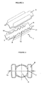
figure 3 représente une vue en perspective des deux demi-coquilles constitutives du dispositif d'atténuation des bruits à l'état non assemblé des deux demi-coquilles ; - la
figure 4 représente une vue en coupe du dispositif d'atténuation des bruits à l'état assemblé des demi-coquilles et - la
figure 5 représente une vue en perspective d'une seule demi-coquille.
- the
figure 1 represents the state of the art; - the
figure 2 represents a schematic view of the portion of the air intake circuit between a turbocharger and a cooler on which is integrated a noise attenuation device according to the invention; - the
figure 3 represents a perspective view of the two half-shells constituting the unassembled noise attenuation device of the two half-shells; - the
figure 4 represents a sectional view of the noise attenuation device in the assembled state of the half-shells and - the
figure 5 represents a perspective view of a single half-shell.
Comme mentionné ci-dessus, le dispositif d'atténuation des bruits, objet de l'invention, est destiné à être installé sur un circuit d'admission d'air pour moteur à combustion interne, de préférence suralimenté, ou sur un circuit d'admission d'air pour un appareil de climatisation. En effet, les bruits à atténuer sont notamment ceux issus du turbocompresseur 2 et/ou du moteur et/ou de l'appareil de climatisation du véhicule. Dans les exemples représentés, le dispositif d'atténuation des bruits est disposé dans la zone du circuit d'admission d'air s'étendant entre le turbocompresseur 2 et un refroidisseur 3 apte à refroidir l'air issu du turbocompresseur 2. Cette disposition privilégiée permet de réunir en un seul et même élément des fonctions d'atténuation des bruits et de conduite rigide de circulation d'air qui, jusqu'à présent, étaient réalisées sous forme de deux éléments différenciés.As mentioned above, the noise attenuation device, object of the invention, is intended to be installed on an air intake circuit for an internal combustion engine, preferably supercharged, or on a circuit of air intake for an air conditioning unit. Indeed, the noises to be attenuated are in particular those from the
Ce dispositif d'atténuation des bruits se présente sous forme d'une section 1 de conduite intégrable par chacune de ses extrémités au circuit d'admission d'air. L'une des extrémités de la section 1 de conduite constitue une entrée 2A d'air tandis que l'autre extrémité constitue une sortie 2B d'air. Dans les exemples représentés, la section 1 de conduite présente à chacune de ses extrémités une section de dimension réduite pour constituer un embout de raccordement solidarisable au reste du circuit d'admission d'air, de préférence par soudure étanche. Ainsi, les embouts de raccordement, formés d'une seule pièce avec la section 1 de conduite, s'étendent à chacune des extrémités de la section 1 de conduite au-delà de l'épaulement formé par le rétrécissement de la section. Cette section 1 de conduite est formée par l'assemblage de deux demi-coquilles représentée en 3 et 4 aux figures. Cette section 1 de conduite est cloisonnée longitudinalement pour délimiter, le long d'un passage d'air axial reliant l'entrée 2A d'air et la sortie 2B de la section 1 de conduite, au moins un volume borgne constitué d'une chambre 6 de résonance. Ce passage d'air axial est appelé section 5 principale de conduit. Ce passage axial peut ainsi communiquer, par l'intermédiaire d'au moins une ouverture 7, avec le volume borgne constitutif de la chambre 6 de résonance pour établir une communication d'air entre la chambre 6 de résonance et la section 5 principale de conduit. De manière caractéristique à l'invention, chaque demi-coquille 3, 4 de la section 1 de conduite est cloisonnée à l'aide d'au moins une cloison 8, 9 longitudinale. Cette cloison, représentée en 8 pour la demi-coquille 3 et en 9 pour la demi-coquille 4, est venue de moulage avec la demi-coquille. Elle prend naissance sur la paroi de fond de la demi-coquille et s'étend avec son bord 12 libre au moins jusque dans le plan de joint 13 des demi-coquilles 3, 4. Les cloisons 8 ou 9 viennent ainsi en contact d'appui ponctuel par leur bord 12 libre à l'état assemblé des demi-coquilles 3, 4. Chaque cloison 8, 9 est munie, sur son bord libre, d'encoches 14 constituant, à l'état assemblé des demi-coquilles 3 et 4, l'ouverture 7 de communication entre chambre 6 de résonance et section 5 principale de conduit. Le fond de la demi-coquille peut affecter un grand nombre de formes. Dans les exemples représentés, le fond de la demi-coquille est constitué, vu en coupe transversale, d'une portion concave correspondant à la zone servant à délimiter la portion de la section 5 principale de conduit jouxtée de chaque côté par deux renflements constituant la partie de fond de la chambre 6 délimitée au moyen de ladite demi-coquille. Bien évidemment, d'autres profils de chambre auraient pu être adoptés notamment un profil festonné plus régulier. La réalisation de la paroi de fond de chaque demi-coquille sous forme d'une paroi polylobée permet d'accroître le volume des chambres de résonance.This noise attenuation device is in the form of a
Pour permettre une atténuation des bruits produits dans une large bande de fréquences, le volume de résonance délimité par les cloisons 8, 9 longitudinales en regard des demi-coquilles 3, 4 est compartimenté par l'intermédiaire de parois 10, 11 transversales venues de moulage avec chaque demi-coquille 3, 4. Ces parois transversales, représentées en 10 pour la demi-coquille 3 et en 11 pour la demi-coquille 4, s'étendent, avec leur bord libre 15, au moins jusque dans le plan de joint des demi-coquilles. Ces parois transversales viennent ainsi par leur bord libre en contact d'appui à l'état assemblé des demi-coquilles 3, 4 de manière à délimiter le long de la section 5 principale de conduite une pluralité de chambres 6 alignées de type résonateur de Helmholtz autorisant une atténuation large bande des bruits.To allow attenuation of the noises produced in a broad band of frequencies, the resonance volume delimited by the
Dans les exemples représentés, chaque demi-coquille 3, ou respectivement 4, comporte deux parois longitudinales 8, ou respectivement 9, parallèles disposées de part et d'autre de la section 5 principale de conduite de manière à présenter deux séries de chambres 6 de résonance aux caractéristiques acoustiques identiques ou différentes. Ces chambres 6 de résonance peuvent ainsi présenter un volume croissant depuis l'entrée 2A d'air en direction de la sortie 2B d'air de ladite section 1 de conduite. L'écartement entre les parois transversales 10 ou respectivement 11, d'une part, la forme et les dimensions des encoches 14 de la paroi longitudinale 8 ou respectivement 9 d'autre part sont choisis en fonction de la plage de fréquence du bruit à atténuer. Dans les exemples représentés, les parois 10 et 11 de cloisonnement transversales des demi-coquilles 3, 4 sont respectivement reliées à la paroi 8, 9 longitudinale, de ladite demi-coquille 3, 4, dans la zone de ladite paroi 8, 9 longitudinale s'étendant entre deux encoches 14, de manière à former autant de chambres 6 que d'encoches 14. Ainsi, dans l'exemple représenté, le dispositif d'atténuation des bruits comporte, de part et d'autre de la section 5 principale de conduite, à chaque fois une série de cinq chambres, soit au total dix chambres de résonance. Chaque chambre d'une série de chambres est dimensionnée de manière différente, les chambres étant identiques d'une série à une autre du fait que les demi-coquilles sont, pour des raisons de simplification de la fabrication, réalisées identiques. Les deux séries de chambres sont réalisées symétriques par rapport au plan longitudinal médian de la section de conduite.In the examples shown, each half-
L'assemblage des demi-coquilles entre elles est obtenu grâce au fait que chaque demi-coquille présente le long de ses bords longitudinaux un rebord dont la face externe est destinée à venir entrer en contact d'appui avec la face externe du rebord de la demi-coquille correspondante pour constituer un plan de joint 13 des demi-coquilles à l'état assemblé. Au cours de cet assemblage des demi-coquilles entre elles, les bords 12, 15 libres en contact d'appui des parois longitudinales 8, 9 et transversales 10, 11 sont assemblés l'un à l'autre de manière étanche, de préférence soudés. Ainsi, les chambres 6 délimitées ne communiquent pas entre elles. Il aurait également pu être prévu de manière analogue de réaliser des encoches dans les parois transversales 10, 11 de manière à assurer une communication entre les chambres 6 de résonance.The assembly of the half-shells between them is obtained thanks to the fact that each half-shell has along its longitudinal edges a flange whose outer face is intended to come into bearing contact with the outer face of the rim of the corresponding half-shell to form a
On note que, dans les exemples représentés, la réduction de section à chacune des extrémités de la section 1 de conduite pour délimiter des embouts de raccordement solidarisables au reste du circuit d'admission d'air permet de délimiter une zone d'épaulement. Les parois longitudinales 8, 9 de cloisonnement s'étendent dans la partie à section élargie de la section 1 de conduite au droit dudit épaulement.It is noted that, in the examples shown, the section reduction at each of the ends of the
Claims (11)
- A device for attenuating noises on an air admission circuit for an internal combustion preferably turbocharged engine, or an air-conditioning apparatus, these noises notably stemming from the turbocompressor (2) and/or from the engine and/or from the air-conditioning apparatus of the vehicle, this device for attenuating noises appearing as a conduit section (1) integrable by each of its ends, respectively forming an inlet (2A) and an outlet (2B) for the air admission circuit, this conduit section(1) stemming from the assembly of two half-shells (3,4), being partitioned longitudinally in order to delimit along an axial air passage connecting the air inlet (2A) and the air outlet (2B) and called a main conduit section (5), at least one blind volume consisting of a resonance chamber (6) communicating via at least one aperture (7) with said main conduit section (5) in order to establish air communication between the resonance chamber (6) and the main conduit section (5),
characterized in that each half-shell (3,4) of the conduit section(1) is partitioned with at least one longitudinal partition (8,9) originating on the bottom wall of the half-shells (3, 4) and extending with its free edge (12) right into the gasket plane (13) of the half-shells (3, 4), said partition (8, 9) coming into point-like supporting contact by their free edge (12) in the assembled condition of the half-shells (3,4), each partition (8,9) being provided on its free end with notches (14) forming, in the assembled condition of the half-shells (3,4), the communication aperture (7) between the resonance chamber (6) and the main conduit section (5). - The device for attenuating noises according to claim 1,
characterized in that the resonance volume delimited by the longitudinal partitions (8, 9) facing the half-shells (3; 4) is divided into compartments via transverse walls (10, 11) made with each half-shell (8, 9) by molding, these transverse rows (10, 11) which extend, with their free edge, at least right into the gasket plane of the half-shells coming into supporting contact with their free edge in the assembled condition of the half-shells (3, 4) so as to delimit along the main conduit section (5) a plurality of aligned chambers (6) of the Helmholtz resonator type allowing wide band attenuation of the noises. - The device for attenuating noises according to claim 2,
characterized in that the transverse partitioning walls (10, 11) of each half-shell (3, 4) are connected to the longitudinal wall (8, 9), of said half-shell (3, 4), in the area of said longitudinal wall (8, 9) extending between two notches (14), so as to form as many chambers (6) as there are notches (14). - The device for attenuating noises according to claim 2,
characterized in that the free edges (12, 15) in contact and bearing upon the longitudinal (8, 9) and transverse (10, 11) walls are sealably assembled with each other, preferably welded during the assembling of the half-shells (3, 4) together. - The device for attenuating noises according to claims 2 to 4,
characterized in that the resonance chambers (6) have a volume which increases from the air inlet (2A) to the air outlet (2B) of said conduit section (1). - The device for attenuating noises according to claims 2 to 5,
characterized in that the gap between the transverse walls (10, 11) on the one hand, the shape and dimensions of the notches (14) of the longitudinal walls (8, 9) on the other hand are selected depending on the frequency range of the noise to be attenuated. - The device for attenuating noises according to claims 1 to 6, characterized in that the half-shells (3, 4) are identical.
- The device for attenuating noises according to claims 1 to 7,
characterized in that each half-shell (3, 4) includes two parallel longitudinal walls (8, 9) positioned on either side of the main conduit section (5) so as to have two resonance chamber (6) series with identical or different acoustic characteristics. - The device for attenuating noises according to claims 1 to 8,
characterized in that the conduit section (1) has at each of its ends a section of reduced size in order to form a connecting endpiece which may be firmly attached to the remainder of the air admission circuit, preferably by leak-proof welding. - An air admission circuit for a preferably overcharged engine or an air-conditioning apparatus, of the type equipped with a device for attenuating noises, these noises notably stemming from the operation of the turbocompressor (2) and/or of the engine and/or air-conditioning apparatus of the vehicle, this device for attenuating noises appearing as a conduit section (1) integrable by each of its ends forming an air inlet (2A) and an air outlet (2B) for the air admission circuit, this conduit section (1) stemming from the assembly of both half-shells (3, 4), being partitioned longitudinally in order to delimit a long and axial air passage connecting the air inlet (2A) and the air outlet (2B) and called the main conduit section (5), at least one blind volume consisting of a resonance chamber (6) communicating via at least one aperture (7) with said main conduit section in order to establish air communication between the resonance chamber (6) and the main conduit section (5), characterized in that the device for attenuating noises of the air admission circuit is in accordance with any of claims 1 to 9.
- The air admission circuit according to claim 10,
characterized in that the device for attenuating the noises is positioned in the area of the air admission circuit between the turbo-compressor (2) and a cooler (3) capable of cooling the air from the turbocompressor (2).
Applications Claiming Priority (2)
| Application Number | Priority Date | Filing Date | Title |
|---|---|---|---|
| FR0314828 | 2003-12-17 | ||
| FR0314828A FR2864168B1 (en) | 2003-12-17 | 2003-12-17 | NOISE MITIGATION DEVICE ON AN AIR INTAKE CIRCUIT FOR INTERNAL COMBUSTION ENGINE AND AIR INTAKE CIRCUIT FOR ENGINE PROVIDED WITH SUCH A NOISE MITIGATION DEVICE |
Publications (3)
| Publication Number | Publication Date |
|---|---|
| EP1553284A1 EP1553284A1 (en) | 2005-07-13 |
| EP1553284B1 true EP1553284B1 (en) | 2011-02-16 |
| EP1553284B8 EP1553284B8 (en) | 2011-03-30 |
Family
ID=34586422
Family Applications (1)
| Application Number | Title | Priority Date | Filing Date |
|---|---|---|---|
| EP04292929A Not-in-force EP1553284B8 (en) | 2003-12-17 | 2004-12-08 | Air intake silencing device especially for turbocharged engines or air conditioner and intake circuit with such a device |
Country Status (4)
| Country | Link |
|---|---|
| EP (1) | EP1553284B8 (en) |
| AT (1) | ATE498771T1 (en) |
| DE (1) | DE602004031404D1 (en) |
| FR (1) | FR2864168B1 (en) |
Families Citing this family (6)
| Publication number | Priority date | Publication date | Assignee | Title |
|---|---|---|---|---|
| FR2894644B1 (en) | 2005-12-12 | 2009-04-03 | Trelleborg Fluid & Acoustic Solutions Tfas | DEVICE FOR ATTENUATING THE NOISE OF AN AIR CIRCUIT CIRCUIT, IN PARTICULAR FOR AN INTERNAL COMBUSTION ENGINE |
| FR2945839B1 (en) * | 2009-05-20 | 2012-10-26 | Mann & Hummel Gmbh | ACOUSTIC DEVICE FOR THE SOUNDPROOFING OF INTERNAL COMBUSTION ENGINES. |
| DE102010022780B4 (en) * | 2010-06-04 | 2014-02-13 | Mann + Hummel Gmbh | Broadband silencer |
| DE102011120148A1 (en) * | 2011-12-03 | 2013-06-06 | GM Global Technology Operations LLC (n. d. Gesetzen des Staates Delaware) | Silencer with a resonator insertable in a circular path insert part |
| DE102013201313A1 (en) | 2012-02-23 | 2013-08-29 | Ford Global Technologies, Llc | Internal heat exchanger for air conditioner of motor vehicle, has high pressure side and low pressure side, where heat exchanger is formed in spatial-bodily manner so that pulsations of passed through refrigerants are predominantly damped |
| DE202019106299U1 (en) * | 2019-11-12 | 2021-02-15 | Woco Industrietechnik Gmbh | Air supply line for coupling to an air consumer in a motor vehicle, arrangement for air supply and use of an air supply line |
Family Cites Families (6)
| Publication number | Priority date | Publication date | Assignee | Title |
|---|---|---|---|---|
| US5302783A (en) * | 1992-12-21 | 1994-04-12 | Abc Group | Resonator |
| JPH10187162A (en) * | 1996-12-26 | 1998-07-14 | Inoac Corp | Resonator |
| DE19855708B4 (en) * | 1998-12-03 | 2009-04-30 | Denker, Dietrich, Prof. Dr.-Ing. | Pipe chamber damper |
| DE10026355B4 (en) * | 2000-05-27 | 2010-06-17 | Mahle Filtersysteme Gmbh | Sound-absorbing air duct |
| JP4453854B2 (en) * | 2000-10-31 | 2010-04-21 | 株式会社イノアックコーポレーション | Intake duct for vehicle |
| JP2004011604A (en) * | 2002-06-11 | 2004-01-15 | Denso Corp | Intake air device for internal combustion engine |
-
2003
- 2003-12-17 FR FR0314828A patent/FR2864168B1/en not_active Expired - Fee Related
-
2004
- 2004-12-08 AT AT04292929T patent/ATE498771T1/en not_active IP Right Cessation
- 2004-12-08 DE DE602004031404T patent/DE602004031404D1/en active Active
- 2004-12-08 EP EP04292929A patent/EP1553284B8/en not_active Not-in-force
Also Published As
| Publication number | Publication date |
|---|---|
| ATE498771T1 (en) | 2011-03-15 |
| FR2864168B1 (en) | 2008-02-15 |
| FR2864168A1 (en) | 2005-06-24 |
| EP1553284B8 (en) | 2011-03-30 |
| DE602004031404D1 (en) | 2011-03-31 |
| EP1553284A1 (en) | 2005-07-13 |
Similar Documents
| Publication | Publication Date | Title |
|---|---|---|
| EP2295782B1 (en) | Silencing device for an intake line of a thermal engine and intake line incorporating a silencing device | |
| EP2506907B1 (en) | Apparatus for the regulated supply of a gas, in particular an assisted breathing apparatus | |
| EP1553284B1 (en) | Air intake silencing device especially for turbocharged engines or air conditioner and intake circuit with such a device | |
| EP3303815B1 (en) | Apparatus for damping diffused and radiated pipe noises | |
| EP1433948B1 (en) | Air intake silencing device | |
| EP1795733B1 (en) | Device for reducing the noise of an air circulation circuit, in particular for an internal combustion engine | |
| EP2101057B1 (en) | Sound attenuation device for the intake line of a heat engine and intake line including same | |
| CA2761601C (en) | Turbine engine comprising an exhaust-gas guide cone with a sound suppressor | |
| FR2929172A1 (en) | NOISE REDUCING DEVICE FOR THE AIR CONDITIONING CIRCUIT OF A MOTOR VEHICLE, DRIVING AND CIRCUIT INCORPORATING IT | |
| FR2840652A1 (en) | Attenuation device for noises coming form i.c. engine operation and vehicle air conditioning system comprises membrane responding to predetermined vibration frequency and is positioned on hole in air inlet pipe | |
| FR2946120A1 (en) | Acoustic attenuation device for intake line of e.g. turbocharged engine, of motor vehicle, has radial partition axially displaced towards extension of inlet end fitting opposed to another extension towards which edge is extended | |
| EP2429843B1 (en) | Vehicle air conditioning loop with a volumic expansion chamber | |
| FR3076318A1 (en) | Sound generation device and vehicle exhaust system | |
| FR2871547A1 (en) | Gas noise attenuation device for internal combustion engine of motor vehicle, has outer tube defining closed chamber with conduit and comprising wall not parallel to wall of conduit on section of length of chamber | |
| FR3002002A1 (en) | Noise attenuation device for compressed gas conveying line of car's turbocharged internal combustion engine, has peripheral chamber whose depth corresponding to partition and wall separation distance varies according to azimuth around axis | |
| EP1712382B1 (en) | Ventilation device for a vehicle including noise reduction means | |
| FR2875560A1 (en) | Centrifugal fan for e.g. ventilating equipment, has diffuser with constant section, and volute tongue inclined with respect to wheel axle at preset inclination angle of low value and situated in plane parallel to axle | |
| FR2913463A1 (en) | Noise reducing device for motor vehicle, has resonator formed of base directly communicating with conduit via small section opening, and cover fixed on base for forming attenuation cavity, where base forms integral part of conduit | |
| FR2892344A1 (en) | DEVICE FOR VENTILATION OF A MOTOR VEHICLE COMPRISING NOISE MITIGATION MEANS | |
| FR2840653A1 (en) | NOISE MITIGATION DEVICE ON AN AIR INTAKE CIRCUIT FOR A SUPERIOR PREFERENCE MOTOR OR AIR CONDITIONING APPARATUS AND ADMISSION CIRCUIT EQUIPPED WITH SUCH A DEVICE | |
| FR2894645A1 (en) | Gas pipe with wide acoustic attenuation, e.g. for air inlets on car engines, has an absorption silencer or multi-orifice broad-band resonator for low frequencies and four quarter-wave resonators for high frequencies | |
| EP2354524B1 (en) | Acoustic attenuation device for an intake line of a thermal engine, flexible tube and intake line comprising such a device | |
| FR2925611A3 (en) | Acoustic resonator for air filter of motor vehicle, has projector with protector connected to main body for forming hollow body, where main body has opening for changing bulb and connected to upstream air inlet pipe by additional pipe | |
| FR2643677A1 (en) | SILENCER FOR AN EXHAUST SYSTEM OF A VEHICLE | |
| FR2848613A1 (en) | Internal combustion engine air supply distributor, has case in inner space that is coupled to outlet ducts, and intermediate shell defining common inner volume space and placed between case and hood |
Legal Events
| Date | Code | Title | Description |
|---|---|---|---|
| PUAI | Public reference made under article 153(3) epc to a published international application that has entered the european phase |
Free format text: ORIGINAL CODE: 0009012 |
|
| AK | Designated contracting states |
Kind code of ref document: A1 Designated state(s): AT BE BG CH CY CZ DE DK EE ES FI FR GB GR HU IE IS IT LI LT LU MC NL PL PT RO SE SI SK TR |
|
| AX | Request for extension of the european patent |
Extension state: AL BA HR LV MK YU |
|
| 17P | Request for examination filed |
Effective date: 20051013 |
|
| AKX | Designation fees paid |
Designated state(s): AT BE BG CH CY CZ DE DK EE ES FI FR GB GR HU IE IS IT LI LT LU MC NL PL PT RO SE SI SK TR |
|
| RAP1 | Party data changed (applicant data changed or rights of an application transferred) |
Owner name: TRELLEBORG FLUID & ACOUSTIC SOLUTIONS (TFAS) |
|
| GRAP | Despatch of communication of intention to grant a patent |
Free format text: ORIGINAL CODE: EPIDOSNIGR1 |
|
| GRAS | Grant fee paid |
Free format text: ORIGINAL CODE: EPIDOSNIGR3 |
|
| GRAA | (expected) grant |
Free format text: ORIGINAL CODE: 0009210 |
|
| AK | Designated contracting states |
Kind code of ref document: B1 Designated state(s): AT BE BG CH CY CZ DE DK EE ES FI FR GB GR HU IE IS IT LI LT LU MC NL PL PT RO SE SI SK TR |
|
| REG | Reference to a national code |
Ref country code: GB Ref legal event code: FG4D Free format text: NOT ENGLISH |
|
| REG | Reference to a national code |
Ref country code: CH Ref legal event code: EP |
|
| RAP2 | Party data changed (patent owner data changed or rights of a patent transferred) |
Owner name: TRISTONE FLOWTECH SOLUTIONS (TFS) |
|
| REG | Reference to a national code |
Ref country code: IE Ref legal event code: FG4D Free format text: LANGUAGE OF EP DOCUMENT: FRENCH |
|
| REF | Corresponds to: |
Ref document number: 602004031404 Country of ref document: DE Date of ref document: 20110331 Kind code of ref document: P |
|
| REG | Reference to a national code |
Ref country code: DE Ref legal event code: R096 Ref document number: 602004031404 Country of ref document: DE Effective date: 20110331 |
|
| REG | Reference to a national code |
Ref country code: DE Ref legal event code: R081 Ref document number: 602004031404 Country of ref document: DE Owner name: TRISTONE FLOWTECH SOLUTIONS (TFS), FR Free format text: FORMER OWNER: TRELLEBORG FLUID & ACOUSTIC SOLUTIONS (TFAS), CARQUEFOU, FR Effective date: 20110215 |
|
| REG | Reference to a national code |
Ref country code: NL Ref legal event code: VDEP Effective date: 20110216 |
|
| LTIE | Lt: invalidation of european patent or patent extension |
Effective date: 20110216 |
|
| PG25 | Lapsed in a contracting state [announced via postgrant information from national office to epo] |
Ref country code: GR Free format text: LAPSE BECAUSE OF FAILURE TO SUBMIT A TRANSLATION OF THE DESCRIPTION OR TO PAY THE FEE WITHIN THE PRESCRIBED TIME-LIMIT Effective date: 20110517 Ref country code: ES Free format text: LAPSE BECAUSE OF FAILURE TO SUBMIT A TRANSLATION OF THE DESCRIPTION OR TO PAY THE FEE WITHIN THE PRESCRIBED TIME-LIMIT Effective date: 20110527 Ref country code: LT Free format text: LAPSE BECAUSE OF FAILURE TO SUBMIT A TRANSLATION OF THE DESCRIPTION OR TO PAY THE FEE WITHIN THE PRESCRIBED TIME-LIMIT Effective date: 20110216 Ref country code: PT Free format text: LAPSE BECAUSE OF FAILURE TO SUBMIT A TRANSLATION OF THE DESCRIPTION OR TO PAY THE FEE WITHIN THE PRESCRIBED TIME-LIMIT Effective date: 20110616 Ref country code: SE Free format text: LAPSE BECAUSE OF FAILURE TO SUBMIT A TRANSLATION OF THE DESCRIPTION OR TO PAY THE FEE WITHIN THE PRESCRIBED TIME-LIMIT Effective date: 20110216 |
|
| PG25 | Lapsed in a contracting state [announced via postgrant information from national office to epo] |
Ref country code: BG Free format text: LAPSE BECAUSE OF FAILURE TO SUBMIT A TRANSLATION OF THE DESCRIPTION OR TO PAY THE FEE WITHIN THE PRESCRIBED TIME-LIMIT Effective date: 20110516 Ref country code: NL Free format text: LAPSE BECAUSE OF FAILURE TO SUBMIT A TRANSLATION OF THE DESCRIPTION OR TO PAY THE FEE WITHIN THE PRESCRIBED TIME-LIMIT Effective date: 20110216 Ref country code: CY Free format text: LAPSE BECAUSE OF FAILURE TO SUBMIT A TRANSLATION OF THE DESCRIPTION OR TO PAY THE FEE WITHIN THE PRESCRIBED TIME-LIMIT Effective date: 20110216 Ref country code: FI Free format text: LAPSE BECAUSE OF FAILURE TO SUBMIT A TRANSLATION OF THE DESCRIPTION OR TO PAY THE FEE WITHIN THE PRESCRIBED TIME-LIMIT Effective date: 20110216 Ref country code: SI Free format text: LAPSE BECAUSE OF FAILURE TO SUBMIT A TRANSLATION OF THE DESCRIPTION OR TO PAY THE FEE WITHIN THE PRESCRIBED TIME-LIMIT Effective date: 20110216 Ref country code: PL Free format text: LAPSE BECAUSE OF FAILURE TO SUBMIT A TRANSLATION OF THE DESCRIPTION OR TO PAY THE FEE WITHIN THE PRESCRIBED TIME-LIMIT Effective date: 20110216 Ref country code: AT Free format text: LAPSE BECAUSE OF FAILURE TO SUBMIT A TRANSLATION OF THE DESCRIPTION OR TO PAY THE FEE WITHIN THE PRESCRIBED TIME-LIMIT Effective date: 20110216 |
|
| REG | Reference to a national code |
Ref country code: IE Ref legal event code: FD4D |
|
| PG25 | Lapsed in a contracting state [announced via postgrant information from national office to epo] |
Ref country code: DK Free format text: LAPSE BECAUSE OF FAILURE TO SUBMIT A TRANSLATION OF THE DESCRIPTION OR TO PAY THE FEE WITHIN THE PRESCRIBED TIME-LIMIT Effective date: 20110216 Ref country code: IE Free format text: LAPSE BECAUSE OF FAILURE TO SUBMIT A TRANSLATION OF THE DESCRIPTION OR TO PAY THE FEE WITHIN THE PRESCRIBED TIME-LIMIT Effective date: 20110216 Ref country code: EE Free format text: LAPSE BECAUSE OF FAILURE TO SUBMIT A TRANSLATION OF THE DESCRIPTION OR TO PAY THE FEE WITHIN THE PRESCRIBED TIME-LIMIT Effective date: 20110216 |
|
| PG25 | Lapsed in a contracting state [announced via postgrant information from national office to epo] |
Ref country code: RO Free format text: LAPSE BECAUSE OF FAILURE TO SUBMIT A TRANSLATION OF THE DESCRIPTION OR TO PAY THE FEE WITHIN THE PRESCRIBED TIME-LIMIT Effective date: 20110216 Ref country code: SK Free format text: LAPSE BECAUSE OF FAILURE TO SUBMIT A TRANSLATION OF THE DESCRIPTION OR TO PAY THE FEE WITHIN THE PRESCRIBED TIME-LIMIT Effective date: 20110216 Ref country code: CZ Free format text: LAPSE BECAUSE OF FAILURE TO SUBMIT A TRANSLATION OF THE DESCRIPTION OR TO PAY THE FEE WITHIN THE PRESCRIBED TIME-LIMIT Effective date: 20110216 |
|
| PLBE | No opposition filed within time limit |
Free format text: ORIGINAL CODE: 0009261 |
|
| STAA | Information on the status of an ep patent application or granted ep patent |
Free format text: STATUS: NO OPPOSITION FILED WITHIN TIME LIMIT |
|
| 26N | No opposition filed |
Effective date: 20111117 |
|
| REG | Reference to a national code |
Ref country code: DE Ref legal event code: R097 Ref document number: 602004031404 Country of ref document: DE Effective date: 20111117 |
|
| PG25 | Lapsed in a contracting state [announced via postgrant information from national office to epo] |
Ref country code: IT Free format text: LAPSE BECAUSE OF FAILURE TO SUBMIT A TRANSLATION OF THE DESCRIPTION OR TO PAY THE FEE WITHIN THE PRESCRIBED TIME-LIMIT Effective date: 20110216 |
|
| PGFP | Annual fee paid to national office [announced via postgrant information from national office to epo] |
Ref country code: DE Payment date: 20111222 Year of fee payment: 8 |
|
| BERE | Be: lapsed |
Owner name: TRELLEBORG FLUID & ACOUSTIC SOLUTIONS (TFAS) Effective date: 20111231 |
|
| PG25 | Lapsed in a contracting state [announced via postgrant information from national office to epo] |
Ref country code: MC Free format text: LAPSE BECAUSE OF NON-PAYMENT OF DUE FEES Effective date: 20111231 |
|
| REG | Reference to a national code |
Ref country code: CH Ref legal event code: PL |
|
| PG25 | Lapsed in a contracting state [announced via postgrant information from national office to epo] |
Ref country code: LI Free format text: LAPSE BECAUSE OF NON-PAYMENT OF DUE FEES Effective date: 20111231 Ref country code: BE Free format text: LAPSE BECAUSE OF NON-PAYMENT OF DUE FEES Effective date: 20111231 Ref country code: CH Free format text: LAPSE BECAUSE OF NON-PAYMENT OF DUE FEES Effective date: 20111231 |
|
| PG25 | Lapsed in a contracting state [announced via postgrant information from national office to epo] |
Ref country code: LU Free format text: LAPSE BECAUSE OF NON-PAYMENT OF DUE FEES Effective date: 20111208 |
|
| PG25 | Lapsed in a contracting state [announced via postgrant information from national office to epo] |
Ref country code: IS Free format text: LAPSE BECAUSE OF FAILURE TO SUBMIT A TRANSLATION OF THE DESCRIPTION OR TO PAY THE FEE WITHIN THE PRESCRIBED TIME-LIMIT Effective date: 20110216 |
|
| GBPC | Gb: european patent ceased through non-payment of renewal fee |
Effective date: 20121208 |
|
| PG25 | Lapsed in a contracting state [announced via postgrant information from national office to epo] |
Ref country code: TR Free format text: LAPSE BECAUSE OF FAILURE TO SUBMIT A TRANSLATION OF THE DESCRIPTION OR TO PAY THE FEE WITHIN THE PRESCRIBED TIME-LIMIT Effective date: 20110216 |
|
| REG | Reference to a national code |
Ref country code: DE Ref legal event code: R119 Ref document number: 602004031404 Country of ref document: DE Effective date: 20130702 |
|
| PG25 | Lapsed in a contracting state [announced via postgrant information from national office to epo] |
Ref country code: DE Free format text: LAPSE BECAUSE OF NON-PAYMENT OF DUE FEES Effective date: 20130702 Ref country code: HU Free format text: LAPSE BECAUSE OF FAILURE TO SUBMIT A TRANSLATION OF THE DESCRIPTION OR TO PAY THE FEE WITHIN THE PRESCRIBED TIME-LIMIT Effective date: 20110216 |
|
| PG25 | Lapsed in a contracting state [announced via postgrant information from national office to epo] |
Ref country code: GB Free format text: LAPSE BECAUSE OF NON-PAYMENT OF DUE FEES Effective date: 20121208 |
|
| REG | Reference to a national code |
Ref country code: FR Ref legal event code: PLFP Year of fee payment: 12 |
|
| REG | Reference to a national code |
Ref country code: FR Ref legal event code: PLFP Year of fee payment: 13 |
|
| REG | Reference to a national code |
Ref country code: FR Ref legal event code: PLFP Year of fee payment: 14 |
|
| PGFP | Annual fee paid to national office [announced via postgrant information from national office to epo] |
Ref country code: FR Payment date: 20191219 Year of fee payment: 16 |
|
| PG25 | Lapsed in a contracting state [announced via postgrant information from national office to epo] |
Ref country code: FR Free format text: LAPSE BECAUSE OF NON-PAYMENT OF DUE FEES Effective date: 20201231 |