EP3636909A1 - Vorrichtung zur lärmreduzierung für einspeiseleitung eines wärmeverbrennungsmotors, der mit einem turbokompressor ausgestattet ist - Google Patents
Vorrichtung zur lärmreduzierung für einspeiseleitung eines wärmeverbrennungsmotors, der mit einem turbokompressor ausgestattet ist Download PDFInfo
- Publication number
- EP3636909A1 EP3636909A1 EP19197918.6A EP19197918A EP3636909A1 EP 3636909 A1 EP3636909 A1 EP 3636909A1 EP 19197918 A EP19197918 A EP 19197918A EP 3636909 A1 EP3636909 A1 EP 3636909A1
- Authority
- EP
- European Patent Office
- Prior art keywords
- attenuation device
- acoustic
- acoustic attenuation
- absorption element
- fibers
- Prior art date
- Legal status (The legal status is an assumption and is not a legal conclusion. Google has not performed a legal analysis and makes no representation as to the accuracy of the status listed.)
- Pending
Links
- 238000002485 combustion reaction Methods 0.000 title claims abstract description 9
- 238000010521 absorption reaction Methods 0.000 claims abstract description 46
- 230000002093 peripheral effect Effects 0.000 claims abstract description 27
- 239000011148 porous material Substances 0.000 claims abstract description 13
- 238000000926 separation method Methods 0.000 claims abstract description 4
- -1 polypropylene Polymers 0.000 claims description 34
- 239000000835 fiber Substances 0.000 claims description 21
- 239000000463 material Substances 0.000 claims description 17
- 239000004698 Polyethylene Substances 0.000 claims description 14
- 239000004743 Polypropylene Substances 0.000 claims description 14
- 229920000573 polyethylene Polymers 0.000 claims description 14
- 229920001155 polypropylene Polymers 0.000 claims description 14
- 229920005830 Polyurethane Foam Polymers 0.000 claims description 8
- 229920005594 polymer fiber Polymers 0.000 claims description 8
- 239000011496 polyurethane foam Substances 0.000 claims description 8
- 230000035699 permeability Effects 0.000 claims description 6
- 239000006260 foam Substances 0.000 claims description 4
- 229920000914 Metallic fiber Polymers 0.000 claims description 3
- 230000003247 decreasing effect Effects 0.000 claims description 3
- 238000011144 upstream manufacturing Methods 0.000 claims description 2
- 238000005192 partition Methods 0.000 description 11
- 239000012530 fluid Substances 0.000 description 5
- 239000004753 textile Substances 0.000 description 4
- 241000195940 Bryophyta Species 0.000 description 3
- 230000003628 erosive effect Effects 0.000 description 3
- 239000002657 fibrous material Substances 0.000 description 3
- 235000011929 mousse Nutrition 0.000 description 3
- 239000006262 metallic foam Substances 0.000 description 2
- 230000000644 propagated effect Effects 0.000 description 2
- 239000000470 constituent Substances 0.000 description 1
- 230000006866 deterioration Effects 0.000 description 1
- 238000002955 isolation Methods 0.000 description 1
- 238000004519 manufacturing process Methods 0.000 description 1
- 238000005259 measurement Methods 0.000 description 1
- 239000000203 mixture Substances 0.000 description 1
- 238000012986 modification Methods 0.000 description 1
- 230000004048 modification Effects 0.000 description 1
- 229920000642 polymer Polymers 0.000 description 1
- 238000006467 substitution reaction Methods 0.000 description 1
- 238000003466 welding Methods 0.000 description 1
Images


Classifications
-
- F—MECHANICAL ENGINEERING; LIGHTING; HEATING; WEAPONS; BLASTING
- F02—COMBUSTION ENGINES; HOT-GAS OR COMBUSTION-PRODUCT ENGINE PLANTS
- F02M—SUPPLYING COMBUSTION ENGINES IN GENERAL WITH COMBUSTIBLE MIXTURES OR CONSTITUENTS THEREOF
- F02M35/00—Combustion-air cleaners, air intakes, intake silencers, or induction systems specially adapted for, or arranged on, internal-combustion engines
- F02M35/12—Intake silencers ; Sound modulation, transmission or amplification
- F02M35/1272—Intake silencers ; Sound modulation, transmission or amplification using absorbing, damping, insulating or reflecting materials, e.g. porous foams, fibres, rubbers, fabrics, coatings or membranes
-
- F—MECHANICAL ENGINEERING; LIGHTING; HEATING; WEAPONS; BLASTING
- F02—COMBUSTION ENGINES; HOT-GAS OR COMBUSTION-PRODUCT ENGINE PLANTS
- F02M—SUPPLYING COMBUSTION ENGINES IN GENERAL WITH COMBUSTIBLE MIXTURES OR CONSTITUENTS THEREOF
- F02M35/00—Combustion-air cleaners, air intakes, intake silencers, or induction systems specially adapted for, or arranged on, internal-combustion engines
- F02M35/12—Intake silencers ; Sound modulation, transmission or amplification
- F02M35/1255—Intake silencers ; Sound modulation, transmission or amplification using resonance
- F02M35/1266—Intake silencers ; Sound modulation, transmission or amplification using resonance comprising multiple chambers or compartments
-
- F—MECHANICAL ENGINEERING; LIGHTING; HEATING; WEAPONS; BLASTING
- F02—COMBUSTION ENGINES; HOT-GAS OR COMBUSTION-PRODUCT ENGINE PLANTS
- F02B—INTERNAL-COMBUSTION PISTON ENGINES; COMBUSTION ENGINES IN GENERAL
- F02B37/00—Engines characterised by provision of pumps driven at least for part of the time by exhaust
-
- F—MECHANICAL ENGINEERING; LIGHTING; HEATING; WEAPONS; BLASTING
- F02—COMBUSTION ENGINES; HOT-GAS OR COMBUSTION-PRODUCT ENGINE PLANTS
- F02B—INTERNAL-COMBUSTION PISTON ENGINES; COMBUSTION ENGINES IN GENERAL
- F02B77/00—Component parts, details or accessories, not otherwise provided for
- F02B77/11—Thermal or acoustic insulation
- F02B77/13—Acoustic insulation
-
- F—MECHANICAL ENGINEERING; LIGHTING; HEATING; WEAPONS; BLASTING
- F02—COMBUSTION ENGINES; HOT-GAS OR COMBUSTION-PRODUCT ENGINE PLANTS
- F02M—SUPPLYING COMBUSTION ENGINES IN GENERAL WITH COMBUSTIBLE MIXTURES OR CONSTITUENTS THEREOF
- F02M2200/00—Details of fuel-injection apparatus, not otherwise provided for
- F02M2200/90—Selection of particular materials
- F02M2200/9023—Fibrous materials
Definitions
- the present invention relates to an acoustic attenuation device for an intake line of a thermal combustion engine equipped with one or more turbochargers.
- Internal combustion engines have a low frequency acoustic component ranging from 30Hz to 1kHz. This component is generated by the opening and closing of the valves, as well as by the resonance of the different engine cavities (combustion chambers, ducts, ).
- turbocharged engines there is a high frequency acoustic component ranging from 800 Hz to 15 kHz. This acoustic component is generated by the turbocharger and can propagate and radiate through the air intake ducts.
- an acoustic attenuation device using open cavities on a main duct in which the gaseous fluid circulates.
- These open cavities can be completely or partially filled with a porous or fibrous material so as to modify the noise attenuation characteristics of the cavities. Since these cavities are open, the porous or fibrous material which it contains is subjected to the flow of gaseous fluid circulating in the main conduit. It can therefore deteriorate over time due to the eroding effect of the gaseous fluid.
- the solution envisaged so far to avoid this deterioration consists in using materials which are more resistant to erosion. In particular, materials of the metallic foam type prove to be particularly effective at this level. However, these materials have the disadvantage of being expensive and of having a relatively low sound absorption power.
- the object of the invention is to propose a device for attenuating noise, which makes it possible to effectively attenuate the noise propagated in the air intake ducts while limiting the cost of manufacturing said ducts.
- the acoustic attenuation device of the invention makes it possible to separate the interior space of the peripheral chamber, in which the sound absorption element is housed, from the interior space of the duct, in which the fluid circulates. gaseous.
- the sound absorption element is therefore no longer in contact with the gaseous fluid. This results in less erosion, which allows the use of fibrous or porous material which is less expensive and which has a sound absorption capacity greater than that of materials of the metallic foam type.
- the invention relates to an air intake assembly for a vehicle, comprising a turbocharger having an air inlet and an air outlet and an acoustic attenuation device as described above.
- the acoustic attenuation device is positioned upstream of the turbocharger.
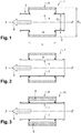
- FIG. 1 With reference to the figure 1 there is shown a known configuration of an acoustic attenuation device for an intake line of a thermal combustion engine equipped with a turbocharger.
- This device 1 comprises in particular a main conduit 2 through which the air or the gas mixture circulates in the direction of circulation S, said conduit 2 extending along a direction axis ZZ '.
- the duct 2 has a substantially cylindrical geometry. It is defined by a peripheral wall 3 having an internal diameter D1.
- the peripheral wall 3 is provided with a through opening 4, said through opening 4 opening into a peripheral chamber 5 of annular shape.
- the peripheral chamber 5 is delimited by the internal walls of a bell 6 of cylindrical shape which is arranged coaxially around the duct 2 so as to completely cover the through opening 4.
- the bell 6 is notably defined by an external diameter D2 and a length L.
- FIG 2 With reference to the figure 2 there is shown another known configuration of an acoustic attenuation device for an intake line of a thermal combustion engine equipped with a turbocharger.
- This device 1 'differs from the device 1 shown in the figure 1 by the presence of a partition wall 7 at the level of the through opening 4.
- This partition wall 7 is formed by a strip of porous materials arranged in the extension of the peripheral wall 3 so as to close the peripheral chamber 5.
- the constituent strip of the wall 7 has a certain permeability, in particular between 650 l / m 2 / s and 1200 l / m 2 / s, and is generally made up of a textile made of polymer fibers or metallic fibers. The wall 7 thus ensures a flow that is substantially free of pressure drop while allowing acoustic attenuation.
- an acoustic attenuation device 10 differs from the device 1 'shown in the figure 2 by the presence of an element of sound absorption 8 inside the peripheral chamber 5.
- the sound absorption element 8 has an annular profile and partially fills, in particular half, the peripheral chamber 5. It can advantageously be fixed on the bell 6 , for example by welding or by clipping, so as to leave a free space between the partition wall 7 and the sound absorption element 8.
- the sound absorption element 8 could advantageously be formed from a material chosen from among polymer foams, in particular polyurethane foams or polyurethane foams covered with a laminated film of polypropylene or polyethylene, the foams preferably having a density of between 8 and 55 kg / m 3 , or among the materials comprising polymer fibers, in particular comprising 30% polypropylene fibers and 70% polyethylene fibers.
- Example 1 corresponds to the configuration shown on the figure 1 , in which the diameter D1 is 56 mm, the diameter D2 is 90 mm and the length L is 90 mm.
- Example 2 corresponds to the configuration shown on the figure 2 , in which the diameter D1 is 56 mm, the diameter D2 is 90 mm and the length L is 90 mm, and in which the partition wall 7 is formed in a textile material made of polymer fibers comprising 30% of polypropylene fibers and 70% polyethylene fibers and has a permeability of 850 l / m 2 / s.
- Example 3 corresponds to the configuration shown on the figure 3 , in which the diameter D1 is 56 mm, the diameter D2 is 90 mm and the length L is 90 mm, in which the partition wall 7 is formed in a textile material made of polymer fibers comprising 30% of polypropylene fibers and 70% polyethylene fiber and has a permeability of 850 l / m 2 / s and in which the sound absorption element 8 is formed from a material of open-cell trenched polyurethane foam covered with a laminated film of polypropylene or polyethylene and having a density of 25 kg / m 3 .
- the sound absorption element 8 is arranged in such a way that the laminated film is directed towards the main duct 2. It can therefore be seen that the sound attenuation of the device of example 3 is at least 5 dB higher than that devices of examples 1 and 2, in particular in the frequency range between 1500 and 2500 Hz, which corresponds to the frequencies generally associated with turbocharged engines.
- an acoustic attenuation device 11 according to a second embodiment of the invention.
- This device 11 differs from the device 10 shown in the figure 3 in that the sound absorption element 8 completely fills the peripheral chamber 5, so that the sound absorption element 8 and the partition wall 7 are in contact.
- FIG 9 With reference to the figure 9 there is shown a graph making it possible to compare the acoustic performances of the device 11 according to the invention with those of the device 1 of the prior art and of the device 10 according to the invention.
- Examples 1 and 3 correspond to those defined above for the figure 8 and example 4 corresponds to the configuration shown on the figure 4 , in which the diameter D1 is 56 mm, the diameter D2 is 90 mm and the length L is 90 mm, in which the partition wall 7 is formed in a textile material made of polymer fibers comprising 30% of polypropylene fibers and 70% polyethylene fiber and has a permeability of 850 l / m 2 / s and in which the sound absorption element 8 is formed from a polyurethane foam material.
- the acoustic attenuation of the device of Example 4 is greater than that of the devices of Examples 1 and 3 in the frequency range between 2000 and 2500 Hz.
- the device of Example 4 can therefore be used preferentially in the event that the frequencies emitted by the turbocharged engine fall within this specific range.
- the sound absorption element 8 is formed from a material comprising polypropylene fibers and polyethylene fibers, preferably in the proportion of 30% of polypropylene fibers and 70% of polyethylene fibers. This type of material has the advantage of being easily compressible, as illustrated on the figure 7 .
- the device 12 shown in the figure 5 differs from the device 10 shown in the figure 3 by the fact that the sound absorption element 8 comprises a first part 81 and a second part 82 contiguous to the first part 81.
- the first and second parts 81, 82 both have an annular shape defined by an external diameter d1, respectively d2, and an internal diameter d1 ', respectively d2'.
- the external diameters d1 and d2 are equal, while the internal diameter d1 'of the first part 81 is greater than the internal diameter d2' of the second part 82, so that, in the first part 81, a space free is present between the partition wall 7 and the sound absorption element 8 and, in the second part 82, the sound absorption element 8 and the partition wall 7 are in contact.
- This device 12 will therefore have different acoustic attenuation characteristics from those of the device 10.
- the device 13 shown in the figure 6 differs from the device 10 shown in the figure 3 by the fact that the sound absorption element 8 has an annular shape defined by a constant external diameter d and an internal diameter continuously decreasing along its length, according to the direction of circulation S, so that, at at least a first end, the sound absorption element 8 and the partition wall 7 are in contact, and, at at least one second end, a free space is present between the partition wall 7 and the element acoustic absorption 8.
- This device 13 will therefore have different acoustic attenuation characteristics from those of device 10.
- the device 14 shown in the figure 7 differs from the device 10 shown in the figure 3 by the fact that the bell 6 has an increasing section in the direction of circulation S, the external diameter D2 increasing in stages.
- the sound absorption element 8 also has an increasing section in the direction of circulation S so as to completely fill the peripheral chamber 5. It has in particular three contiguous parts 83, 84 and 85, whose internal diameters d3 ′, d4 'and d5' are equal and whose external diameters d3, d4 and d5 are defined by the relation d3 ⁇ d4 ⁇ d5.
- This device 14 will therefore have different acoustic attenuation characteristics from those of the device 10.
Landscapes
- Engineering & Computer Science (AREA)
- Chemical & Material Sciences (AREA)
- Combustion & Propulsion (AREA)
- Mechanical Engineering (AREA)
- General Engineering & Computer Science (AREA)
- Supercharger (AREA)
- Soundproofing, Sound Blocking, And Sound Damping (AREA)
Applications Claiming Priority (1)
| Application Number | Priority Date | Filing Date | Title |
|---|---|---|---|
| FR1859280A FR3086978B1 (fr) | 2018-10-08 | 2018-10-08 | Dispositif d'attenuation acoustique pour une ligne d'admission d'un moteur a combustion thermique equipee d'un turbocompresseur |
Publications (1)
| Publication Number | Publication Date |
|---|---|
| EP3636909A1 true EP3636909A1 (de) | 2020-04-15 |
Family
ID=65244165
Family Applications (1)
| Application Number | Title | Priority Date | Filing Date |
|---|---|---|---|
| EP19197918.6A Pending EP3636909A1 (de) | 2018-10-08 | 2019-09-18 | Vorrichtung zur lärmreduzierung für einspeiseleitung eines wärmeverbrennungsmotors, der mit einem turbokompressor ausgestattet ist |
Country Status (2)
| Country | Link |
|---|---|
| EP (1) | EP3636909A1 (de) |
| FR (1) | FR3086978B1 (de) |
Citations (6)
| Publication number | Priority date | Publication date | Assignee | Title |
|---|---|---|---|---|
| US4350223A (en) * | 1980-01-16 | 1982-09-21 | Nissan Motor Co., Ltd. | Silencer |
| FR2551501A1 (fr) * | 1983-08-31 | 1985-03-08 | Nissan Motor | Dispositif d'admission pour un moteur automobile a combustion interne |
| WO1997009527A1 (de) * | 1995-09-05 | 1997-03-13 | Woco Franz-Josef Wolf & Co. | Schalldämpfer |
| EP1255071A1 (de) * | 2001-05-04 | 2002-11-06 | Mecaplast Sam | Schalldämmungsanordnung in einem Kreislauf eines Gasfluidums |
| EP1780398A1 (de) * | 2005-10-25 | 2007-05-02 | Hutchinson | Ansaugschalldämpfer für einer Brennkraftmaschine mit Turbolader |
| WO2017068264A1 (fr) * | 2015-10-19 | 2017-04-27 | Mecaplast France | Dispositif d'atténuation acoustique pour une ligne d'admission |
-
2018
- 2018-10-08 FR FR1859280A patent/FR3086978B1/fr active Active
-
2019
- 2019-09-18 EP EP19197918.6A patent/EP3636909A1/de active Pending
Patent Citations (7)
| Publication number | Priority date | Publication date | Assignee | Title |
|---|---|---|---|---|
| US4350223A (en) * | 1980-01-16 | 1982-09-21 | Nissan Motor Co., Ltd. | Silencer |
| FR2551501A1 (fr) * | 1983-08-31 | 1985-03-08 | Nissan Motor | Dispositif d'admission pour un moteur automobile a combustion interne |
| WO1997009527A1 (de) * | 1995-09-05 | 1997-03-13 | Woco Franz-Josef Wolf & Co. | Schalldämpfer |
| EP1255071A1 (de) * | 2001-05-04 | 2002-11-06 | Mecaplast Sam | Schalldämmungsanordnung in einem Kreislauf eines Gasfluidums |
| FR2824383A1 (fr) | 2001-05-04 | 2002-11-08 | Mecaplast Sa | Dispositif d'attenuation du niveau sonore d'un circuit de fluide gazeux |
| EP1780398A1 (de) * | 2005-10-25 | 2007-05-02 | Hutchinson | Ansaugschalldämpfer für einer Brennkraftmaschine mit Turbolader |
| WO2017068264A1 (fr) * | 2015-10-19 | 2017-04-27 | Mecaplast France | Dispositif d'atténuation acoustique pour une ligne d'admission |
Also Published As
| Publication number | Publication date |
|---|---|
| FR3086978A1 (fr) | 2020-04-10 |
| FR3086978B1 (fr) | 2020-10-23 |
Similar Documents
| Publication | Publication Date | Title |
|---|---|---|
| EP0434578A1 (de) | Auspuffanlage mit Venturi | |
| EP3365547B1 (de) | Schalldämpfende vorrichtung für eine ansaugleitung | |
| FR2746861A1 (fr) | Systeme de silencieux d'aspiration pour motocompresseur de refrigeration | |
| FR2551501A1 (fr) | Dispositif d'admission pour un moteur automobile a combustion interne | |
| WO2016071623A1 (fr) | Conduit intégrant un dispositif d'atténuation acoustique | |
| EP3303815B1 (de) | Vorrichtung zur dämpfung von verbreiteten und abgestrahlten leitungsgeräuschen | |
| EP3636909A1 (de) | Vorrichtung zur lärmreduzierung für einspeiseleitung eines wärmeverbrennungsmotors, der mit einem turbokompressor ausgestattet ist | |
| FR2824383A1 (fr) | Dispositif d'attenuation du niveau sonore d'un circuit de fluide gazeux | |
| EP1433948B1 (de) | Luftansaugdämpfungsanlage | |
| EP1795733B1 (de) | Schalldämpfer zur Verringerung von Luftgeräuschen, insbesondre für interne Brennkraftmaschinen | |
| EP3634712B1 (de) | Verfahren zur herstellung eines lufteinlasskanals | |
| EP1553284B1 (de) | Luftansaugdämpfungsanlage, insbesondere für aufgeladene Brennkraftmaschinen oder Klimaanlage, und Ansaugkanal mit solch einer Anlage | |
| FR2871547A1 (fr) | Dispositif d'attenuation du bruit de gaz dans un conduit, notamment pour vehicule automobile | |
| EP0332481B1 (de) | Rohrförmige Kupplungsleitung mit Schalldämpfungsmitteln | |
| EP1369577B1 (de) | Luftansaugdämpfungsanlage, insbesondere für aufgeladene Brennkraftmaschinen oder Klimaanlage, und Ansaugkanal mit solch einer Anlage | |
| FR2890417A1 (fr) | Silencieux ameliore pour compresseur de fluides, notamment pour compresseur a air pour suspensions de vehicules automobiles | |
| WO2023007077A1 (fr) | Élement d'obturation acoustique | |
| FR2604747A1 (fr) | Silencieux pour flux gazeux | |
| EP3409937A1 (de) | Leitung zum lufteinlass und zur schalldämpfung | |
| FR2854427A1 (fr) | Silencieux pour gaz d'echappement de moteurs a combustion interne. | |
| EP1460243B1 (de) | Schalldämpfungsanlage | |
| FR3123944A1 (fr) | Silencieux d'échappement pour une pile à combustible | |
| FR2707341A1 (fr) | Silencieux pour gaz d'échappement. | |
| FR2766234A1 (fr) | Silencieux pour pot d'echappement | |
| FR2528111A1 (fr) | Silencieux pour vibrateur pneumatique |
Legal Events
| Date | Code | Title | Description |
|---|---|---|---|
| PUAI | Public reference made under article 153(3) epc to a published international application that has entered the european phase |
Free format text: ORIGINAL CODE: 0009012 |
|
| STAA | Information on the status of an ep patent application or granted ep patent |
Free format text: STATUS: THE APPLICATION HAS BEEN PUBLISHED |
|
| AK | Designated contracting states |
Kind code of ref document: A1 Designated state(s): AL AT BE BG CH CY CZ DE DK EE ES FI FR GB GR HR HU IE IS IT LI LT LU LV MC MK MT NL NO PL PT RO RS SE SI SK SM TR |
|
| AX | Request for extension of the european patent |
Extension state: BA ME |
|
| STAA | Information on the status of an ep patent application or granted ep patent |
Free format text: STATUS: REQUEST FOR EXAMINATION WAS MADE |
|
| 17P | Request for examination filed |
Effective date: 20200908 |
|
| RBV | Designated contracting states (corrected) |
Designated state(s): AL AT BE BG CH CY CZ DE DK EE ES FI FR GB GR HR HU IE IS IT LI LT LU LV MC MK MT NL NO PL PT RO RS SE SI SK SM TR |
|
| STAA | Information on the status of an ep patent application or granted ep patent |
Free format text: STATUS: EXAMINATION IS IN PROGRESS |
|
| 17Q | First examination report despatched |
Effective date: 20201016 |
|
| STAA | Information on the status of an ep patent application or granted ep patent |
Free format text: STATUS: EXAMINATION IS IN PROGRESS |
|
| P01 | Opt-out of the competence of the unified patent court (upc) registered |
Effective date: 20230526 |
|
| RAP3 | Party data changed (applicant data changed or rights of an application transferred) |
Owner name: NOVARES FRANCE |
|
| RIC1 | Information provided on ipc code assigned before grant |
Ipc: F02B 37/00 20060101ALN20240702BHEP Ipc: F02M 35/12 20060101AFI20240702BHEP |
|
| RIC1 | Information provided on ipc code assigned before grant |
Ipc: F02B 37/00 20060101ALN20240717BHEP Ipc: F02M 35/12 20060101AFI20240717BHEP |
|
| RIC1 | Information provided on ipc code assigned before grant |
Ipc: F02B 37/00 20060101ALN20240724BHEP Ipc: F02M 35/12 20060101AFI20240724BHEP |
|
| GRAP | Despatch of communication of intention to grant a patent |
Free format text: ORIGINAL CODE: EPIDOSNIGR1 |
|
| STAA | Information on the status of an ep patent application or granted ep patent |
Free format text: STATUS: GRANT OF PATENT IS INTENDED |