EP1553232A1 - Ablaufsiphon für eine Sanitäreinrichtung - Google Patents
Ablaufsiphon für eine Sanitäreinrichtung Download PDFInfo
- Publication number
- EP1553232A1 EP1553232A1 EP04405015A EP04405015A EP1553232A1 EP 1553232 A1 EP1553232 A1 EP 1553232A1 EP 04405015 A EP04405015 A EP 04405015A EP 04405015 A EP04405015 A EP 04405015A EP 1553232 A1 EP1553232 A1 EP 1553232A1
- Authority
- EP
- European Patent Office
- Prior art keywords
- insert
- housing
- siphon according
- siphon
- dip tube
- Prior art date
- Legal status (The legal status is an assumption and is not a legal conclusion. Google has not performed a legal analysis and makes no representation as to the accuracy of the status listed.)
- Granted
Links
Images

Classifications
-
- E—FIXED CONSTRUCTIONS
- E03—WATER SUPPLY; SEWERAGE
- E03C—DOMESTIC PLUMBING INSTALLATIONS FOR FRESH WATER OR WASTE WATER; SINKS
- E03C1/00—Domestic plumbing installations for fresh water or waste water; Sinks
- E03C1/12—Plumbing installations for waste water; Basins or fountains connected thereto; Sinks
- E03C1/28—Odour seals
- E03C1/29—Odour seals having housing containing dividing wall, e.g. tubular
Definitions
- the invention relates to a drain siphon for a sanitary device, for example a Sink, with a housing for receiving water seal, which housing a Diving tube receives and has an outlet and in which an insert is arranged, the having a lower mouth which below the water level of the sealing water lies.
- Drain siphons have long been known and are used for drainage example of Sink. These drain siphons contain sealing water, which in the case so forms said odor trap. At drain siphons are generally the requirements provided that they are as self-cleaning as possible and a low-noise drain guarantee. For washbasins are especially so-called bottle odor traps become known with dip tube. Such is for example in EP 0 727 532 A disclosed.
- the dip tube engages from above into a siphon housing and into a siphon housing arranged inner tube.
- the inner tube forms a lower edge Deflection edge, where the running water deflected and up to a Outlet nozzle arrives. This lower edge of the inner tube is located below the Water level of the sealing water.
- the sealing water contained in the housing thus forms the odor trap.
- the invention has for its object to provide a siphon of the type mentioned, which is characterized by a higher drainage capacity and thus a better cleaning effect distinguished.
- the drain siphon should still be structurally easy to produce.
- the task is solved in a generic drain siphon in that between the lower mouth of the insert and the said outlet through a baffles formed direct flow channel runs.
- inventive drain siphon is the draining water is channeled through baffles and enters this flow channel directly to the outlet. Through the baffles, the rising water is thus targeted to Outlet headed. As a result, a higher drainage performance and cleaning effect is achieved. The rinsing of dirt is thus more effective.
- the invention reduces the risk for the snagging of objects and debris in the siphon.
- the direct flow channel allows a low-noise guidance of the water and the avoidance of Turbulence and turbulence.
- the flow channel has an upper arcuate portion, in which flows around a substantially cylindrical wall of the insert. This results in a particularly obstacle-free course for the outflowing water.
- the flow channel runs with respect to the Outlet back to top.
- the flowing water can thereby in a comparatively wide arc are led into the outlet.
- a particularly cost-effective training results when, according to a further development on the outside of the invention at least one baffle is formed on the insert, which fits exactly into the housing can be inserted.
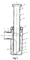
- the drain siphon 1 shown in Figure 1 has a housing 2, which preferably in Injection molding is made of plastic and in the one preferably separately manufactured insert 4 is inserted.
- insert 4 is from above a dip tube. 3 inserted.
- a nozzle 6 is integrally formed in an upper region, the horizontally away from the housing 2 and on which a here only partially shown Outlet pipe 7 is attached.
- This outlet pipe 7 leads to a not shown here Disposal line.
- the dip tube 3 is not at an upper end 8 to one here shown drain funnel, such as a sink or the like, connected.
- the water flowing out of the washbasin passes through a vertical one and for use 4 and to the housing 2 substantially coaxial channel 10 of the Immersion tube 3 to a mouth 11 at the bottom of the insert 4 and from there in a flow channel 18 and finally to the outlet, which through the nozzle. 6 is formed.
- the mouth 11 is below the water level of not here shown sealing water.
- the insert 4 has a lower edge 20, which rests tightly against a housing bottom 19 and with a lower guide wall 17, the interior of the housing 2 in said Flow channel 18 and a non-flowed space 21 divided.
- the sealing water is thus at least partially in the flow channel 18 but not in the space 21, which is separated from the flow channel 18 by said guide wall 17.
- a collar 14 (Fig. 2) is arranged, in which a Seal ring 15 is inserted, which the collar 14 relative to the housing. 2 seals.
- a plurality of retaining tongues 12 are formed, the rest on the upper edge of the housing 2 and which the insert 4 with the housing. 2 lock and position in a secure manner.
- Thread 13 is arranged, which for fastening a lid 5 on the insert 4 and serve to fix the dip tube 3.
- the lid 5 may be in the manner of a bayonet closure placed on the insert 4 and releasably secured by turning. in principle Here is also a screw cap conceivable.
- the dip tube 3 has a cylindrical outer wall 22 and a lower end 9, the is located immediately above the mouth 11 according to FIG.
- the dip tube 3 is to its longitudinal axis rotatable while the insert 4 is positioned against rotation in the housing 2 is.
- the lower end 9 of the dip tube 3 is at fully inserted Immersion tube 3 immediately above the mouth 11th
- the above-mentioned upper guide wall 17 is integrally formed on the outside of the insert 4 and extends as seen from the lower edge 20 on both sides upwards and vibrates Then, as shown in FIG. 4 arcuately around the insert 4 around.
- An outer edge 17a of the lower baffle 17 forms the transition to the nozzle 6, in particular the Fig. 3rd lets recognize.
- the edge 17a is located approximately in the area of the water level of the Sealing water.
Landscapes
- Engineering & Computer Science (AREA)
- Environmental & Geological Engineering (AREA)
- Health & Medical Sciences (AREA)
- Life Sciences & Earth Sciences (AREA)
- Hydrology & Water Resources (AREA)
- Public Health (AREA)
- Water Supply & Treatment (AREA)
- Sink And Installation For Waste Water (AREA)
- Sanitary Device For Flush Toilet (AREA)
Abstract
Description
- Figur 1
- ein Vertikalschnitt durch einen erfindungsgemässen Ablaufsiphon,
- Figur 2
- eine räumliche Ansicht eines Einsatzes,
- Figur 3
- ein Vertikalschnitt durch das Gehäuse mit einem Einsatz in Ansicht und
- Figur 4
- eine weitere Ansicht des Einsatzes.
- 1.
- Ablaufsiphon
- 2.
- Gehäuse
- 3.
- Tauchrohr
- 4.
- Einsatz
- 5.
- Deckel
- 6.
- Stutzen
- 7.
- Abgangsrohr
- 8.
- oberes Ende
- 9.
- unteres Ende
- 10.
- Kanal
- 11.
- Mündung
- 12.
- Haltezungen
- 13.
- Gewinde
- 14.
- Kragen
- 15.
- Dichtung
- 16.
- obere Leitwand
- 16a
- Rand
- 17.
- untere Leitwand
- 17a
- Rand
- 18.
- Strömungskanal
- 19.
- Gehäuseboden
- 20.
- unterer Rand
- 21.
- Raum
- 22.
- Aussenseite
Claims (15)
- Ablaufsiphon für eine Sanitäreinrichtung, beispielsweise ein Waschbecken, mit einem Gehäuse (2) zur Aufnahme von Sperrwasser, welches Gehäuse (2) ein Tauchrohr (3) aufnimmt und einen Auslass (6) besitzt und in dem ein Einsatz (4) angeordnet ist, der eine untere Mündung (11) aufweist, welche unterhalb des Wasserspiegels des Sperrwassers liegt, dadurch gekennzeichnet, dass zwischen der unteren Mündung (11) und dem genannten Auslass (6) ein durch Leitwände (16, 17) gebildeter direkter Strömungskanal (18) verläuft.
- Siphon nach Anspruchl, dadurch gekennzeichnet, dass der Strömungskanal (18) einen oberen Bereich aufweist, in welchem eine Aussenseite des Einsatzes (4) umströmt wird.
- Siphon nach Anspruch 1 oder 2, dadurch gekennzeichnet, dass der Strömungskanal (18) bezüglich des Auslasses (6) rückseitig nach oben verläuft.
- Siphon nach einem der Ansprüche 1 bis 3, dadurch gekennzeichnet, dass eine Leitwand (17) vorgesehen ist, welche den Strömungskanal (18) gegen einen leeren und unterhalb des Wasserspiegels liegenden Innenraum (21) des Gehäuses (2) trennt.
- Siphon nach einem der Ansprüche 1 bis 4, dadurch gekennzeichnet, dass sich die genannte Leitwand (17) nach unten bis zu einer Bodenwandung (19) des Gehäuses (2) erstreckt.
- Siphon nach Anspruch 4 oder 5, dadurch gekennzeichnet, dass die genannte Leitwand (17) an der Aussenseite des Einsatzes (4) angeformt ist.
- Siphon nach einem der Ansprüche 1 bis 6, dadurch gekennzeichnet, dass eine weitere obere Leitwand (16) vorgesehen ist, welche wenigstens bereichsweise an einem äusseren Rand (16a) an der Innenseite des Gehäuses (2) anliegt.
- Siphon nach einem der Ansprüche 1 bis 7, dadurch gekennzeichnet, dass der Einsatz (4) in Strömungsrichtung gesehen vor seiner unteren Mündung (11) mit dem Tauchrohr (3) einen koaxialen Kanal (10) bildet.
- Siphon nach einem der Ansprüche 1 bis 8, dadurch gekennzeichnet, dass die untere Mündung (11) des Einsatzes (4) bezüglich des Auslasses (6) nach rückwärts gerichtet ist.
- Siphon nach einem der Ansprüche 1 bis 9, dadurch gekennzeichnet, dass der Einsatz (4) passgenau in das Gehäuse (2) eingesetzt ist.
- Siphon nach einem der Ansprüche 1 bis 10, dadurch gekennzeichnet, dass in den Einsatz (4) von oben koaxial das untere Ende des Tauchrohres (3) eingesetzt ist.
- Siphon nach einem der Ansprüche 1 bis 11, dadurch gekennzeichnet, dass das Tauchrohr (3) so weit in den Einsatz (4) einschiebbar ist, dass ein unteres Ende (9) des Tauchrohres (3) sich unmittelbar über der Mündung (11) des Einsatzes (4) befindet.
- Siphon nach einem der Ansprüche 1 bis 12, dadurch gekennzeichnet, dass sich die Mündung (11) des Einsatzes (4) unmittelbar über einem Gehäuseboden (19) des Gehäuses (2) befindet.
- Siphon nach einem der Ansprüche 1 bis 13, dadurch gekennzeichnet, dass der Einsatz (4) verdrehsicher im Gehäuse (2) positioniert ist.
- Siphon nach einem der Ansprüche 1 bis 14, dadurch gekennzeichnet, dass die untere Leitwand (17') einseitig hochgezogen und/oder die obere Leitwand (16') heruntergezogen ist.
Priority Applications (2)
| Application Number | Priority Date | Filing Date | Title |
|---|---|---|---|
| EP04405015A EP1553232B1 (de) | 2004-01-08 | 2004-01-08 | Ablaufsiphon für eine Sanitäreinrichtung |
| AT04405015T ATE533898T1 (de) | 2004-01-08 | 2004-01-08 | Ablaufsiphon für eine sanitäreinrichtung |
Applications Claiming Priority (1)
| Application Number | Priority Date | Filing Date | Title |
|---|---|---|---|
| EP04405015A EP1553232B1 (de) | 2004-01-08 | 2004-01-08 | Ablaufsiphon für eine Sanitäreinrichtung |
Publications (2)
| Publication Number | Publication Date |
|---|---|
| EP1553232A1 true EP1553232A1 (de) | 2005-07-13 |
| EP1553232B1 EP1553232B1 (de) | 2011-11-16 |
Family
ID=34586029
Family Applications (1)
| Application Number | Title | Priority Date | Filing Date |
|---|---|---|---|
| EP04405015A Expired - Lifetime EP1553232B1 (de) | 2004-01-08 | 2004-01-08 | Ablaufsiphon für eine Sanitäreinrichtung |
Country Status (2)
| Country | Link |
|---|---|
| EP (1) | EP1553232B1 (de) |
| AT (1) | ATE533898T1 (de) |
Cited By (1)
| Publication number | Priority date | Publication date | Assignee | Title |
|---|---|---|---|---|
| EP1775395A1 (de) * | 2005-10-11 | 2007-04-18 | Geberit Technik Ag | Ablaufarmatur für sanitäre Anlagen |
Citations (3)
| Publication number | Priority date | Publication date | Assignee | Title |
|---|---|---|---|---|
| EP0727532A1 (de) | 1995-02-14 | 1996-08-21 | Friedrich Grohe Aktiengesellschaft | Ablaufeinrichtung |
| FR2771431A1 (fr) * | 1997-11-24 | 1999-05-28 | Sanitaire Accessoires Services | Ensemble de vidage pour appareils sanitaires |
| EP1227191A2 (de) | 2001-01-27 | 2002-07-31 | Hansgrohe AG | Ablaufsiphon für Waschbecken oder dergleichen |
-
2004
- 2004-01-08 EP EP04405015A patent/EP1553232B1/de not_active Expired - Lifetime
- 2004-01-08 AT AT04405015T patent/ATE533898T1/de active
Patent Citations (3)
| Publication number | Priority date | Publication date | Assignee | Title |
|---|---|---|---|---|
| EP0727532A1 (de) | 1995-02-14 | 1996-08-21 | Friedrich Grohe Aktiengesellschaft | Ablaufeinrichtung |
| FR2771431A1 (fr) * | 1997-11-24 | 1999-05-28 | Sanitaire Accessoires Services | Ensemble de vidage pour appareils sanitaires |
| EP1227191A2 (de) | 2001-01-27 | 2002-07-31 | Hansgrohe AG | Ablaufsiphon für Waschbecken oder dergleichen |
Cited By (1)
| Publication number | Priority date | Publication date | Assignee | Title |
|---|---|---|---|---|
| EP1775395A1 (de) * | 2005-10-11 | 2007-04-18 | Geberit Technik Ag | Ablaufarmatur für sanitäre Anlagen |
Also Published As
| Publication number | Publication date |
|---|---|
| ATE533898T1 (de) | 2011-12-15 |
| EP1553232B1 (de) | 2011-11-16 |
Similar Documents
| Publication | Publication Date | Title |
|---|---|---|
| EP2045403B1 (de) | Ablaufgarnitur mit integriertem Überlauf | |
| EP2453065B1 (de) | Ablaufgarnitur mit verdeckt positionierbarem Überlauf | |
| DE69924457T2 (de) | Behälter mit verbesserten Giesseigenschaften | |
| EP3495576A2 (de) | System aus einem geruchsverschluss und einem aufnahmekörper sowie ein geruchsverschluss | |
| EP0476402A2 (de) | Anordnung zur Befestigung einer Handbrause | |
| DE69815385T2 (de) | Wasserabführungseinrichtung | |
| EP0446179A1 (de) | Doppelrohrverbindung an Kunststoffrohren | |
| DE4206903A1 (de) | Ablaufarmatur fuer brausebecken oder spuelbecken | |
| EP3825480A1 (de) | Spülwasserverteiler | |
| EP3260607B1 (de) | Siphon | |
| DE102007025595A1 (de) | Füllventil | |
| DE20019328U1 (de) | Waschbeckenüberlauf | |
| EP1553232B1 (de) | Ablaufsiphon für eine Sanitäreinrichtung | |
| EP3567170A1 (de) | Ablaufarmatur für eine dusch- oder badewanne | |
| EP1798352A1 (de) | Ablauf für sanitäre Apparate | |
| EP1775395B1 (de) | Ablaufarmatur für sanitäre Anlagen | |
| DE102006021801B4 (de) | Sanitäre Auslaufeinheit | |
| DE2522425C3 (de) | Bodenablauf mit Genichverschluß für Abwasserbehälter | |
| DE202008015030U1 (de) | Raumsparsifon | |
| DE102023123249A1 (de) | Anordnungssystem zur Anordnung eines Spülbehälters eines Sanitärausstattungsgegenstandes | |
| DE10204683B4 (de) | Becken | |
| DE29712972U1 (de) | Ablaufarmatur, insbesondere für eine Duschwanne | |
| DE3940741A1 (de) | Ausgiessverschluss mit belueftung | |
| DE202008006611U1 (de) | Ablaufgarnitur für Wasch- oder Spülbecken | |
| EP3825479A1 (de) | Spülwasserverteiler |
Legal Events
| Date | Code | Title | Description |
|---|---|---|---|
| PUAI | Public reference made under article 153(3) epc to a published international application that has entered the european phase |
Free format text: ORIGINAL CODE: 0009012 |
|
| AK | Designated contracting states |
Kind code of ref document: A1 Designated state(s): AT BE BG CH CY CZ DE DK EE ES FI FR GB GR HU IE IT LI LU MC NL PT RO SE SI SK TR |
|
| AX | Request for extension of the european patent |
Extension state: AL LT LV MK |
|
| 17P | Request for examination filed |
Effective date: 20050802 |
|
| AKX | Designation fees paid |
Designated state(s): AT BE BG CH CY CZ DE DK EE ES FI FR GB GR HU IE IT LI LU MC NL PT RO SE SI SK TR |
|
| 17Q | First examination report despatched |
Effective date: 20080407 |
|
| RAP1 | Party data changed (applicant data changed or rights of an application transferred) |
Owner name: GEBERIT INTERNATIONAL AG |
|
| GRAP | Despatch of communication of intention to grant a patent |
Free format text: ORIGINAL CODE: EPIDOSNIGR1 |
|
| GRAS | Grant fee paid |
Free format text: ORIGINAL CODE: EPIDOSNIGR3 |
|
| GRAA | (expected) grant |
Free format text: ORIGINAL CODE: 0009210 |
|
| AK | Designated contracting states |
Kind code of ref document: B1 Designated state(s): AT BE BG CH CY CZ DE DK EE ES FI FR GB GR HU IE IT LI LU MC NL PT RO SE SI SK TR |
|
| REG | Reference to a national code |
Ref country code: GB Ref legal event code: FG4D Free format text: NOT ENGLISH |
|
| REG | Reference to a national code |
Ref country code: CH Ref legal event code: EP Ref country code: CH Ref legal event code: NV Representative=s name: ISLER & PEDRAZZINI AG |
|
| REG | Reference to a national code |
Ref country code: IE Ref legal event code: FG4D Free format text: LANGUAGE OF EP DOCUMENT: GERMAN |
|
| REG | Reference to a national code |
Ref country code: NL Ref legal event code: T3 |
|
| REG | Reference to a national code |
Ref country code: DE Ref legal event code: R096 Ref document number: 502004013065 Country of ref document: DE Effective date: 20120223 |
|
| PG25 | Lapsed in a contracting state [announced via postgrant information from national office to epo] |
Ref country code: PT Free format text: LAPSE BECAUSE OF FAILURE TO SUBMIT A TRANSLATION OF THE DESCRIPTION OR TO PAY THE FEE WITHIN THE PRESCRIBED TIME-LIMIT Effective date: 20120316 Ref country code: SI Free format text: LAPSE BECAUSE OF FAILURE TO SUBMIT A TRANSLATION OF THE DESCRIPTION OR TO PAY THE FEE WITHIN THE PRESCRIBED TIME-LIMIT Effective date: 20111116 Ref country code: SE Free format text: LAPSE BECAUSE OF FAILURE TO SUBMIT A TRANSLATION OF THE DESCRIPTION OR TO PAY THE FEE WITHIN THE PRESCRIBED TIME-LIMIT Effective date: 20111116 Ref country code: GR Free format text: LAPSE BECAUSE OF FAILURE TO SUBMIT A TRANSLATION OF THE DESCRIPTION OR TO PAY THE FEE WITHIN THE PRESCRIBED TIME-LIMIT Effective date: 20120217 |
|
| REG | Reference to a national code |
Ref country code: IE Ref legal event code: FD4D |
|
| PG25 | Lapsed in a contracting state [announced via postgrant information from national office to epo] |
Ref country code: CY Free format text: LAPSE BECAUSE OF FAILURE TO SUBMIT A TRANSLATION OF THE DESCRIPTION OR TO PAY THE FEE WITHIN THE PRESCRIBED TIME-LIMIT Effective date: 20111116 |
|
| PG25 | Lapsed in a contracting state [announced via postgrant information from national office to epo] |
Ref country code: IE Free format text: LAPSE BECAUSE OF FAILURE TO SUBMIT A TRANSLATION OF THE DESCRIPTION OR TO PAY THE FEE WITHIN THE PRESCRIBED TIME-LIMIT Effective date: 20111116 Ref country code: BG Free format text: LAPSE BECAUSE OF FAILURE TO SUBMIT A TRANSLATION OF THE DESCRIPTION OR TO PAY THE FEE WITHIN THE PRESCRIBED TIME-LIMIT Effective date: 20120216 Ref country code: DK Free format text: LAPSE BECAUSE OF FAILURE TO SUBMIT A TRANSLATION OF THE DESCRIPTION OR TO PAY THE FEE WITHIN THE PRESCRIBED TIME-LIMIT Effective date: 20111116 Ref country code: EE Free format text: LAPSE BECAUSE OF FAILURE TO SUBMIT A TRANSLATION OF THE DESCRIPTION OR TO PAY THE FEE WITHIN THE PRESCRIBED TIME-LIMIT Effective date: 20111116 Ref country code: SK Free format text: LAPSE BECAUSE OF FAILURE TO SUBMIT A TRANSLATION OF THE DESCRIPTION OR TO PAY THE FEE WITHIN THE PRESCRIBED TIME-LIMIT Effective date: 20111116 Ref country code: CZ Free format text: LAPSE BECAUSE OF FAILURE TO SUBMIT A TRANSLATION OF THE DESCRIPTION OR TO PAY THE FEE WITHIN THE PRESCRIBED TIME-LIMIT Effective date: 20111116 |
|
| PG25 | Lapsed in a contracting state [announced via postgrant information from national office to epo] |
Ref country code: MC Free format text: LAPSE BECAUSE OF NON-PAYMENT OF DUE FEES Effective date: 20120131 Ref country code: RO Free format text: LAPSE BECAUSE OF FAILURE TO SUBMIT A TRANSLATION OF THE DESCRIPTION OR TO PAY THE FEE WITHIN THE PRESCRIBED TIME-LIMIT Effective date: 20111116 |
|
| PLBE | No opposition filed within time limit |
Free format text: ORIGINAL CODE: 0009261 |
|
| STAA | Information on the status of an ep patent application or granted ep patent |
Free format text: STATUS: NO OPPOSITION FILED WITHIN TIME LIMIT |
|
| 26N | No opposition filed |
Effective date: 20120817 |
|
| GBPC | Gb: european patent ceased through non-payment of renewal fee |
Effective date: 20120216 |
|
| REG | Reference to a national code |
Ref country code: DE Ref legal event code: R097 Ref document number: 502004013065 Country of ref document: DE Effective date: 20120817 |
|
| PG25 | Lapsed in a contracting state [announced via postgrant information from national office to epo] |
Ref country code: GB Free format text: LAPSE BECAUSE OF NON-PAYMENT OF DUE FEES Effective date: 20120216 |
|
| PG25 | Lapsed in a contracting state [announced via postgrant information from national office to epo] |
Ref country code: ES Free format text: LAPSE BECAUSE OF FAILURE TO SUBMIT A TRANSLATION OF THE DESCRIPTION OR TO PAY THE FEE WITHIN THE PRESCRIBED TIME-LIMIT Effective date: 20120227 |
|
| PG25 | Lapsed in a contracting state [announced via postgrant information from national office to epo] |
Ref country code: FI Free format text: LAPSE BECAUSE OF FAILURE TO SUBMIT A TRANSLATION OF THE DESCRIPTION OR TO PAY THE FEE WITHIN THE PRESCRIBED TIME-LIMIT Effective date: 20111116 |
|
| REG | Reference to a national code |
Ref country code: DE Ref legal event code: R082 Ref document number: 502004013065 Country of ref document: DE Representative=s name: HOEGER, STELLRECHT & PARTNER PATENTANWAELTE, DE Ref country code: DE Ref legal event code: R082 Ref document number: 502004013065 Country of ref document: DE Representative=s name: HOEGER, STELLRECHT & PARTNER PATENTANWAELTE MB, DE |
|
| PG25 | Lapsed in a contracting state [announced via postgrant information from national office to epo] |
Ref country code: TR Free format text: LAPSE BECAUSE OF FAILURE TO SUBMIT A TRANSLATION OF THE DESCRIPTION OR TO PAY THE FEE WITHIN THE PRESCRIBED TIME-LIMIT Effective date: 20111116 |
|
| PG25 | Lapsed in a contracting state [announced via postgrant information from national office to epo] |
Ref country code: LU Free format text: LAPSE BECAUSE OF NON-PAYMENT OF DUE FEES Effective date: 20120108 |
|
| PG25 | Lapsed in a contracting state [announced via postgrant information from national office to epo] |
Ref country code: HU Free format text: LAPSE BECAUSE OF FAILURE TO SUBMIT A TRANSLATION OF THE DESCRIPTION OR TO PAY THE FEE WITHIN THE PRESCRIBED TIME-LIMIT Effective date: 20040108 |
|
| REG | Reference to a national code |
Ref country code: FR Ref legal event code: PLFP Year of fee payment: 12 |
|
| PGFP | Annual fee paid to national office [announced via postgrant information from national office to epo] |
Ref country code: NL Payment date: 20150129 Year of fee payment: 12 |
|
| PGFP | Annual fee paid to national office [announced via postgrant information from national office to epo] |
Ref country code: FR Payment date: 20150122 Year of fee payment: 12 |
|
| PGFP | Annual fee paid to national office [announced via postgrant information from national office to epo] |
Ref country code: BE Payment date: 20150121 Year of fee payment: 12 |
|
| REG | Reference to a national code |
Ref country code: DE Ref legal event code: R082 Ref document number: 502004013065 Country of ref document: DE Representative=s name: HOEGER, STELLRECHT & PARTNER PATENTANWAELTE MB, DE |
|
| PG25 | Lapsed in a contracting state [announced via postgrant information from national office to epo] |
Ref country code: BE Free format text: LAPSE BECAUSE OF NON-PAYMENT OF DUE FEES Effective date: 20160131 |
|
| REG | Reference to a national code |
Ref country code: NL Ref legal event code: MM Effective date: 20160201 |
|
| REG | Reference to a national code |
Ref country code: FR Ref legal event code: ST Effective date: 20160930 |
|
| PG25 | Lapsed in a contracting state [announced via postgrant information from national office to epo] |
Ref country code: NL Free format text: LAPSE BECAUSE OF NON-PAYMENT OF DUE FEES Effective date: 20160201 Ref country code: FR Free format text: LAPSE BECAUSE OF NON-PAYMENT OF DUE FEES Effective date: 20160201 |
|
| PGFP | Annual fee paid to national office [announced via postgrant information from national office to epo] |
Ref country code: DE Payment date: 20180122 Year of fee payment: 15 Ref country code: CH Payment date: 20180111 Year of fee payment: 15 |
|
| PGFP | Annual fee paid to national office [announced via postgrant information from national office to epo] |
Ref country code: AT Payment date: 20180122 Year of fee payment: 15 Ref country code: IT Payment date: 20180129 Year of fee payment: 15 |
|
| REG | Reference to a national code |
Ref country code: DE Ref legal event code: R082 Ref document number: 502004013065 Country of ref document: DE Representative=s name: HOEGER, STELLRECHT & PARTNER PATENTANWAELTE MB, DE |
|
| REG | Reference to a national code |
Ref country code: DE Ref legal event code: R119 Ref document number: 502004013065 Country of ref document: DE |
|
| REG | Reference to a national code |
Ref country code: CH Ref legal event code: PL |
|
| REG | Reference to a national code |
Ref country code: AT Ref legal event code: MM01 Ref document number: 533898 Country of ref document: AT Kind code of ref document: T Effective date: 20190108 |
|
| PG25 | Lapsed in a contracting state [announced via postgrant information from national office to epo] |
Ref country code: DE Free format text: LAPSE BECAUSE OF NON-PAYMENT OF DUE FEES Effective date: 20190801 |
|
| PG25 | Lapsed in a contracting state [announced via postgrant information from national office to epo] |
Ref country code: CH Free format text: LAPSE BECAUSE OF NON-PAYMENT OF DUE FEES Effective date: 20190131 Ref country code: AT Free format text: LAPSE BECAUSE OF NON-PAYMENT OF DUE FEES Effective date: 20190108 Ref country code: LI Free format text: LAPSE BECAUSE OF NON-PAYMENT OF DUE FEES Effective date: 20190131 |
|
| PG25 | Lapsed in a contracting state [announced via postgrant information from national office to epo] |
Ref country code: IT Free format text: LAPSE BECAUSE OF NON-PAYMENT OF DUE FEES Effective date: 20190108 |