EP1550835B1 - Kreuzstromwärmetauscher für Kondensationswäschetrockner - Google Patents
Kreuzstromwärmetauscher für Kondensationswäschetrockner Download PDFInfo
- Publication number
- EP1550835B1 EP1550835B1 EP04400054A EP04400054A EP1550835B1 EP 1550835 B1 EP1550835 B1 EP 1550835B1 EP 04400054 A EP04400054 A EP 04400054A EP 04400054 A EP04400054 A EP 04400054A EP 1550835 B1 EP1550835 B1 EP 1550835B1
- Authority
- EP
- European Patent Office
- Prior art keywords
- heat exchanger
- flange
- exchanger plates
- cross flow
- flow heat
- Prior art date
- Legal status (The legal status is an assumption and is not a legal conclusion. Google has not performed a legal analysis and makes no representation as to the accuracy of the status listed.)
- Expired - Lifetime
Links
- 238000003466 welding Methods 0.000 claims description 18
- 238000000034 method Methods 0.000 claims description 14
- 239000000463 material Substances 0.000 claims description 11
- 238000001816 cooling Methods 0.000 claims description 9
- 239000004743 Polypropylene Substances 0.000 claims description 6
- 239000000654 additive Substances 0.000 claims description 6
- 230000000996 additive effect Effects 0.000 claims description 6
- -1 polypropylene Polymers 0.000 claims description 6
- 229920001155 polypropylene Polymers 0.000 claims description 6
- 239000012815 thermoplastic material Substances 0.000 claims description 6
- 238000004519 manufacturing process Methods 0.000 claims description 4
- 230000006698 induction Effects 0.000 claims description 3
- 230000002093 peripheral effect Effects 0.000 claims 4
- 239000012809 cooling fluid Substances 0.000 claims 2
- 239000011347 resin Substances 0.000 description 6
- 229920005989 resin Polymers 0.000 description 6
- 238000005304 joining Methods 0.000 description 5
- 238000002156 mixing Methods 0.000 description 5
- 238000009833 condensation Methods 0.000 description 4
- 230000005494 condensation Effects 0.000 description 4
- 239000000853 adhesive Substances 0.000 description 2
- 230000001070 adhesive effect Effects 0.000 description 2
- 238000005266 casting Methods 0.000 description 2
- 239000002131 composite material Substances 0.000 description 1
- 239000000109 continuous material Substances 0.000 description 1
- 239000007788 liquid Substances 0.000 description 1
- 238000002844 melting Methods 0.000 description 1
- 230000008018 melting Effects 0.000 description 1
- 239000000203 mixture Substances 0.000 description 1
- 239000012768 molten material Substances 0.000 description 1
- 150000002825 nitriles Chemical class 0.000 description 1
- 239000002245 particle Substances 0.000 description 1
- 239000000843 powder Substances 0.000 description 1
- 238000004064 recycling Methods 0.000 description 1
- 238000007711 solidification Methods 0.000 description 1
- 230000008023 solidification Effects 0.000 description 1
- 238000003856 thermoforming Methods 0.000 description 1
- 229920001169 thermoplastic Polymers 0.000 description 1
- 239000004416 thermosoftening plastic Substances 0.000 description 1
Images
Classifications
-
- F—MECHANICAL ENGINEERING; LIGHTING; HEATING; WEAPONS; BLASTING
- F28—HEAT EXCHANGE IN GENERAL
- F28D—HEAT-EXCHANGE APPARATUS, NOT PROVIDED FOR IN ANOTHER SUBCLASS, IN WHICH THE HEAT-EXCHANGE MEDIA DO NOT COME INTO DIRECT CONTACT
- F28D9/00—Heat-exchange apparatus having stationary plate-like or laminated conduit assemblies for both heat-exchange media, the media being in contact with different sides of a conduit wall
- F28D9/0031—Heat-exchange apparatus having stationary plate-like or laminated conduit assemblies for both heat-exchange media, the media being in contact with different sides of a conduit wall the conduits for one heat-exchange medium being formed by paired plates touching each other
-
- B—PERFORMING OPERATIONS; TRANSPORTING
- B29—WORKING OF PLASTICS; WORKING OF SUBSTANCES IN A PLASTIC STATE IN GENERAL
- B29C—SHAPING OR JOINING OF PLASTICS; SHAPING OF MATERIAL IN A PLASTIC STATE, NOT OTHERWISE PROVIDED FOR; AFTER-TREATMENT OF THE SHAPED PRODUCTS, e.g. REPAIRING
- B29C65/00—Joining or sealing of preformed parts, e.g. welding of plastics materials; Apparatus therefor
- B29C65/02—Joining or sealing of preformed parts, e.g. welding of plastics materials; Apparatus therefor by heating, with or without pressure
-
- B—PERFORMING OPERATIONS; TRANSPORTING
- B29—WORKING OF PLASTICS; WORKING OF SUBSTANCES IN A PLASTIC STATE IN GENERAL
- B29C—SHAPING OR JOINING OF PLASTICS; SHAPING OF MATERIAL IN A PLASTIC STATE, NOT OTHERWISE PROVIDED FOR; AFTER-TREATMENT OF THE SHAPED PRODUCTS, e.g. REPAIRING
- B29C66/00—General aspects of processes or apparatus for joining preformed parts
- B29C66/50—General aspects of joining tubular articles; General aspects of joining long products, i.e. bars or profiled elements; General aspects of joining single elements to tubular articles, hollow articles or bars; General aspects of joining several hollow-preforms to form hollow or tubular articles
- B29C66/51—Joining tubular articles, profiled elements or bars; Joining single elements to tubular articles, hollow articles or bars; Joining several hollow-preforms to form hollow or tubular articles
- B29C66/53—Joining single elements to tubular articles, hollow articles or bars
- B29C66/534—Joining single elements to open ends of tubular or hollow articles or to the ends of bars
- B29C66/5346—Joining single elements to open ends of tubular or hollow articles or to the ends of bars said single elements being substantially flat
-
- F—MECHANICAL ENGINEERING; LIGHTING; HEATING; WEAPONS; BLASTING
- F28—HEAT EXCHANGE IN GENERAL
- F28F—DETAILS OF HEAT-EXCHANGE AND HEAT-TRANSFER APPARATUS, OF GENERAL APPLICATION
- F28F21/00—Constructions of heat-exchange apparatus characterised by the selection of particular materials
- F28F21/06—Constructions of heat-exchange apparatus characterised by the selection of particular materials of plastics material
- F28F21/065—Constructions of heat-exchange apparatus characterised by the selection of particular materials of plastics material the heat-exchange apparatus employing plate-like or laminated conduits
-
- F—MECHANICAL ENGINEERING; LIGHTING; HEATING; WEAPONS; BLASTING
- F28—HEAT EXCHANGE IN GENERAL
- F28F—DETAILS OF HEAT-EXCHANGE AND HEAT-TRANSFER APPARATUS, OF GENERAL APPLICATION
- F28F9/00—Casings; Header boxes; Auxiliary supports for elements; Auxiliary members within casings
- F28F9/02—Header boxes; End plates
- F28F9/04—Arrangements for sealing elements into header boxes or end plates
- F28F9/16—Arrangements for sealing elements into header boxes or end plates by permanent joints, e.g. by rolling
- F28F9/18—Arrangements for sealing elements into header boxes or end plates by permanent joints, e.g. by rolling by welding
- F28F9/187—Arrangements for sealing elements into header boxes or end plates by permanent joints, e.g. by rolling by welding at least one of the parts being non-metallic, e.g. heat-sealing plastic elements
-
- B—PERFORMING OPERATIONS; TRANSPORTING
- B29—WORKING OF PLASTICS; WORKING OF SUBSTANCES IN A PLASTIC STATE IN GENERAL
- B29C—SHAPING OR JOINING OF PLASTICS; SHAPING OF MATERIAL IN A PLASTIC STATE, NOT OTHERWISE PROVIDED FOR; AFTER-TREATMENT OF THE SHAPED PRODUCTS, e.g. REPAIRING
- B29C65/00—Joining or sealing of preformed parts, e.g. welding of plastics materials; Apparatus therefor
- B29C65/02—Joining or sealing of preformed parts, e.g. welding of plastics materials; Apparatus therefor by heating, with or without pressure
- B29C65/06—Joining or sealing of preformed parts, e.g. welding of plastics materials; Apparatus therefor by heating, with or without pressure using friction, e.g. spin welding
-
- B—PERFORMING OPERATIONS; TRANSPORTING
- B29—WORKING OF PLASTICS; WORKING OF SUBSTANCES IN A PLASTIC STATE IN GENERAL
- B29C—SHAPING OR JOINING OF PLASTICS; SHAPING OF MATERIAL IN A PLASTIC STATE, NOT OTHERWISE PROVIDED FOR; AFTER-TREATMENT OF THE SHAPED PRODUCTS, e.g. REPAIRING
- B29C65/00—Joining or sealing of preformed parts, e.g. welding of plastics materials; Apparatus therefor
- B29C65/02—Joining or sealing of preformed parts, e.g. welding of plastics materials; Apparatus therefor by heating, with or without pressure
- B29C65/08—Joining or sealing of preformed parts, e.g. welding of plastics materials; Apparatus therefor by heating, with or without pressure using ultrasonic vibrations
-
- B—PERFORMING OPERATIONS; TRANSPORTING
- B29—WORKING OF PLASTICS; WORKING OF SUBSTANCES IN A PLASTIC STATE IN GENERAL
- B29C—SHAPING OR JOINING OF PLASTICS; SHAPING OF MATERIAL IN A PLASTIC STATE, NOT OTHERWISE PROVIDED FOR; AFTER-TREATMENT OF THE SHAPED PRODUCTS, e.g. REPAIRING
- B29C65/00—Joining or sealing of preformed parts, e.g. welding of plastics materials; Apparatus therefor
- B29C65/02—Joining or sealing of preformed parts, e.g. welding of plastics materials; Apparatus therefor by heating, with or without pressure
- B29C65/14—Joining or sealing of preformed parts, e.g. welding of plastics materials; Apparatus therefor by heating, with or without pressure using wave energy, i.e. electromagnetic radiation, or particle radiation
- B29C65/16—Laser beams
-
- B—PERFORMING OPERATIONS; TRANSPORTING
- B29—WORKING OF PLASTICS; WORKING OF SUBSTANCES IN A PLASTIC STATE IN GENERAL
- B29C—SHAPING OR JOINING OF PLASTICS; SHAPING OF MATERIAL IN A PLASTIC STATE, NOT OTHERWISE PROVIDED FOR; AFTER-TREATMENT OF THE SHAPED PRODUCTS, e.g. REPAIRING
- B29C65/00—Joining or sealing of preformed parts, e.g. welding of plastics materials; Apparatus therefor
- B29C65/02—Joining or sealing of preformed parts, e.g. welding of plastics materials; Apparatus therefor by heating, with or without pressure
- B29C65/34—Joining or sealing of preformed parts, e.g. welding of plastics materials; Apparatus therefor by heating, with or without pressure using heated elements which remain in the joint, e.g. "verlorenes Schweisselement"
-
- B—PERFORMING OPERATIONS; TRANSPORTING
- B29—WORKING OF PLASTICS; WORKING OF SUBSTANCES IN A PLASTIC STATE IN GENERAL
- B29C—SHAPING OR JOINING OF PLASTICS; SHAPING OF MATERIAL IN A PLASTIC STATE, NOT OTHERWISE PROVIDED FOR; AFTER-TREATMENT OF THE SHAPED PRODUCTS, e.g. REPAIRING
- B29C65/00—Joining or sealing of preformed parts, e.g. welding of plastics materials; Apparatus therefor
- B29C65/02—Joining or sealing of preformed parts, e.g. welding of plastics materials; Apparatus therefor by heating, with or without pressure
- B29C65/34—Joining or sealing of preformed parts, e.g. welding of plastics materials; Apparatus therefor by heating, with or without pressure using heated elements which remain in the joint, e.g. "verlorenes Schweisselement"
- B29C65/36—Joining or sealing of preformed parts, e.g. welding of plastics materials; Apparatus therefor by heating, with or without pressure using heated elements which remain in the joint, e.g. "verlorenes Schweisselement" heated by induction
- B29C65/3604—Joining or sealing of preformed parts, e.g. welding of plastics materials; Apparatus therefor by heating, with or without pressure using heated elements which remain in the joint, e.g. "verlorenes Schweisselement" heated by induction characterised by the type of elements heated by induction which remain in the joint
- B29C65/3608—Joining or sealing of preformed parts, e.g. welding of plastics materials; Apparatus therefor by heating, with or without pressure using heated elements which remain in the joint, e.g. "verlorenes Schweisselement" heated by induction characterised by the type of elements heated by induction which remain in the joint comprising single particles, e.g. fillers or discontinuous fibre-reinforcements
- B29C65/3612—Joining or sealing of preformed parts, e.g. welding of plastics materials; Apparatus therefor by heating, with or without pressure using heated elements which remain in the joint, e.g. "verlorenes Schweisselement" heated by induction characterised by the type of elements heated by induction which remain in the joint comprising single particles, e.g. fillers or discontinuous fibre-reinforcements comprising fillers
-
- B—PERFORMING OPERATIONS; TRANSPORTING
- B29—WORKING OF PLASTICS; WORKING OF SUBSTANCES IN A PLASTIC STATE IN GENERAL
- B29C—SHAPING OR JOINING OF PLASTICS; SHAPING OF MATERIAL IN A PLASTIC STATE, NOT OTHERWISE PROVIDED FOR; AFTER-TREATMENT OF THE SHAPED PRODUCTS, e.g. REPAIRING
- B29C65/00—Joining or sealing of preformed parts, e.g. welding of plastics materials; Apparatus therefor
- B29C65/48—Joining or sealing of preformed parts, e.g. welding of plastics materials; Apparatus therefor using adhesives, i.e. using supplementary joining material; solvent bonding
-
- B—PERFORMING OPERATIONS; TRANSPORTING
- B29—WORKING OF PLASTICS; WORKING OF SUBSTANCES IN A PLASTIC STATE IN GENERAL
- B29C—SHAPING OR JOINING OF PLASTICS; SHAPING OF MATERIAL IN A PLASTIC STATE, NOT OTHERWISE PROVIDED FOR; AFTER-TREATMENT OF THE SHAPED PRODUCTS, e.g. REPAIRING
- B29C66/00—General aspects of processes or apparatus for joining preformed parts
- B29C66/01—General aspects dealing with the joint area or with the area to be joined
- B29C66/05—Particular design of joint configurations
- B29C66/10—Particular design of joint configurations particular design of the joint cross-sections
- B29C66/12—Joint cross-sections combining only two joint-segments; Tongue and groove joints; Tenon and mortise joints; Stepped joint cross-sections
- B29C66/124—Tongue and groove joints
- B29C66/1244—Tongue and groove joints characterised by the male part, i.e. the part comprising the tongue
- B29C66/12441—Tongue and groove joints characterised by the male part, i.e. the part comprising the tongue being a single wall
-
- B—PERFORMING OPERATIONS; TRANSPORTING
- B29—WORKING OF PLASTICS; WORKING OF SUBSTANCES IN A PLASTIC STATE IN GENERAL
- B29C—SHAPING OR JOINING OF PLASTICS; SHAPING OF MATERIAL IN A PLASTIC STATE, NOT OTHERWISE PROVIDED FOR; AFTER-TREATMENT OF THE SHAPED PRODUCTS, e.g. REPAIRING
- B29C66/00—General aspects of processes or apparatus for joining preformed parts
- B29C66/70—General aspects of processes or apparatus for joining preformed parts characterised by the composition, physical properties or the structure of the material of the parts to be joined; Joining with non-plastics material
- B29C66/71—General aspects of processes or apparatus for joining preformed parts characterised by the composition, physical properties or the structure of the material of the parts to be joined; Joining with non-plastics material characterised by the composition of the plastics material of the parts to be joined
-
- B—PERFORMING OPERATIONS; TRANSPORTING
- B29—WORKING OF PLASTICS; WORKING OF SUBSTANCES IN A PLASTIC STATE IN GENERAL
- B29K—INDEXING SCHEME ASSOCIATED WITH SUBCLASSES B29B, B29C OR B29D, RELATING TO MOULDING MATERIALS OR TO MATERIALS FOR MOULDS, REINFORCEMENTS, FILLERS OR PREFORMED PARTS, e.g. INSERTS
- B29K2023/00—Use of polyalkenes or derivatives thereof as moulding material
- B29K2023/10—Polymers of propylene
- B29K2023/12—PP, i.e. polypropylene
-
- B—PERFORMING OPERATIONS; TRANSPORTING
- B29—WORKING OF PLASTICS; WORKING OF SUBSTANCES IN A PLASTIC STATE IN GENERAL
- B29K—INDEXING SCHEME ASSOCIATED WITH SUBCLASSES B29B, B29C OR B29D, RELATING TO MOULDING MATERIALS OR TO MATERIALS FOR MOULDS, REINFORCEMENTS, FILLERS OR PREFORMED PARTS, e.g. INSERTS
- B29K2105/00—Condition, form or state of moulded material or of the material to be shaped
- B29K2105/26—Scrap or recycled material
-
- B—PERFORMING OPERATIONS; TRANSPORTING
- B29—WORKING OF PLASTICS; WORKING OF SUBSTANCES IN A PLASTIC STATE IN GENERAL
- B29L—INDEXING SCHEME ASSOCIATED WITH SUBCLASS B29C, RELATING TO PARTICULAR ARTICLES
- B29L2031/00—Other particular articles
- B29L2031/18—Heat-exchangers or parts thereof
-
- F—MECHANICAL ENGINEERING; LIGHTING; HEATING; WEAPONS; BLASTING
- F28—HEAT EXCHANGE IN GENERAL
- F28F—DETAILS OF HEAT-EXCHANGE AND HEAT-TRANSFER APPARATUS, OF GENERAL APPLICATION
- F28F2275/00—Fastening; Joining
- F28F2275/06—Fastening; Joining by welding
- F28F2275/065—Fastening; Joining by welding by ultrasonic or vibration welding
-
- F—MECHANICAL ENGINEERING; LIGHTING; HEATING; WEAPONS; BLASTING
- F28—HEAT EXCHANGE IN GENERAL
- F28F—DETAILS OF HEAT-EXCHANGE AND HEAT-TRANSFER APPARATUS, OF GENERAL APPLICATION
- F28F2275/00—Fastening; Joining
- F28F2275/06—Fastening; Joining by welding
- F28F2275/067—Fastening; Joining by welding by laser welding
Definitions
- the invention relates to a cross-flow heat exchanger for condensation clothes dryer, with a plurality of heat exchanger plates made of thermoplastic material, which are layered parallel to each other and form or limit channels for moist air and cooling air, with at least one consisting of thermoplastic material flange to which the heat exchanger plates are fixed.
- the invention also relates to a method for producing a cross-flow heat exchanger for condensation clothes dryer.
- Such a cross-flow heat exchanger is from the EP-A-1 106 729 , of the EP-A-0 982 427 and the DE-U-91 05 079 known.
- cooling air is used as the process air, which is passed through the heat exchanger.
- This cooling air cools the warm humid air that flows through the heat exchanger across the cooling air.
- By cooling the warm humid air moisture can be deposited, which is reflected on the surfaces of the heat exchanger plates and can drain as condensate.
- the generic EP-A-1106729 describes the preamble of claims 1 and 6.
- the heat exchanger plates are held on a flange, so that an overall cube or cuboid structure is created.
- the heat exchanger plates can be fixed individually or in pairs on the flange.
- the heat exchanger plates can also be connected to each other, for example by additional webs.
- the present invention seeks to provide a cross-flow heat exchanger in which the flange can be easily and yet joined for the strength of subsequent welding advantage with a variety of heat exchanger plates.
- the heat exchanger plates and the flange can be joined together directly, that is without the use of cast resin.
- the weld joint can be produced inexpensively and also ensures the required to avoid leakage leakage between heat exchanger plates and flange.
- the flange has receiving sections for edge sections of the heat exchanger plates on.
- the relative position of heat exchanger plates and flange can be defined. This is for an easy handling of the heat exchanger plates advantageous, especially if they are film-like and thus limp formed.
- the receiving portions may be web-shaped, in particular conical, formed, so that they can be easily inserted between the heat exchanger plates before the edge portions and the receiving portions are joined together by one of the welding methods described.
- the receiving portions may also be formed as apertures, so that edge portions of the heat exchanger plates, the apertures cross-taking, are included in these. This also allows a good stability of the composite of heat exchanger plates and flange can be achieved.
- the welded connection can be produced for example by ultrasonic welding. Due to the very short welding times, this method is particularly suitable for mass production of a cross-flow heat exchanger according to the invention.
- connection can also be made by friction welding. Relatively short process times can also be achieved with this method, friction welding being particularly suitable for crossflow heat exchangers of relatively large dimensions.
- a radiator referred to as a mirror is brought into abutment with the heat exchanger plates and / or the flange, so that the contact surfaces melt and can be joined together after removal of the mirror under pressure.
- the connection between heat exchanger plates and flange is the use of induction welding.
- the principle of induction heat is used.
- the additional material mainly consists of a material identical to the material of the heat exchanger plates and / or the flange material.
- the heat energy required for the welding process is generated by a high-frequency magnetic field, which heats the particles by hysteresis and eddy current losses and thereby brings the additional material to melting temperature. This transfers the heat to the joining surfaces, which are then connected under pressure. This method is particularly suitable when the joining surfaces of the heat exchanger plates or the flange are difficult to access.
- the heat exchanger plates are made of polypropylene.
- Polypropylene is comparatively inexpensive and can be further processed, for example by thermoforming of continuous material to foil-like heat exchanger plates.
- polypropylene has a service temperature range up to 110 °, which makes it sufficiently resistant to the warm moist air of a condensation tumble dryer.
- the flange is formed of polypropylene, in particular because the mechanical properties of polypropylene are sufficient to ensure good stability of the cross-flow heat exchanger according to the invention.
- the materials of the heat exchanger plates and the flange are identical.
- the cross-flow heat exchanger can be easily welded and recycled by type, so that the components of the cross-flow heat exchanger can be shredded and reused.
- the invention also relates to a method for producing a crossflow heat exchanger for condensation heat dryers, in particular a crossflow heat exchanger, having the features of claim 6.
- a welding additive can be used to a particularly stable connection between heat exchanger plates and
- the crossflow heat exchanger can be recycled sorted even when using a welding additive.
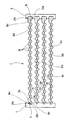
- the crossflow heat exchanger shown in the drawing is designated overall by the reference numeral 2. This has a left hand shown, side flange 4 and a right hand illustrated, side flange 6, wherein the flanges 4 and 6 extend substantially perpendicular to between the flanges 4 and 6 arranged heat exchanger plates 8a to 8h.
- the heat exchanger plates 8a and 8h are each paired in pairs, such as the heat exchanger plates 8a and 8b.
- the heat exchanger plates 8a to 8h have a wave-shaped profile.
- Mutually facing surfaces of paired heat exchanger plates e.g., 8a and 8b
- channels 10 of moist air extending perpendicular to the plane of the drawing.
- channels 12 are formed for the cooling air.
- Four pairs of heat exchanger plates 8a to 8h define a total of three channels 12a to 12c for cooling air.
- the lateral flange 4 has on its the flange. 6 facing side slit-shaped receiving portions 14.
- the flange 6 has on its side facing the flange 4 groove-shaped receiving portions 16.
- the edge portions 18c and 18d of the heat exchanger plates 8a and 8b are added. There, the edge portion 18 c forms with the receiving portion 16 a welded joint 20 c. Accordingly, the edge portion 18d of the heat exchanger plate 8b with the receiving portion 16 forms a welded joint 20d.
- the cross-flow heat exchanger shown in the drawing can be produced without using an adhesive, for example made of cast resin.
- the connections 20a to 20d are made by a welding process.
Landscapes
- Engineering & Computer Science (AREA)
- Mechanical Engineering (AREA)
- Physics & Mathematics (AREA)
- Thermal Sciences (AREA)
- General Engineering & Computer Science (AREA)
- Heat-Exchange Devices With Radiators And Conduit Assemblies (AREA)
- Lining Or Joining Of Plastics Or The Like (AREA)
- Drying Of Solid Materials (AREA)
Description
- Die Erfindung betrifft einen Kreuzstromwärmetauscher für Kondensationswäschetrockner, mit einer Vielzahl von aus thermoplastischem Material bestehenden Wärmetauscherplatten, die zueinander parallel geschichtet sind und Kanäle für Feuchtluft und Kühlluft bilden oder begrenzen, mit mindestens einem aus thermoplastischem Material bestehenden Flansch, an dem die Wärmetauscherplatten festgelegt sind. Die Erfindung betrifft auch ein Verfahren zur Herstellung eines Kreuzstromwärmetauschers für Kondensationswäschetrockner.
- Ein solcher Kreuzstromwärmetauscher ist aus der
EP-A-1 106 729 , derEP-A-0 982 427 und derDE-U-91 05 079 bekannt. Bei solchen Wärmetauschern wird als Prozessluft Kühlluft verwendet, die durch den Wärmetauscher hindurchgeleitet wird. Diese Kühlluft kühlt die warme Feuchtluft, die den Wärmetauscher quer zur Kühlluft durchströmt. Durch die Abkühlung der warmen Feuchtluft kann Feuchtigkeit abgeschieden werden, die sich an den Oberflächen der Wärmetauscherplatten niederschlägt und als Kondensat abfließen kann. Die gattungsbildendeEP-A-1106729 beschreibt den Oberbegriff der Ansprüche 1 und 6. - Bei der
EP-A-0 982 427 sind die Wärmetauscherplatten an einem Flansch gehalten, so dass insgesamt ein etwa würfeloder quaderförmiges Gebilde geschaffen wird. Dabei können die Wärmetauscherplatten einzeln oder paarweise am Flansch festgelegt sein. Die Wärmetauscherplatten können auch miteinander, beispielsweise durch zusätzliche Stege, verbunden sein. - Es ist aus der
EP-A-0 982 427 bekannt, die Wärmetauscherplatten mit Hilfe eines Klebers am Flansch festzulegen. Hierfür wird die Verwendung von Gießharz vorgeschlagen. Dies ist nachteilig, da die für ein Gießharz verwendeten Komponenten zuerst mittels einer Mischanlage und Mischkopf miteinander vor dem Vergießen vermischt werden müssen. Nach einer bestimmten Anzahl von Mischvorgängen müssen die Mischvorrichtung und der Mischkopf gespült werden. Außerdem können diese Komponenten gesundheitsbedenkliche Zyanidverbindungen enthalten. Außerdem ist es schwierig oder sogar unmöglich, die durch Gießharz miteinander gefügten thermoplastischen Bauteile einem Recyclingprozess zuzuführen. Schließlich muss das Gemisch aus Spülflüssigkeit und Gießharzrückständen sachgerecht entsorgt werden. - Hiervon ausgehend liegt der Erfindung die Aufgabe zugrunde, einen Kreuzstromwärmetauscher bereitzustellen, bei dem der Flansch einfach und dennoch für die Festigkeit einer anschließender Verschweißung von Vorteil mit einer Vielzahl von Wärmetauscherplatten gefügt werden kann..
- Diese Aufgabe wird erfindungsgemäß mit einem Kreuzstromwärmetauscher gelöst, der die Merkmale des Anspruchs 1 aufweist.
- Hierdurch können die Wärmetauscherplatten und der Flansch direkt, das heißt ohne Verwendung von Gießharz, miteinander gefügt werden. Die Schweißverbindung lässt sich kostengünstig herstellen und gewährleistet außerdem die zur Vermeidung von Leckverlusten erforderliche Dichtheit zwischen Wärmetauscherplatten und Flansch.
- In Ausführung der Erfindung weist der Flansch Aufnahmeabschnitte für Randabschnitte der Wärmetauscherplatten auf. Hierdurch kann die Relativlage von Wärmetauscherplatten und Flansch definiert werden. Dies ist für eine einfache Handhabung der Wärmetauscherplatten von Vorteil, insbesondere dann, wenn diese folienartig und somit biegeschlaff ausgebildet sind.
- Die Aufnahmeabschnitte können stegförmig, insbesondere konisch, ausgebildet sein, so dass sie problemlos zwischen die Wärmetauscherplatten eingeschoben werden können, bevor die Randabschnitte und die Aufnahmeabschnitte durch eines der beschriebenen Schweißverfahren miteinander gefügt werden.
- Die Aufnahmeabschnitte können auch als Durchbrüche ausgebildet sein, so dass Randabschnitte der Wärmetauscherplatten, die Durchbrüche durchgreifend, in diesen aufgenommen sind. Auch hierdurch kann eine gute Stabilität des Verbunds aus Wärmetauscherplatten und Flansch erreicht werden.
- Die Schweißverbindung kann beispielsweise durch Ultraschallschweißen hergestellt sein. Aufgrund der sehr kurzen Schweißzeiten eignet sich dieses Verfahren besonders für die Großserienherstellung einer erfindungsgemäßen Kreuzstromwärmetauschers.
- Die Verbindung kann auch durch Reibschweißen hergestellt sein. Auch mit diesem Verfahren sind verhältnismäßig kurze Prozesszeiten erreichbar, wobei sich das Reibschweißen insbesondere bei Kreuzstromwärmetauschern mit verhältnismäßig großen Abmessungen eignet.
- Eine weitere Möglichkeit zur Herstellung der Verbindung zwischen Wärmetauscherplatten und Flansch ist das Spiegelschweißverfahren. Bei diesem Verfahren wird ein als Spiegel bezeichneter Heizkörper mit den Wärmetauscherplatten und/oder dem Flansch in Anlage gebracht, so dass die Kontaktflächen schmelzen und nach Entfernen des Spiegels unter Druck miteinander gefügt werden können.
- Auch die Verwendung des Laserschweißverfahrens ist möglich. Durch die hohe Energiedichte des Laserstrahlers sind hohe Arbeitsgeschwindigkeiten möglich. Es ist allerdings darauf zu achten, dass die Energiedichte so dosiert wird, dass die Materialien der Wärmetauscherplatten und des Flansches nicht zersetzt werden.
- Eine weitere Möglichkeit zur Herstellung der Verbindung zwischen Wärmetauscherplatten und Flansch ist die Verwendung des Induktionsschweißens. Für diese Fügetechnik wird das Prinzip der Induktionswärme genutzt. Zwischen den am Flansch festzulegenden Wärmetauscherplatten und dem Flansch wird ein Zusatzmaterial positioniert, das ein magnetisch aktivierbares Pulver enthält. Dabei besteht das Zusatzmaterial hauptsächlich aus einem zum Material der Wärmetauscherplatten und/oder des Flansches identischen Material. Die für den Schweißvorgang erforderliche Wärmeenergie wird durch ein hochfrequentes Magnetfeld erzeugt, das durch Hysterese- und Wirbelstromverluste die Partikel erwärmt und dadurch das Zusatzmaterial auf Schmelztemperatur bringt. Dieses überträgt die Wärme auf die Fügeflächen, die dann unter Druck verbunden werden. Dieses Verfahren eignet sich vor allen Dingen dann, wenn die Fügeflächen der Wärmetauscherplatten beziehungsweise des Flansches schwer zugänglich sind.
- Es ist auch möglich, dass in den Flansch elektrische Widerstandselemente integriert sind. Diese erzeugen bei Beaufschlagung mit elektrischer Spannung Wärme, wodurch die den Wärmetauscherplatten zugewandten Fügeflächen des Flansches und der anliegenden Fügeflächen der Wärmetauscherplatten aufgeschmolzen werden können. Bei Erstarrung der aufgeschmolzenen Materialien wird dann eine Verbindung zwischen den Wärmetauscherplatten und dem Flansch ausgebildet.
- Vorteilhafterweise sind die Wärmetauscherplatten aus Polypropylen gebildet. Polypropylen ist vergleichsweise preiswert und lässt sich beispielsweise durch Thermoformen aus Endlosmaterial zu folienartigen Wärmetauscherplatten weiterverarbeiten. Außerdem verfügt Polypropylen über einen Einsatztemperaturbereich bis 110°, wodurch es gegenüber der warmen Feuchtluft eines Kondensationswäschetrockners ausreichend widerstandsfähig ist.
- Vorteilhafterweise ist auch der Flansch aus Polypropylen gebildet, insbesondere deshalb, weil auch die mechanischen Eigenschaften von Polypropylen ausreichend sind, um eine gute Stabilität des erfindungsgemäßen Kreuzstromwärmetauschers zu gewährleisten.
- In jedem Fall ist es vorteilhaft, wenn die Materialien der Wärmetauscherplatten und des Flansches identisch sind. In diesem Fall lässt sich der Kreuzstromwärmetauscher problemlos schweißen und sortenrein recyceln, so dass die Bauteile des Kreuzstromwärmetauschers geschreddert und einen erneuten Verwendung zugeführt werden können.
- Die Erfindung betrifft auch ein Verfahren zur Herstellung eines Kreuzstromwärmetauschers für Kondensationswärmetrockner, insbesondere eines Kreuzstromwärmetauschers, mit den Merkmalen des Anspruchs 6.
- In Ausgestaltung der Erfindung kann auch ein Schweißzusatzmittel verwendet werden, um eine besonders stabile Verbindung zwischen Wärmetauscherplatten und
- Flansch herstellen zu können.
- Wenn das Schweißzusatzmittel aus dem gleichen Material wie die Wärmetauscherplatten und/oder der Flansch gebildet ist, kann der Kreuzstromwärmetauscher auch bei Verwendung eines Schweißzusatzmittels sortenrein recycelt werden.
- Weitere vorteilhafte Ausgestaltungen und Einzelheiten der Erfindung sind der folgenden Beschreibung zu entnehmen, in der die Erfindung anhand des in der Zeichnung dargestellten Ausführungsbeispiels näher beschrieben und erläutert ist.
- Der in der Zeichnung dargestellte Kreuzstromwärmetauscher ist insgesamt mit dem Bezugszeichen 2 bezeichnet. Dieser weist einen linker Hand dargestellten, seitlichen Flansch 4 sowie einen rechter Hand dargestellten, seitlichen Flansch 6 auf, wobei die Flansche 4 und 6 sich im Wesentlichen senkrecht zu zwischen den Flanschen 4 und 6 angeordneten Wärmetauscherplatten 8a bis 8h erstrecken. Die Wärmetauscherplatten 8a und 8h sind jeweils paarweise zusammengefasst, so zum Beispiel die Wärmetauscherplatten 8a und 8b.
- Die Wärmetauscherplatten 8a bis 8h weisen ein wellenförmiges Profil auf. Einander zugewandte Oberflächen von paarweise zusammengefassten Wärmetauscherplatten (beispielsweise 8a und 8b) bilden sich senkrecht zur Zeichenebene erstreckende Kanäle 10 für Feuchtluft aus. Jeweils zwischen zwei zu Paaren zusammengefassten Wärmetauscherplatten sind Kanäle 12 für die Kühlluft ausgebildet. Vier Paare von Wärmetauscherplatten 8a bis 8h begrenzen insgesamt drei Kanäle 12a bis 12c für Kühlluft.
- Der seitliche Flansch 4 weist auf seiner dem Flansch 6 zugewandten Seite schlitzförmige Aufnahmeabschnitte 14 auf. Der Flansch 6 weist auf seiner dem Flansch 4 zugewandten Seite nutenförmige Aufnahmeabschnitte 16 auf.
- In dem oberen Aufnahmeabschnitt 14 des Flansches 4 sind Randabschnitte 18a und 18b der Wärmetauscherplatten 8a und 8b zur Ausbildung einer Schweißverbindung aufgenommen. Die Verbindungsstellen sind in der Zeichnung mit 20a und 20b markiert.
- Im oberen Aufnahmeabschnitt 16 des Flansches 6 sind die Randabschnitte 18c und 18d der Wärmetauscherplatten 8a und 8b aufgenommen. Dort bildet der Randabschnitt 18c mit dem Aufnahmeabschnitt 16 eine Schweißverbindung 20c aus. Entsprechend bildet der Randabschnitt 18d der Wärmetauscherplatte 8b mit dem Aufnahmeabschnitt 16 eine Schweißverbindung 20d aus.
- Der in der Zeichnung dargestellte Kreuzstromwärmetauscher kann ohne Verwendung eines Klebers, beispielsweise aus Gießharz, hergestellt werden. Die Verbindungen 20a bis 20d sind durch ein Schweißverfahren hergestellt.
Claims (8)
- Kreuzstromwärmetauscher (2) für Kondensationswäschetrockner, mit einer Vielzahl von aus thermoplastischem Material bestehenden, folienartiger, biegeschlaffer Wärmetauscherplatten (8), die zueinander parallel geschichtet sind und Kanäle (10, 12) für Feuchtluft und einem Kühlfluid, insbesondere Kühlluft bilden oder begrenzen, mit mindestens einem aus thermoplastischem Material bestehenden Flansch (4, 6), an dem die Wärmetauscherplatten (8) durch eine Schweißverbindung festgelegt sind, dadurch gekennzeichnet, dass der Flansch (4, 6) Aufnahmeabschnitte (14, 16) für jeweils zwei paarweise zusammengefasster Randabschnitte (18) zweier Wärmetauscherplatten (8) aufweist und die Randabschnitte (18) der Wärmetauscherplatten (8) und die Aufnahmeabschnitte (14, 16) des Flansches (4, 6) durch die Schweißverbindung (20) miteinander verbunden sind, wobei die Aufnahmeabschnitte (14, 16) als abragende, insbesondere konische Stege oder als Durchbrüche ausgebildet sind.
- Kreuzstromwärmetauscher nach Anspruch 1, dadurch gekennzeichnet, dass die Verbindung (20) durch Ultraschallschweißen, Reibschweißen, Heizelementschweißen, Laserschweißen oder durch Induktionsschweißen hergestellt ist.
- Kreuzstromwärmetauscher nach Anspruch 1, dadurch gekennzeichnet, dass in den Flansch (4, 6) mit Spannung beaufschlagbare elektrische Widerstandselemente integriert sind.
- Kreuzstromwärmetauscher nach einem der vorhergehenden Ansprüche, dadurch gekennzeichnet, dass die Wärmetauscherplatten (8) und/oder der Flansch (4, 6) aus Polypropylen ausgebildet ist/sind.
- Kreuzstromwärmetauscher nach einem der vorhergehenden Ansprüche, dadurch gekennzeichnet, dass die Materialien der Wärmetauscherplatten (8) und des Flansches (4, 6) identisch sind.
- Verfahren zur Herstellung eines Kreuzstromwärmetauschers für Kondensationswärmetrockner, insbesondere eines Kreuzstromwärmetauschers (2) nach einem der vorhergehenden Ansprüche, mit einer Vielzahl von aus thermoplastischem Material bestehenden, folienartiger, biegeschlaffer Wärmetauscherplatten (8), die zueinander parallel geschichtet sind und Kanäle (10, 12) für Feuchtluft und einem Kühlfluid, insbesondere Kühlluft, bilden oder begrenzen, mit mindestens einem aus thermoplastischem Material bestehenden Flansch (4, 6), an dem die Wärmetauscherplatten (8) angeschweißt sind, dadurch gekennzeichnet, dass jeweils zwei paarweise zusammengefasste Randabschnitte (18) zweier Wärmetauscherplatten (8) und Aufnahmeabschnitte (14, 16) des Flansches (4, 6), welche als abragende, insbesondere konische Stege oder als Durchbrüche ausgebildet sind, zur Aufnahme der paarweise zusammengefassten Randabschnitte (18) der Wärmetauscherplatten (8) ineinander gesteckt und durch die Schweißverbindung (20) miteinander verbunden werden.
- Verfahren nach Anspruch 6, dadurch gekennzeichnet, dass ein Schweißzusatzmittel verwendet wird.
- Verfahren nach Anspruch 7, dadurch gekennzeichnet, dass als Schweißzusatzmittel das gleiche Material wie die Wärmetauscherplatten (8) und/oder der Flansch (4, 6) verwendet wird.
Applications Claiming Priority (2)
| Application Number | Priority Date | Filing Date | Title |
|---|---|---|---|
| DE10356417 | 2003-11-27 | ||
| DE10356417A DE10356417A1 (de) | 2003-11-27 | 2003-11-27 | Kreuzstromwärmetauscher für Kondensationswäschetrockner |
Publications (3)
| Publication Number | Publication Date |
|---|---|
| EP1550835A2 EP1550835A2 (de) | 2005-07-06 |
| EP1550835A3 EP1550835A3 (de) | 2006-10-04 |
| EP1550835B1 true EP1550835B1 (de) | 2011-10-05 |
Family
ID=34559752
Family Applications (1)
| Application Number | Title | Priority Date | Filing Date |
|---|---|---|---|
| EP04400054A Expired - Lifetime EP1550835B1 (de) | 2003-11-27 | 2004-10-21 | Kreuzstromwärmetauscher für Kondensationswäschetrockner |
Country Status (2)
| Country | Link |
|---|---|
| EP (1) | EP1550835B1 (de) |
| DE (1) | DE10356417A1 (de) |
Cited By (1)
| Publication number | Priority date | Publication date | Assignee | Title |
|---|---|---|---|---|
| WO2025247963A1 (en) * | 2024-05-30 | 2025-12-04 | Zehnder Group International Ag | Method for producing a heat exchanger |
Families Citing this family (3)
| Publication number | Priority date | Publication date | Assignee | Title |
|---|---|---|---|---|
| DE202007007169U1 (de) | 2007-05-16 | 2008-09-25 | Akg-Thermotechnik Gmbh & Co. Kg | Wärmeaustauscher für gasförmige Medien |
| FR3041422B1 (fr) * | 2015-09-17 | 2017-12-01 | Novares France | Dispositif pour moteur comprenant un carter d’huile et un echangeur thermique |
| DE102020211603A1 (de) | 2020-09-16 | 2022-03-17 | Fränkische Industrial Pipes GmbH & Co. KG | Vorrichtung zum temperieren eines bauteils und herstellungsverfahren der vorrichtung |
Family Cites Families (9)
| Publication number | Priority date | Publication date | Assignee | Title |
|---|---|---|---|---|
| FR2088166B1 (de) * | 1970-05-25 | 1974-05-03 | Chausson Usines Sa | |
| DE2165267A1 (de) * | 1971-12-29 | 1973-07-12 | Krupp Gmbh | Waermetauscher |
| FR2339830A1 (fr) * | 1976-01-29 | 1977-08-26 | Alsthom Cgee | Procede de fabrication d'une plaque d'echange de chaleur |
| JPS5822896A (ja) * | 1981-08-03 | 1983-02-10 | Hitachi Ltd | プラスチツク熱交換器 |
| DE9105079U1 (de) * | 1991-04-25 | 1991-12-05 | Licentia Patent-Verwaltungs-Gmbh, 6000 Frankfurt | Luftgekühlter Wärmetauscher für einen Wäschetrockner |
| EP0982427B1 (de) * | 1998-08-25 | 2003-03-05 | Joma-Polytec Kunststofftechnik GmbH | Kreuzstrom-Wärmetauscher für Kondensationswäschetrockner |
| FR2785375B1 (fr) * | 1998-10-28 | 2001-01-12 | Valeo Thermique Moteur Sa | Echangeur de chaleur a faisceau de tubes et collecteurs en materiau thermoplastique |
| EP1106729B1 (de) * | 1999-12-02 | 2003-07-23 | Joma-Polytec Kunststofftechnik GmbH | Kreuzstrom-Wärmetauscher für Kondensationswäschetrockner |
| JP2004125270A (ja) * | 2002-10-02 | 2004-04-22 | Denso Corp | 熱交換器およびその製造方法 |
-
2003
- 2003-11-27 DE DE10356417A patent/DE10356417A1/de not_active Withdrawn
-
2004
- 2004-10-21 EP EP04400054A patent/EP1550835B1/de not_active Expired - Lifetime
Cited By (1)
| Publication number | Priority date | Publication date | Assignee | Title |
|---|---|---|---|---|
| WO2025247963A1 (en) * | 2024-05-30 | 2025-12-04 | Zehnder Group International Ag | Method for producing a heat exchanger |
Also Published As
| Publication number | Publication date |
|---|---|
| EP1550835A2 (de) | 2005-07-06 |
| DE10356417A1 (de) | 2005-06-30 |
| EP1550835A3 (de) | 2006-10-04 |
Similar Documents
| Publication | Publication Date | Title |
|---|---|---|
| DE60222566T2 (de) | Verschweissungstechniken für ein polymer oder polymerverbundbestandteile | |
| DE68917184T2 (de) | Verfahren zur Herstellung eines geschweissten, wabenförmigen Kernes. | |
| EP0398459B1 (de) | Filtereinsatz | |
| DE3886579T2 (de) | Mittels Polymeren hergestellter Wärmetauscher. | |
| DE2352550C2 (de) | Verbundbindemittel zum Verbinden zweier verbundunverträglicher Kunststoffkörper | |
| DE69317812T2 (de) | Heizelement für eine Schlauch-Ankuppel-Anordnung | |
| DE102020205385A1 (de) | Plattenartiger Fluidbehälter | |
| DE2522106B2 (de) | Vorrichtung zum kontinuierlichen Mischen fließfähiger Stoffe und Verfahren zum Herstellen eines Mischeinsatzes | |
| EP3718164A1 (de) | Hybridbauteil mit temperierraum | |
| DE112012006261T5 (de) | Kabelstrang, Verfahren zur Herstellung von Kabelstrang, und Schutzelement | |
| DE3177283T2 (de) | Warmschrumpfbare gegenstaende. | |
| DE3212295A1 (de) | Verfahren zum verbinden zweier flaechen von platten | |
| DE2844695A1 (de) | Verfahren zur herstellung einer elektrochemischen zelle oder batterie | |
| DE102008044087A1 (de) | Verfahren zum Herstellen von Überlappungsstoßschweißverbindungen und Überlappungsstoßschweißverbindung | |
| EP1550835A2 (de) | Kreuzstromwärmetauscher für Kondensationswäschetrockner | |
| DE69307126T2 (de) | Verfahren zur herstellung von wärmetauschern | |
| DE68908128T2 (de) | Verfahren zum Formen von Werkstücken aus faserverstärkten thermoplastischen Werkstoffen. | |
| DE102012012749B4 (de) | Verfahren zur Herstellung einer Bipolarplatte einer Brennstoffzelle und Bipolarplatte | |
| DE202008017839U1 (de) | Solarflachkollektor und dessen Herstellung | |
| DE102009002157B4 (de) | Verfahren und Vorrichtung zur Ausrichtung nichtmagnetischer elektrisch leitfähiger Fasern | |
| DE102015109483A1 (de) | Faserverbundbauteil | |
| WO2014177508A1 (de) | Verfahren zum herstellen eines dialysefilters und eine vorrichtung hierfür | |
| DE102018129345A1 (de) | Verfahren zum Herstellen eines Filterelements und Filterelement | |
| WO2010012808A9 (de) | Verfahren zur herstellung eines fahrzeug-verkleidungsteils sowie verkleidungsteil | |
| DE69110949T2 (de) | Verfahren zur Herstellung einer Kunststoffplatte. |
Legal Events
| Date | Code | Title | Description |
|---|---|---|---|
| PUAI | Public reference made under article 153(3) epc to a published international application that has entered the european phase |
Free format text: ORIGINAL CODE: 0009012 |
|
| AK | Designated contracting states |
Kind code of ref document: A2 Designated state(s): AT BE BG CH CY CZ DE DK EE ES FI FR GB GR HU IE IT LI LU MC NL PL PT RO SE SI SK TR |
|
| AX | Request for extension of the european patent |
Extension state: AL HR LT LV MK |
|
| PUAL | Search report despatched |
Free format text: ORIGINAL CODE: 0009013 |
|
| AK | Designated contracting states |
Kind code of ref document: A3 Designated state(s): AT BE BG CH CY CZ DE DK EE ES FI FR GB GR HU IE IT LI LU MC NL PL PT RO SE SI SK TR |
|
| AX | Request for extension of the european patent |
Extension state: AL HR LT LV MK |
|
| 17P | Request for examination filed |
Effective date: 20061110 |
|
| AKX | Designation fees paid |
Designated state(s): DE |
|
| 17Q | First examination report despatched |
Effective date: 20081112 |
|
| RAP1 | Party data changed (applicant data changed or rights of an application transferred) |
Owner name: JOMA-POLYTEC GMBH |
|
| GRAP | Despatch of communication of intention to grant a patent |
Free format text: ORIGINAL CODE: EPIDOSNIGR1 |
|
| GRAS | Grant fee paid |
Free format text: ORIGINAL CODE: EPIDOSNIGR3 |
|
| GRAA | (expected) grant |
Free format text: ORIGINAL CODE: 0009210 |
|
| RTI1 | Title (correction) |
Free format text: CROSS FLOW HEAT EXCHANGER FOR LAUNDRY DRYER WITH CONDENSER |
|
| AK | Designated contracting states |
Kind code of ref document: B1 Designated state(s): DE |
|
| REG | Reference to a national code |
Ref country code: DE Ref legal event code: R096 Ref document number: 502004012930 Country of ref document: DE Effective date: 20120105 |
|
| PLBE | No opposition filed within time limit |
Free format text: ORIGINAL CODE: 0009261 |
|
| STAA | Information on the status of an ep patent application or granted ep patent |
Free format text: STATUS: NO OPPOSITION FILED WITHIN TIME LIMIT |
|
| 26N | No opposition filed |
Effective date: 20120706 |
|
| REG | Reference to a national code |
Ref country code: DE Ref legal event code: R097 Ref document number: 502004012930 Country of ref document: DE Effective date: 20120706 |
|
| PGFP | Annual fee paid to national office [announced via postgrant information from national office to epo] |
Ref country code: DE Payment date: 20151218 Year of fee payment: 12 |
|
| REG | Reference to a national code |
Ref country code: DE Ref legal event code: R119 Ref document number: 502004012930 Country of ref document: DE |
|
| PG25 | Lapsed in a contracting state [announced via postgrant information from national office to epo] |
Ref country code: DE Free format text: LAPSE BECAUSE OF NON-PAYMENT OF DUE FEES Effective date: 20170503 |