EP1550817B1 - Vorrichtung zur Stabilisierung der Verstärkung einer selbstversärkenden Scheibenbremse - Google Patents
Vorrichtung zur Stabilisierung der Verstärkung einer selbstversärkenden Scheibenbremse Download PDFInfo
- Publication number
- EP1550817B1 EP1550817B1 EP04257965A EP04257965A EP1550817B1 EP 1550817 B1 EP1550817 B1 EP 1550817B1 EP 04257965 A EP04257965 A EP 04257965A EP 04257965 A EP04257965 A EP 04257965A EP 1550817 B1 EP1550817 B1 EP 1550817B1
- Authority
- EP
- European Patent Office
- Prior art keywords
- support
- angle
- recited
- brake pad
- assembly
- Prior art date
- Legal status (The legal status is an assumption and is not a legal conclusion. Google has not performed a legal analysis and makes no representation as to the accuracy of the status listed.)
- Expired - Lifetime
Links
- 230000007246 mechanism Effects 0.000 title description 2
- 230000000087 stabilizing effect Effects 0.000 title description 2
- 230000003247 decreasing effect Effects 0.000 claims description 2
- 230000008901 benefit Effects 0.000 description 4
- 239000002783 friction material Substances 0.000 description 4
- 238000010586 diagram Methods 0.000 description 2
- 238000012986 modification Methods 0.000 description 2
- 230000004048 modification Effects 0.000 description 2
- 230000000712 assembly Effects 0.000 description 1
- 238000000429 assembly Methods 0.000 description 1
- 239000000463 material Substances 0.000 description 1
- 230000006641 stabilisation Effects 0.000 description 1
- 238000011105 stabilization Methods 0.000 description 1
Images

Classifications
-
- F—MECHANICAL ENGINEERING; LIGHTING; HEATING; WEAPONS; BLASTING
- F16—ENGINEERING ELEMENTS AND UNITS; GENERAL MEASURES FOR PRODUCING AND MAINTAINING EFFECTIVE FUNCTIONING OF MACHINES OR INSTALLATIONS; THERMAL INSULATION IN GENERAL
- F16D—COUPLINGS FOR TRANSMITTING ROTATION; CLUTCHES; BRAKES
- F16D55/00—Brakes with substantially-radial braking surfaces pressed together in axial direction, e.g. disc brakes
- F16D55/24—Brakes with substantially-radial braking surfaces pressed together in axial direction, e.g. disc brakes with a plurality of axially-movable discs, lamellae, or pads, pressed from one side towards an axially-located member
- F16D55/46—Brakes with substantially-radial braking surfaces pressed together in axial direction, e.g. disc brakes with a plurality of axially-movable discs, lamellae, or pads, pressed from one side towards an axially-located member with self-tightening action
- F16D55/48—Brakes with substantially-radial braking surfaces pressed together in axial direction, e.g. disc brakes with a plurality of axially-movable discs, lamellae, or pads, pressed from one side towards an axially-located member with self-tightening action with discs or pads having a small free angular travel relative to their support, which produces the self-tightening action
-
- F—MECHANICAL ENGINEERING; LIGHTING; HEATING; WEAPONS; BLASTING
- F16—ENGINEERING ELEMENTS AND UNITS; GENERAL MEASURES FOR PRODUCING AND MAINTAINING EFFECTIVE FUNCTIONING OF MACHINES OR INSTALLATIONS; THERMAL INSULATION IN GENERAL
- F16D—COUPLINGS FOR TRANSMITTING ROTATION; CLUTCHES; BRAKES
- F16D49/00—Brakes with a braking member co-operating with the periphery of a drum, wheel-rim, or the like
- F16D49/20—Self-tightening brakes
-
- F—MECHANICAL ENGINEERING; LIGHTING; HEATING; WEAPONS; BLASTING
- F16—ENGINEERING ELEMENTS AND UNITS; GENERAL MEASURES FOR PRODUCING AND MAINTAINING EFFECTIVE FUNCTIONING OF MACHINES OR INSTALLATIONS; THERMAL INSULATION IN GENERAL
- F16D—COUPLINGS FOR TRANSMITTING ROTATION; CLUTCHES; BRAKES
- F16D65/00—Parts or details
- F16D65/02—Braking members; Mounting thereof
- F16D65/04—Bands, shoes or pads; Pivots or supporting members therefor
- F16D65/092—Bands, shoes or pads; Pivots or supporting members therefor for axially-engaging brakes, e.g. disc brakes
- F16D65/095—Pivots or supporting members therefor
- F16D65/097—Resilient means interposed between pads and supporting members or other brake parts
- F16D65/0971—Resilient means interposed between pads and supporting members or other brake parts transmitting brake actuation force, e.g. elements interposed between brake piston and pad
-
- F—MECHANICAL ENGINEERING; LIGHTING; HEATING; WEAPONS; BLASTING
- F16—ENGINEERING ELEMENTS AND UNITS; GENERAL MEASURES FOR PRODUCING AND MAINTAINING EFFECTIVE FUNCTIONING OF MACHINES OR INSTALLATIONS; THERMAL INSULATION IN GENERAL
- F16D—COUPLINGS FOR TRANSMITTING ROTATION; CLUTCHES; BRAKES
- F16D65/00—Parts or details
- F16D65/02—Braking members; Mounting thereof
- F16D65/04—Bands, shoes or pads; Pivots or supporting members therefor
- F16D65/092—Bands, shoes or pads; Pivots or supporting members therefor for axially-engaging brakes, e.g. disc brakes
- F16D65/095—Pivots or supporting members therefor
- F16D65/097—Resilient means interposed between pads and supporting members or other brake parts
- F16D65/0972—Resilient means interposed between pads and supporting members or other brake parts transmitting brake reaction force, e.g. elements interposed between torque support plate and pad
-
- F—MECHANICAL ENGINEERING; LIGHTING; HEATING; WEAPONS; BLASTING
- F16—ENGINEERING ELEMENTS AND UNITS; GENERAL MEASURES FOR PRODUCING AND MAINTAINING EFFECTIVE FUNCTIONING OF MACHINES OR INSTALLATIONS; THERMAL INSULATION IN GENERAL
- F16D—COUPLINGS FOR TRANSMITTING ROTATION; CLUTCHES; BRAKES
- F16D65/00—Parts or details
- F16D65/14—Actuating mechanisms for brakes; Means for initiating operation at a predetermined position
-
- F—MECHANICAL ENGINEERING; LIGHTING; HEATING; WEAPONS; BLASTING
- F16—ENGINEERING ELEMENTS AND UNITS; GENERAL MEASURES FOR PRODUCING AND MAINTAINING EFFECTIVE FUNCTIONING OF MACHINES OR INSTALLATIONS; THERMAL INSULATION IN GENERAL
- F16D—COUPLINGS FOR TRANSMITTING ROTATION; CLUTCHES; BRAKES
- F16D65/00—Parts or details
- F16D65/14—Actuating mechanisms for brakes; Means for initiating operation at a predetermined position
- F16D65/16—Actuating mechanisms for brakes; Means for initiating operation at a predetermined position arranged in or on the brake
- F16D65/18—Actuating mechanisms for brakes; Means for initiating operation at a predetermined position arranged in or on the brake adapted for drawing members together, e.g. for disc brakes
-
- F—MECHANICAL ENGINEERING; LIGHTING; HEATING; WEAPONS; BLASTING
- F16—ENGINEERING ELEMENTS AND UNITS; GENERAL MEASURES FOR PRODUCING AND MAINTAINING EFFECTIVE FUNCTIONING OF MACHINES OR INSTALLATIONS; THERMAL INSULATION IN GENERAL
- F16D—COUPLINGS FOR TRANSMITTING ROTATION; CLUTCHES; BRAKES
- F16D2127/00—Auxiliary mechanisms
- F16D2127/08—Self-amplifying or de-amplifying mechanisms
- F16D2127/10—Self-amplifying or de-amplifying mechanisms having wedging elements
Definitions
- This invention generally relates to a disk brake assembly and specifically to a self-energized disk brake assembly including features for stabilizing braking force gain.
- the mechanical force is typically provided by a hydraulic piston actuated to force brake pads against a rotor.
- the piston is typically movable within a caliper housing.
- the caliper housing is either of a fixed or floating configuration.
- a fixed caliper housing remains fixed relative to the rotor as the brake pads move into contact with the rotor.
- a fixed caliper includes two pistons for moving the brake pads into engagement with the rotor.
- a floating caliper uses a single piston that moves one of the brake pads into contact with the rotor, and floats to pull the second pad into contact on an opposite side of the rotor.
- a Self-energizing brake creates additional braking forces above any applied force to increase braking forces on the rotating brake member.
- Self-energizing brakes are known in the art, and have several problems that have so far prevented wide spread use in motor vehicles.
- the multiplication of braking force is generated by a specific configuration of brake pad or shoe and a frictional force caused during engagement with the rotating brake member. An applied force causes engagement between the rotating brake member and the brake pad. Rotation of the rotating brake member pulls the brake pad or shoe into the rotor, multiplying the overall braking force.
- Document DE 11 69 218 B discloses a self-energizing brake assembly according to the preamble of claim 1.
- the present invention is a self-energizing brake assembly including gain stabilization features controlling braking force gains obtained through self-energization, as defined in claim 1.
- a brake assembly designed according to this invention includes a brake pad movable on a support.
- the support is pivotally mounted to provide adjustment of an angle defined between the support and a centerline of a rotor.
- a force applied to the brake pad causes engagement between the rotor and the brake pad.
- a frictional force includes a friction coefficient between the rotor and the friction material and a normal force. The frictional force pulls the brake pad along the support to increase the magnitude of braking force beyond the force applied by the actuator.
- the increase in braking force is related to the angle of the support relative to the rotating brake member.
- the normal force varies in relation to changes in the angle. Therefore, adjusting the angle of the support controls the magnitude of braking force applied to the rotating brake member.
- the present invention provides a brake assembly that controls gain from self-energization features and multiplies braking forces beyond the capability of the brake actuator.
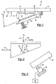
- a brake assembly 10 includes a brake pad 14 movable on a support 22.
- the support 22 is pivotally mounted to provide adjustment of an angle 30 defined between the support 22 and a plane of the braking surface 40 of a rotor 12.
- a force indicated by arrow 28 applied to the brake pad 14 moves the brake pad 14 into engagement with the rotor 12.
- Frictional force 38 pulls the brake pad 14 along the support 22 toward pivot 24 causing a decrease in available space between the brake pad 14 and rotor 12.
- the decrease in space causes an increase in the magnitude of braking force.
- the increase in braking force is beyond the applied force 28 that initially causes contact between the brake pad 14 and rotor 12. Adjusting the angle 30 controls the magnitude of the increase in braking force.
- the brake pad 14 includes a wedge 16 slidable along the support 22.
- the wedge 16 moves along the support on rollers 26.
- rollers 26 are shown, other devices and mechanisms for moving the wedge 16 relative to the support 22, such as a polished and lubricated surface, are within the contemplation of this invention.
- a friction element 18 is pivotally attached to the wedge 16 for rotation about a pivot 20. The friction element 18 pivots about the pivot 20 to maintain contact with the rotor 12 through changes in the angle 30 of the support 22.
- the support 22 rotates about a pivotal connection 24 and facilitates changes in the angle 30.
- a spring 32 biases the support 22 toward the rotor 12. Friction force 38 between the brake pad 14 and the rotor 12 drives the brake pad 14 along the support 22 and into the rotor 12. Movement of the brake pad 14 up the support 22 increases braking force against the rotor 12.
- a counter force 46 generated by movement of the brake pad 14 along the support 22 drives the support 22 away from the rotor 12 against the biasing force exerted by the spring 32.
- the biasing force exerted by the spring 32 is balanced against the counter force 46 such that the angle 30 is continuously varied to control and maintain a desired amount and increase in braking force on the rotor 12.
- a free body diagram illustrates forces acting on the brake pad 14 as the brake pad 14 contacts the rotor 12.
- the applied force 28 moves the wedge 16 up the support 22 and into engagement with the rotor 12.
- the friction force 38 consists of the product of a friction coefficient between the rotor 12 and the friction material 18 and a normal force 42.
- the friction force 38 pulls the brake pad 14 up the support 22.
- the normal force 42 increases, and the braking force against the rotor 12 increases.
- the normal force 42 increases, the wedge 16 is drawn further up the support 22, causing a further self-energized increase in braking force.
- the normal force 42 is a component of a force 44 acting perpendicular to the support 22.
- the normal force 42 varies in relation to changes in the angle 30. Variation in the angle 30 controls the magnitude of normal force 42 exerted between the rotor 12 and the brake pad 14 to control the amount of gain in braking force and control self-energization.
- another embodiment of the brake assembly 10 includes a linear actuator 34 instead of a biasing spring 32.
- the actuator 34 drives an actuation arm 36 to vary the angle 30.
- the use of an actuator 34 instead of the biasing spring 32 provides for situational control over adjustment of the angle 30.
- the actuator 34 allows for the adjustment of the angle 30 in a different manner depending on application specific conditions. For example, it may be desirable to brake a vehicle differently when heavily loaded, or when proceeding down a steep incline.
- the actuator 34 is controlled by a controller 35 to move the actuator arm 36, vary the angle 30, and control the magnitude of braking force in response to current conditions.
- the controller 35 is as known, and a worker skilled in the art with the benefit of the teachings contained herein would understand how to program the controller 35 to vary the angle 30 and control braking forces in response to various vehicle conditions.
- another brake assembly 50 includes a wedge shaped brake pad 58 movable along a support 54.
- the support 54 includes a ramped surface 59 on which the brake pad 58 slides.
- the brake pad 58 includes friction material 60 forming the surface engaging the rotor 52.
- the support 54 is pivotally supported for rotation about a pivot 82.
- An actuator 66 drives the support 54 upward decreasing an angle 78. The decrease in the angle 78 moves the brake pad 58 into engagement with the rotor 52.
- Friction force 38' causes movement of the brake pad 58 up the sloping surface 59 defined by the support 54. Upward movement increases the braking force against the rotor 52 beyond the force 80 applied by the drive actuator 66.
- a release spring 86 biases the brake pad 58 in a direction counter to the direction of rotation 64 of the rotor 52.
- the release spring 86 biases the brake pad 58 down the sloping surface 59 of the support 54.
- the magnitude of braking force increases beyond the applied force 80 by the self-energization gain obtained from the friction force 38' pushing the brake pad 58 up the sloping surface 59.
- the magnitude of braking force gain increases proportionally relative to movement of the brake pad 58 up the support 54.
- the angle 78 between the sloping surface 59 and a centerline 62 of the rotor 52 is varied to control the gain in braking force from self-energization.
- the drive actuator 66 moves a drive link 70 upward to initiate contact between the brake pad 58 and the rotor 52.
- the force 80 exerted by the drive actuator 66 may be only a fraction of the actual force required to brake the rotor 52.
- the remainder of the braking force required to control and brake the rotor 52 is provided by self-energization caused by frictional forces pulling the brake pad 58 up the sloping surface 59 and toward the rotor 52.
- the drive actuator 66 adjusts the angle 78 to provide a desired magnitude of force gain above the applied force 80.
- a controller 65 controls the drive actuator 66 in order to provide the desired magnitude of braking force.
- the controller 65 also directs actuation of a lock actuator 68.
- the lock actuator 68 includes a lock link 72.
- the lock link 72 and drive link 70 include teeth 74 having ramped surfaces 76 that translates linear movement of the lock link 72 in the direction 71 into transverse movement 73 of the drive link 70.
- the lock actuator 68 and lock link 72 prevent movement of the drive link 70 caused by forces produced between the rotor 52 and the support 54. Further, the lock link 72 provides an increase in release force required to unlock the brake pad 58 from the rotor 52.
- a worker skilled in the art with the benefit of the teachings disclosed herein would understand how to program a commercially available controller to control actuation of the drive and lock actuators 66, 68 to adjust the angle 78 and control the magnitude of self-energized gain in braking force.
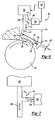
- another brake assembly 90 includes a brake pad 94 movable along a sloped surface 115 of a pivotal support 116.
- the brake pad 94 includes friction material 96 that contacts an outer periphery of a rotor 92.
- Contact between the rotor 92 and the brake pad 94 drives the brake pad 94 along the sloped surface 115 and further toward the rotor 92.
- Frictional force 124 drives the brake pad 94 along the sloped surface 115 to shorten the distance between the brake pad 94 and the rotor 92.
- the shortened distance results in a gain in braking force above that of an applied force122.
- the applied force 122 initiates contact between the brake pad 94 and the rotor 92, and the friction force 124 drives the brake pad 94 along the sloped surface 115 creating a self-energized increase in braking force.
- the support 116 pivots about pivot 114 in response to the applied force 112 exerted by the drive actuator 102.
- the drive actuator 102 is pivotally attached to the support 116 by a pivot 118.
- the drive actuator 102 drives a drive link 106 to adjust an angle 120 between the sloped surface 115 and a line tangent to rotation of the rotor 92.
- the drive actuator 102 and release actuator are controlled by a controller 103.
- the controller 103 may be a portion of the vehicle electronic control module or a separate dedicated controller for the brake assembly 90. A worker skilled in the art, with the benefit of this application would understand how to program a commercially available controller to adjust the angle 120.
- the release actuator 104 moves a release link 108 linearly and perpendicular to movement of the drive link 106.
- Teeth 110 form an interface between the drive link 106 and the release link 108.
- the teeth 110 include ramped surfaces 112 to convert linear movement of the release link into perpendicular movement of the drive link 106.
- Actuation of the release actuator 104 toward the drive link 106 causes movement of the drive link 106 away from the support 116 to increase the angle 120.
- Increasing the angle 120 reduces the self-energization gain obtained from movement of the brake pad 94 along the sloped surface 115.
- Continuous adjustment of the angle 120 controls the magnitude of braking force increase from self-energization.
- Self-energization allows the use of smaller actuators with less power because most of the braking force is produced by self-energization of the brake pad 94.
Landscapes
- Engineering & Computer Science (AREA)
- General Engineering & Computer Science (AREA)
- Mechanical Engineering (AREA)
- Braking Arrangements (AREA)
Claims (16)
- Selbstverstärkende Bremsenanordnung, die Folgendes umfasst:einen Träger (22), der in einem Winkel zu einem drehbaren Bremsglied (12) schwenkbar angebracht ist, wobei der Winkel zwischen dem Träger und einer Ebene der Bremsfläche des drehbaren Bremsglieds (12) definiert ist; undeinen Bremsbelag (14), der entlang dem Träger (22) zwischen einer eingerückten und einer ausgerückten Stellung beweglich ist, wobei das drehbare Bremsglied (12) eine Bremskraft zwischen dem Bremsbelag (14) und dem drehbaren Bremsglied (12) erzeugen soll, dadurch gekennzeichnet, dass der Träger schwenkbar ist, um den Winkel zur Steuerung einer Verstärkungsgröße der Bremskraft einzustellen, und der Träger ein einstellbares Glied (32) enthält, das den Träger (22) zu dem drehbaren Bremsglied (12) vorspannt.
- Anordnung (10) nach Anspruch 1, wobei der Bremsbelag (14) einen Keil (16) und ein Reibelement (18) umfasst, das schwenkbar an dem Keil angebracht ist.
- Anordnung nach Anspruch 2, wobei der Eingriff zwischen dem Reibelement und dem drehbaren Bremsglied (12) den Bremsbelag (14) entlang dem Träger und zu dem drehbaren Bremsglied (12) schiebt, um die Bremskraft zu vergrößern.
- Anordnung nach einem der vorhergehenden Ansprüche, wobei der Träger an einem ersten Ende schwenkbar ist und das einstellbare Glied (32) auf den Träger (22) an einem zweiten Ende eine Kraft ausübt.
- Anordnung nach einem der vorhergehenden Ansprüche, wobei das einstellbare Glied ein elastisches Glied (32) oder ein Linearstellglied (34, 66, 102) umfasst.
- Anordnung nach einem der vorhergehenden Ansprüche, die eine Auslösefeder (86) umfasst, um den Bremsbelag (58) in eine der Drehung des drehbaren Bremsglieds (52) entgegengesetzte Richtung vorzuspannen.
- Anordnung nach einem der Ansprüche 1 bis 4, wobei das einstellbare Glied ein Antriebsstellglied (66) umfasst, um durch Verkleinern des Winkels zwischen dem drehbaren Bremsglied (52) und dem Träger (54) an den Bremsbelag (58) eine Kraft anzulegen.
- Anordnung nach Anspruch 7, die ein Auslösestellglied (68) umfasst, um den Träger (54) zur Einstellung des Winkels zwischen dem drehbaren Bremsglied (52) und dem Träger (54) zu bewegen.
- Anordnung nach Anspruch 8, wobei das Antriebsstellglied (66) eine Antriebsverbindung (70) enthält, die schwenkbar an dem Träger befestigt ist, und das Auslösestellglied (68) eine Auslöseverbindung (72) enthält, wobei die Auslöseverbindung (72) und die Antriebsverbindung (70) eine solche Verbindung aufweisen, dass durch Betätigung der Auslöseverbindung (72) die Antriebsverbindung zur Vergrößerung des Winkels bewegt wird.
- Anordnung nach Anspruch 9, wobei die Verbindung entsprechende Rampenflächen an der Antriebsverbindung (70) und der Auslöseverbindung (72) umfasst, um die Antriebsverbindung (70) quer zur Bewegung der Auslöseverbindung (72) zu bewegen.
- Anordnung nach einem der vorhergehenden Ansprüche, wobei der Bremsbelag (18) einen Außenumfang des drehbaren Glieds (12) berührt.
- Verfahren zur Steuerung der Bremskraftverstärkung, die durch eine selbstverstärkende Bremsenanordnung nach einem der Ansprüche 1 bis 11 erzeugt wird, mit den folgenden Schritten:a) Stützen eines Bremsbelags (14) bezüglich eines drehbaren Bremsglieds (12) auf einem Träger (22), der in einem Winkel (30) zu dem drehbaren Bremsglied (12) schwenkbar angebracht ist, wobei der Winkel zwischen dem Träger (22) und einer Ebene der Bremsfläche des drehbaren Bremsglieds (12) definiert ist, wobei der Träger (22) schwenkbar ist, um den Winkel (30) zur Steuerung einer Verstärkungsgröße der Bremskraft einzustellen, und wobei der Träger (22) ein einstellbares Glied (32) enthält, das den Träger zu dem drehbaren Bremsglied (12) vorspannt; undb) Ändern eines Abstands des Trägers (22) bezüglich des drehbaren Bremsglieds (12) durch Einstellen des Winkels (30) als Reaktion auf eine vorbestimmte Verstärkung der Bremskraft.
- Verfahren nach Anspruch 12, wobei Schritt (a) verschiebbares Stützen des Bremsbelags (14) in einem Winkel zu dem drehbaren Bremsglied (12) und Ändern des Winkels (30) im Verhältnis der Bremskraft umfasst.
- Verfahren nach Anspruch 12 oder 13, das Vorspannen des Bremsbelags (14) in einer Richtung entgegen der Drehung des drehbaren Bremsglieds (12) umfasst.
- Verfahren nach einem der Ansprüche 12 bis 14, das Vorspannen des Bremsbelags (14) zum Eingriff mit dem drehbaren Bremsglied (12) mit dem einstellbaren Glied und Bewegen des einstellbaren Glieds proportional zur Bremskraft umfasst.
- Verfahren nach Anspruch 12, wobei Schritt b) Wegbewegen des Bremsbelags (14) von dem drehbaren Bremsglied (12) als Reaktion auf eine vorbestimmte Verstärkungsgröße der Bremskraft umfasst.
Applications Claiming Priority (2)
| Application Number | Priority Date | Filing Date | Title |
|---|---|---|---|
| US10/747,781 US20050145449A1 (en) | 2003-12-29 | 2003-12-29 | Gain stabilizing self-energized brake mechanism |
| US747781 | 2003-12-29 |
Publications (2)
| Publication Number | Publication Date |
|---|---|
| EP1550817A1 EP1550817A1 (de) | 2005-07-06 |
| EP1550817B1 true EP1550817B1 (de) | 2009-04-29 |
Family
ID=34574751
Family Applications (1)
| Application Number | Title | Priority Date | Filing Date |
|---|---|---|---|
| EP04257965A Expired - Lifetime EP1550817B1 (de) | 2003-12-29 | 2004-12-20 | Vorrichtung zur Stabilisierung der Verstärkung einer selbstversärkenden Scheibenbremse |
Country Status (3)
| Country | Link |
|---|---|
| US (1) | US20050145449A1 (de) |
| EP (1) | EP1550817B1 (de) |
| DE (1) | DE602004020861D1 (de) |
Families Citing this family (16)
| Publication number | Priority date | Publication date | Assignee | Title |
|---|---|---|---|---|
| KR100610120B1 (ko) | 2004-12-16 | 2006-08-09 | 현대자동차주식회사 | 차량용 디스크브레이크 장치 |
| DE102005045114B4 (de) * | 2005-09-21 | 2007-11-29 | Siemens Ag | Elektromechanisch zu betätigende selbstverstärkende Bremsvorrichtung |
| DE102005048884B3 (de) * | 2005-10-12 | 2007-05-03 | Siemens Ag | Elektromechanische Bremse mit Kraftspeicher und nachgeschalteter Kraftübersetzungseinheit |
| DE102005049786A1 (de) * | 2005-10-18 | 2007-04-19 | Knorr-Bremse Systeme für Nutzfahrzeuge GmbH | Scheibenbremse mit elektromotorischem Aktuator, vorzugsweise in selbstverstärkender Bauart |
| DE102006012440A1 (de) * | 2006-03-17 | 2007-09-20 | Siemens Ag | Bremse mit Spindel und Kurvenscheiben-Anordnung |
| DE102006027206A1 (de) * | 2006-06-12 | 2007-12-13 | Siemens Ag | Elektromechanische Bremse zum Abbremsen eines sich drehenden Bauteils |
| DE102006046030A1 (de) * | 2006-09-28 | 2008-04-03 | Siemens Ag | Spielfreier Antrieb für eine elektromechanische Bremsvorrichtung |
| DE102006047408A1 (de) * | 2006-10-06 | 2008-04-10 | Robert Bosch Gmbh | Selbstverstärkende Scheibenbremse |
| FR2944077B1 (fr) * | 2009-04-06 | 2011-05-06 | Messier Dowty Sa | Dispositif a glissement avec friction controlee, tel qu'un amortisseur, pouvant fonctionner dans les deux sens |
| KR20110002550A (ko) * | 2009-07-02 | 2011-01-10 | 주식회사 만도 | 차량용 디스크 브레이크 |
| KR101317155B1 (ko) * | 2009-12-01 | 2013-10-11 | 주식회사 만도 | 디스크 브레이크 |
| DE102010024061A1 (de) * | 2010-06-17 | 2011-12-22 | Knorr-Bremse Systeme für Nutzfahrzeuge GmbH | Scheibenbremse in hydraulischer selbstverstärkender Bauart mit Parkbremseinrichtung |
| US8820490B2 (en) | 2012-03-16 | 2014-09-02 | Arvinmeritor Technology, Llc | Manual adjuster for automatic slack adjuster |
| US9933033B2 (en) * | 2013-06-06 | 2018-04-03 | Freni Brembo S.P.A. | Pad replacement kit, caliper body, pad and insert assembly and method of exerting a modified braking action |
| ITMI20130929A1 (it) * | 2013-06-06 | 2014-12-07 | Freni Brembo Spa | Kit di sostituzione pastiglie, assieme di corpo pinza, pastiglia ed inserto e metodo per esercitare un'azione di frenatura modificata |
| JP6852843B2 (ja) * | 2018-03-06 | 2021-03-31 | 株式会社三井E&Sマシナリー | ブレーキ装置 |
Family Cites Families (23)
| Publication number | Priority date | Publication date | Assignee | Title |
|---|---|---|---|---|
| US2521988A (en) * | 1945-02-21 | 1950-09-12 | Harold R Pauley | Brake shoe construction |
| DE1104770B (de) * | 1953-12-07 | 1961-04-13 | Bendix Corp | Teilscheibenbremse |
| DE1169218B (de) * | 1958-11-25 | 1964-04-30 | Knorr Bremse Gmbh | Mechanisch betaetigte, selbstverstaerkend wirkende Scheibenbremse |
| DE1400379A1 (de) * | 1960-11-29 | 1969-02-27 | Dunlop Rubber Co | Scheibenbremse |
| US3207267A (en) * | 1961-03-21 | 1965-09-21 | Teves Kg Alfred | Self-energizing disk brake |
| GB977265A (en) * | 1961-11-09 | 1964-12-02 | Automotive Prod Co Ltd | Improvements in and relating to disc brakes |
| FR2192658A5 (de) * | 1972-07-07 | 1974-02-08 | Pont A Mousson | |
| US3921764A (en) * | 1973-07-25 | 1975-11-25 | William R Mathauser | Self-energizing bicycle brake |
| FR2346588A1 (fr) * | 1975-10-20 | 1977-10-28 | Pradon Jacques | Pince de serrage |
| US4854425A (en) * | 1984-11-05 | 1989-08-08 | Servadio Robert | Self-energizing disc brake shoe |
| US4852699A (en) * | 1987-03-31 | 1989-08-01 | Aisin Seiki Kabushiki Kaisha | Disk brake assembly |
| US4974704A (en) * | 1987-11-03 | 1990-12-04 | Pedersen Development Corporation | Self-energizing disc/rotor or rim brake |
| US4946007A (en) * | 1987-11-03 | 1990-08-07 | Pedersen Development Co. | Self-energizing brake |
| DE3900740A1 (de) * | 1989-01-12 | 1990-07-19 | Teves Gmbh Alfred | Vorrichtung fuer eine trommelbremse, insbesondere fuer mechanisch betaetigbare selbstverstaerkende innenbackentrommelbremsen fuer kraftfahrzeuge |
| US5318513A (en) * | 1992-09-24 | 1994-06-07 | Leib Martin L | Canalicular balloon fixation stent |
| US5390986A (en) * | 1993-03-09 | 1995-02-21 | General Motors Corporation | Self-energizing vehicular brake system with electronically actuated hydraulic balance forces |
| US5775782A (en) * | 1996-02-23 | 1998-07-07 | Imra America, Inc. | Self-energizing vehicle brake system with control arrangement for eliminating brake pad friction fluctuation affects |
| US5921354A (en) * | 1996-05-07 | 1999-07-13 | Kelsey-Hayes Company | Self-energizing anti-creep parking and emergency brake mechanism for disc brake assembly |
| JPH1137186A (ja) * | 1997-07-23 | 1999-02-09 | Nippon Aikiyan Kk | ディスクブレーキ装置 |
| US6371261B1 (en) * | 1997-11-06 | 2002-04-16 | Otis Elevator Company | Molybdenum alloy elevator safety brakes |
| DE10046177A1 (de) * | 2000-09-19 | 2002-04-04 | Bosch Gmbh Robert | Scheibenbremse |
| DE10201555A1 (de) * | 2002-01-17 | 2003-08-07 | Bosch Gmbh Robert | Selbstverstärkende Reibungsbremse, Reibwertmesseinrichtung und Verfahren zur Regelung einer Bremskraft |
| US6932198B2 (en) * | 2002-08-07 | 2005-08-23 | Ford Global Technologies, Llc | Brake assembly and a method for braking a vehicle or another selectively movable assembly |
-
2003
- 2003-12-29 US US10/747,781 patent/US20050145449A1/en not_active Abandoned
-
2004
- 2004-12-20 EP EP04257965A patent/EP1550817B1/de not_active Expired - Lifetime
- 2004-12-20 DE DE602004020861T patent/DE602004020861D1/de not_active Expired - Lifetime
Also Published As
| Publication number | Publication date |
|---|---|
| EP1550817A1 (de) | 2005-07-06 |
| DE602004020861D1 (de) | 2009-06-10 |
| US20050145449A1 (en) | 2005-07-07 |
Similar Documents
| Publication | Publication Date | Title |
|---|---|---|
| EP1550817A1 (de) | Vorrichtung zur Stabilisierung der Verstärkung einer selbstversärkenden Scheibenbremse | |
| EP1550816B1 (de) | Bremsmechanismus mit stabilisierter Selbstverstärkung | |
| US6938737B2 (en) | Method and an assembly for braking a selectively moveable assembly having a controllably varying amount of self energization | |
| JP5054273B2 (ja) | 車輪ブレーキ装置 | |
| CN1299023C (zh) | 无间隙操纵式电动机械制动器 | |
| EP1868865B1 (de) | System zur steuerung eines bremsstellglieds zumindest teilweise auf grundlage von reifen/strassenreibkraft | |
| US9989115B2 (en) | Disc brake system | |
| US7172056B2 (en) | Friction brake with mechanical self-boosting and method for its actuation | |
| US7347304B2 (en) | System for control of brake actuator | |
| KR20100084177A (ko) | 전기 기계식 마찰 브레이크 | |
| US20200269824A1 (en) | System for controlling an electric parking brake by pulse width modulation | |
| CN112714728A (zh) | 用于确定机电式的制动器的设计参数的方法以及机电式的制动器 | |
| KR100396244B1 (ko) | 드럼브레이크를위한기계식작동장치 | |
| US20100044166A1 (en) | Self-boosting disk brake | |
| KR102890415B1 (ko) | 전동 드럼 브레이크 시스템 및 그 제어방법 | |
| US6986411B2 (en) | Electromechanical brake with self-boosting and varying wedge angle | |
| CA1132920A (en) | Disc brake device | |
| JPH0534528B2 (de) | ||
| JP4964792B2 (ja) | 自己倍力可変式ブレーキ装置 | |
| US4903800A (en) | Self-adjusting drum brake | |
| US4274513A (en) | Disc brake and actuating lever therefor | |
| KR100380400B1 (ko) | 자동차의 브레이크 간극 자동조정장치 및 그 방법 | |
| US20260002569A1 (en) | Method for operating a drum brake, control unit, and friction brake | |
| JPH0589985U (ja) | ディスクブレーキの制動間隙自動調節装置 | |
| US10125830B2 (en) | Wedge actuated drum-in-hat parking brake |
Legal Events
| Date | Code | Title | Description |
|---|---|---|---|
| PUAI | Public reference made under article 153(3) epc to a published international application that has entered the european phase |
Free format text: ORIGINAL CODE: 0009012 |
|
| AK | Designated contracting states |
Kind code of ref document: A1 Designated state(s): AT BE BG CH CY CZ DE DK EE ES FI FR GB GR HU IE IS IT LI LT LU MC NL PL PT RO SE SI SK TR |
|
| AX | Request for extension of the european patent |
Extension state: AL BA HR LV MK YU |
|
| 17P | Request for examination filed |
Effective date: 20050627 |
|
| AKX | Designation fees paid |
Designated state(s): DE FR GB IT SE |
|
| 17Q | First examination report despatched |
Effective date: 20071228 |
|
| GRAP | Despatch of communication of intention to grant a patent |
Free format text: ORIGINAL CODE: EPIDOSNIGR1 |
|
| GRAS | Grant fee paid |
Free format text: ORIGINAL CODE: EPIDOSNIGR3 |
|
| GRAA | (expected) grant |
Free format text: ORIGINAL CODE: 0009210 |
|
| AK | Designated contracting states |
Kind code of ref document: B1 Designated state(s): DE FR GB IT SE |
|
| REG | Reference to a national code |
Ref country code: GB Ref legal event code: FG4D |
|
| REF | Corresponds to: |
Ref document number: 602004020861 Country of ref document: DE Date of ref document: 20090610 Kind code of ref document: P |
|
| REG | Reference to a national code |
Ref country code: SE Ref legal event code: TRGR |
|
| PLBE | No opposition filed within time limit |
Free format text: ORIGINAL CODE: 0009261 |
|
| STAA | Information on the status of an ep patent application or granted ep patent |
Free format text: STATUS: NO OPPOSITION FILED WITHIN TIME LIMIT |
|
| 26N | No opposition filed |
Effective date: 20100201 |
|
| REG | Reference to a national code |
Ref country code: FR Ref legal event code: ST Effective date: 20100831 |
|
| PG25 | Lapsed in a contracting state [announced via postgrant information from national office to epo] |
Ref country code: FR Free format text: LAPSE BECAUSE OF NON-PAYMENT OF DUE FEES Effective date: 20091231 |
|
| PG25 | Lapsed in a contracting state [announced via postgrant information from national office to epo] |
Ref country code: IT Free format text: LAPSE BECAUSE OF NON-PAYMENT OF DUE FEES Effective date: 20151220 |
|
| PGFP | Annual fee paid to national office [announced via postgrant information from national office to epo] |
Ref country code: GB Payment date: 20161228 Year of fee payment: 13 |
|
| PGFP | Annual fee paid to national office [announced via postgrant information from national office to epo] |
Ref country code: SE Payment date: 20161129 Year of fee payment: 13 |
|
| PGFP | Annual fee paid to national office [announced via postgrant information from national office to epo] |
Ref country code: DE Payment date: 20161229 Year of fee payment: 13 |
|
| PG25 | Lapsed in a contracting state [announced via postgrant information from national office to epo] |
Ref country code: IT Free format text: LAPSE BECAUSE OF NON-PAYMENT OF DUE FEES Effective date: 20151220 |
|
| PGFP | Annual fee paid to national office [announced via postgrant information from national office to epo] |
Ref country code: IT Payment date: 20161222 Year of fee payment: 13 |
|
| PGRI | Patent reinstated in contracting state [announced from national office to epo] |
Ref country code: IT Effective date: 20170710 |
|
| REG | Reference to a national code |
Ref country code: DE Ref legal event code: R119 Ref document number: 602004020861 Country of ref document: DE |
|
| GBPC | Gb: european patent ceased through non-payment of renewal fee |
Effective date: 20171220 |
|
| PG25 | Lapsed in a contracting state [announced via postgrant information from national office to epo] |
Ref country code: SE Free format text: LAPSE BECAUSE OF NON-PAYMENT OF DUE FEES Effective date: 20171221 |
|
| PG25 | Lapsed in a contracting state [announced via postgrant information from national office to epo] |
Ref country code: DE Free format text: LAPSE BECAUSE OF NON-PAYMENT OF DUE FEES Effective date: 20180703 Ref country code: IT Free format text: LAPSE BECAUSE OF NON-PAYMENT OF DUE FEES Effective date: 20171220 |
|
| PG25 | Lapsed in a contracting state [announced via postgrant information from national office to epo] |
Ref country code: GB Free format text: LAPSE BECAUSE OF NON-PAYMENT OF DUE FEES Effective date: 20171220 |