EP1550816B1 - Bremsmechanismus mit stabilisierter Selbstverstärkung - Google Patents
Bremsmechanismus mit stabilisierter Selbstverstärkung Download PDFInfo
- Publication number
- EP1550816B1 EP1550816B1 EP04258146.2A EP04258146A EP1550816B1 EP 1550816 B1 EP1550816 B1 EP 1550816B1 EP 04258146 A EP04258146 A EP 04258146A EP 1550816 B1 EP1550816 B1 EP 1550816B1
- Authority
- EP
- European Patent Office
- Prior art keywords
- rotor
- brake
- pivot axis
- force
- arm
- Prior art date
- Legal status (The legal status is an assumption and is not a legal conclusion. Google has not performed a legal analysis and makes no representation as to the accuracy of the status listed.)
- Expired - Lifetime
Links
- 230000000087 stabilizing effect Effects 0.000 title description 2
- 239000002783 friction material Substances 0.000 description 8
- 230000007423 decrease Effects 0.000 description 6
- 230000008901 benefit Effects 0.000 description 2
- 239000000463 material Substances 0.000 description 2
- 230000004048 modification Effects 0.000 description 2
- 238000012986 modification Methods 0.000 description 2
- 230000004044 response Effects 0.000 description 2
- 230000009471 action Effects 0.000 description 1
- 230000000712 assembly Effects 0.000 description 1
- 238000000429 assembly Methods 0.000 description 1
- 230000003247 decreasing effect Effects 0.000 description 1
- 230000001419 dependent effect Effects 0.000 description 1
- 230000003993 interaction Effects 0.000 description 1
- 230000006641 stabilisation Effects 0.000 description 1
- 238000011105 stabilization Methods 0.000 description 1
Images


Classifications
-
- F—MECHANICAL ENGINEERING; LIGHTING; HEATING; WEAPONS; BLASTING
- F16—ENGINEERING ELEMENTS AND UNITS; GENERAL MEASURES FOR PRODUCING AND MAINTAINING EFFECTIVE FUNCTIONING OF MACHINES OR INSTALLATIONS; THERMAL INSULATION IN GENERAL
- F16D—COUPLINGS FOR TRANSMITTING ROTATION; CLUTCHES; BRAKES
- F16D55/00—Brakes with substantially-radial braking surfaces pressed together in axial direction, e.g. disc brakes
- F16D55/02—Brakes with substantially-radial braking surfaces pressed together in axial direction, e.g. disc brakes with axially-movable discs or pads pressed against axially-located rotating members
- F16D55/22—Brakes with substantially-radial braking surfaces pressed together in axial direction, e.g. disc brakes with axially-movable discs or pads pressed against axially-located rotating members by clamping an axially-located rotating disc between movable braking members, e.g. movable brake discs or brake pads
- F16D55/228—Brakes with substantially-radial braking surfaces pressed together in axial direction, e.g. disc brakes with axially-movable discs or pads pressed against axially-located rotating members by clamping an axially-located rotating disc between movable braking members, e.g. movable brake discs or brake pads with a separate actuating member for each side
-
- F—MECHANICAL ENGINEERING; LIGHTING; HEATING; WEAPONS; BLASTING
- F16—ENGINEERING ELEMENTS AND UNITS; GENERAL MEASURES FOR PRODUCING AND MAINTAINING EFFECTIVE FUNCTIONING OF MACHINES OR INSTALLATIONS; THERMAL INSULATION IN GENERAL
- F16D—COUPLINGS FOR TRANSMITTING ROTATION; CLUTCHES; BRAKES
- F16D53/00—Brakes with braking members co-operating with both the periphery and the inner surface of a drum, wheel-rim, or the like
-
- F—MECHANICAL ENGINEERING; LIGHTING; HEATING; WEAPONS; BLASTING
- F16—ENGINEERING ELEMENTS AND UNITS; GENERAL MEASURES FOR PRODUCING AND MAINTAINING EFFECTIVE FUNCTIONING OF MACHINES OR INSTALLATIONS; THERMAL INSULATION IN GENERAL
- F16D—COUPLINGS FOR TRANSMITTING ROTATION; CLUTCHES; BRAKES
- F16D55/00—Brakes with substantially-radial braking surfaces pressed together in axial direction, e.g. disc brakes
- F16D55/02—Brakes with substantially-radial braking surfaces pressed together in axial direction, e.g. disc brakes with axially-movable discs or pads pressed against axially-located rotating members
- F16D55/22—Brakes with substantially-radial braking surfaces pressed together in axial direction, e.g. disc brakes with axially-movable discs or pads pressed against axially-located rotating members by clamping an axially-located rotating disc between movable braking members, e.g. movable brake discs or brake pads
- F16D55/224—Brakes with substantially-radial braking surfaces pressed together in axial direction, e.g. disc brakes with axially-movable discs or pads pressed against axially-located rotating members by clamping an axially-located rotating disc between movable braking members, e.g. movable brake discs or brake pads with a common actuating member for the braking members
- F16D55/2245—Brakes with substantially-radial braking surfaces pressed together in axial direction, e.g. disc brakes with axially-movable discs or pads pressed against axially-located rotating members by clamping an axially-located rotating disc between movable braking members, e.g. movable brake discs or brake pads with a common actuating member for the braking members in which the common actuating member acts on two levers carrying the braking members, e.g. tong-type brakes
-
- F—MECHANICAL ENGINEERING; LIGHTING; HEATING; WEAPONS; BLASTING
- F16—ENGINEERING ELEMENTS AND UNITS; GENERAL MEASURES FOR PRODUCING AND MAINTAINING EFFECTIVE FUNCTIONING OF MACHINES OR INSTALLATIONS; THERMAL INSULATION IN GENERAL
- F16D—COUPLINGS FOR TRANSMITTING ROTATION; CLUTCHES; BRAKES
- F16D2127/00—Auxiliary mechanisms
- F16D2127/08—Self-amplifying or de-amplifying mechanisms
Definitions
- This invention generally relates to a disk brake assembly and specifically to a self-energized disk brake assembly including features for stabilizing braking force gain.
- the mechanical force is typically provided by a hydraulic piston actuated to force brake pads against a rotor.
- the piston is typically movable within a caliper housing.
- the caliper housing is either of a fixed or floating configuration.
- a fixed caliper housing remains fixed relative to the rotor as the brake pads move into contact with the rotor.
- a fixed caliper includes two pistons for moving the brake pads into engagement with the rotor.
- a floating caliper uses a single piston that moves one of the brake pads into contact with the rotor, and floats to pull the second pad into contact on an opposite side of the rotor.
- a Self-energizing brake creates additional braking forces above any applied force to increase braking forces on the rotating brake member.
- Self-energizing brakes are known in the art see e.g. JP 07 224 866 or DE 299018314 , and have several problems that have so far prevented wide spread use in motor vehicles.
- the multiplication of braking force is generated by a specific configuration of brake pad or shoe and a frictional force caused during engagement with the rotating brake member. An applied force causes engagement between the rotating brake member and the brake pad. Rotation of the rotating brake member pulls the brake pad or shoe into the rotor, multiplying the overall braking force.
- the present invention is a self-energized brake assembly having gain stabilization features for controlling the multiplication of applied force to a rotatable brake member.
- a brake assembly designed according to this invention includes a first arm pivotally attached to a first pivot and a second arm pivotally attached to a second pivot.
- Each of the first and second arms includes friction material forming a contact surface for engagement with a rotatable brake member.
- the first and second pivots are movably mounted to an adjustable member.
- the first pivot of the first arm is disposed on an opposite side of the contact surface with the rotatable brake member.
- the second pivot of the second arm is also disposed on an opposite side of the contact surface of the rotatable brake member. The distance between the first and second pivots and the contact surface along with applied pressure on the first and second arms causes rotation of the first and second arms into the rotatable brake member to multiply braking force exerted on the rotatable member.
- An actuator or other passive means such as a compliant member adjusts the distance between the first and second pivots to control the gain or increase in braking force caused by self-energization. Control of the gain in braking force prevents instability caused by uncontrolled increases in braking forces.
- the present invention provides a stable, self-energizing brake assembly with uniform, controllable and predictable increases in braking force.
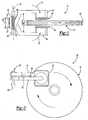
- a self-energizing brake assembly 10 includes first and second calipers 14, 18 pivotally attached to a support 26.
- the calipers 14, 18 engage a rotor 12.
- the contact surface between the calipers 14, 18 and the rotor 12 is formed by friction material 24. Frictional contact between the calipers 14, 18 causes a rotation toward the rotor 12 in a direction indicated by arrows 15 that magnifies braking force applied to the rotor 12.
- a first pivot 20 supports the first caliper 14 and a second pivot 16 supports the second caliper 18.
- a distance 36 between each of the pivots 16, 20 is adjustable.
- An actuator 30 is used to adjust the distance 36 between the pivots 16, 20. Friction between the calipers 14, 18 and the rotor 12 pulls the calipers 14,18 in the direction of rotation of the rotor 12. The offset position of the pivots 16, 20 causes each caliper 14,18 to be pulled in the direction of rotation of the rotor 12.
- the pivots 16, 20 are located on an opposite side of the contact surface that the corresponding caliper 14, 18 engages. Frictional force between the rotor 12 and the calipers 14, 18 causes an increase in the magnitude of force gain exerted to stop rotation of the rotor 12.
- the pivots 16, 20 are movable linearly relative to each other within a common plane 32.
- the first pivot 20 is disposed on an opposite side of centerline 38 relative to the first caliper 14.
- the position opposite the centerline 38 creates the rotation moment 15 that pulls the caliper 14 into the rotor 12.
- the second pivot 16 is on an opposite side of the centerline 38 relative to the second caliper 18, causing the second caliper 18 to be pulled into the rotor 12.
- the pivots 16, 20 are on an opposite side of the centerline 38, the pivots 16, 20 need only be on an opposite side of the contact surface between the rotor and the corresponding caliper 14, 18.
- a distance 37 between the centerline 38 and each of the pivots 16, 20 is uniform creating a uniform balanced force between the calipers 14, 18 as each is pulled into the rotor 12.
- the pivots 16,20 are biased toward each other by a spring 28.
- a spring is described, other biasing devices as are known to a worker skilled in the art, are within the contemplation of this invention.
- the pivots 16, 20 move along the support 26 within the common plane 32 in response to movement of the actuator 30.
- the force gain realized is a factor of the friction force between the rotor 12 and each caliper 14, 18 and the position of the pivots 16, 20.
- the friction force is dependent on material properties of the friction material 24 and the rotor 12, the force exerted to engage the rotor 12 with the calipers 14, 18, and the position of the pivots 16, 20.
- the distance 36 between the pivots 16, 20 is adjusted to control the force gain. As the distance 36 increases, the gain in force from self-energization increases, because the rotational moment is magnified. Decreasing the distance 36 decreases the magnitude of force gain from self-energization.
- the actuator 30 adjusts the distance 36 between the calipers 14, 18 to control the magnitude of force gain.
- the distance 36 correlates to a difference between the contact surface of the rotor 12 and each of the pivots 16, 20.
- the distance between the contact surface and the pivots 16, 20 generate the gains in braking force. Control of the force gain of the self-energized brake assembly 10 prevents lock up conditions and provides for uniform control of braking forces.
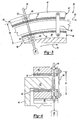
- another self-energized brake assembly 40 includes first and second brake pads 44, 48 pivotally attached to a hinge 58.
- the first and second brake pads 44, 48 move between an applied position and a released position.
- the first and second brake pads 44, 48 engage a rotor 42 in the applied position.
- the rotor 42 includes a flange 43 extending transverse to rotation of the rotor 42.
- the brake pads 44, 48 are disposed on opposite sides of the flange 43.
- An electric motor 56 rotates a threaded rod 54 to move the brake pads 44, 48 between the applied and released positions.
- the threaded rod 54 is threadingly engaged to internal threads 62 disposed on each of the brake pads 44, 48.
- the internal threads 68 may either be a separate component, such as a nut, or an integral feature of each brake pad 44, 48. Rotation of the threaded rod 54 changes a distance 60 between the brake pads 44, 48 such that the friction material 52 engages the rotor flange 43 of the rotor 42.
- Rotation of the threaded rod 54 by the drive 56 causes movement of the brake pads 44, 48 into initial contact with the flange 43.
- a frictional force generated by the interaction between the brake pads 44,48 and the flange 43 in the direction indicated by arrow 53 pulls the brake pads 44, 48 in the direction of rotation 45 of the rotor 42.
- the braking force required to control rotation of the rotor 42 is generated by the frictional forces pulling the brake pads 44, 48 into contact with the rotor 42 with increasing force.
- the motor 54 need not generate all of the braking force required to control rotation of the rotor 42.
- the electric motor 56 requires only enough power to apply sufficient force between the brake pads 44, 48 and the rotor 42 to initiate brake self-energization.
- Each brake pad 44, 48 includes a segment 68.
- the internal thread 62 is disposed adjacent the segment 68 and allows some rotation about pivot points 63 of the brake pads 44, 48 relative to the threaded rod 54.
- the hinge 58 is pivotally attached adjacent a segment 67 distal from the segment 68.
- a self-energized brake assembly 40' includes a second electric motor 56' and threaded rod 54'.
- the second motor 56' and threaded rod 54' provide for movement of the end 67 of each of the brake pads 44,48. Movement of the brake pads 44, 48 from the end 67 accommodates rotation of the rotor 42 in a reverse direction.
- one of the electric motors 56, 56' is actuated to draw in and engage the brake pads 44, 48 with the rotor 42.
- the direction of the rotor 42 determines which of the motors 56, 56' is actuated.
- the motor 56, 56' not actuated maintains position of the corresponding threaded rod 54, 54' to maintain position of the brake pads 44, 48 and generate the desired gain in braking force.
- another self-energized brake assembly 70 designed according to this invention includes first and second parallel pivot arms 80, 84.
- the pivot arms 80, 84 are pivotally attached at a first segment 86 to a caliper housing 78 and at a second segment 90 to first brake pad 74.
- a second brake pad 76 also includes first and second pivot arms 81, 83 pivotally attached at one segment to the housing 78 and at another segment to the brake pad 76.
- Each brake pad 74, 76 includes friction material 82 which contacts a rotor 72.
- the complimentary brake pads 74, 76 are preferably symmetrical about a rotor centerline.
- An actuator 92 includes actuation arms 94 attached to drive the brake pads 74,76 between an applied and released position.
- Each pivot arm 80,81,83 and 84 includes a first pivotal connection 86 disposed on the support 78 and a second pivotal connection 90 disposed on the brake pads 74,76.
- the first pivotal connection 86 is disposed on a plane defined by a centerline 88 of the rotor 72.
- Engaging the rotor 72 with the brake pads 74, 76 increases braking force above that exerted by the actuator 92 by pulling the brake pads 74, 76 in the direction of rotation of the rotor 72.
- a distance between each of the brake pads 74, 76 decreases because the pivot arms 80,81,83 and 84 are of fixed length 98 that translates movement in the direction of rotation into movement toward the rotor 72.
- Each of the pivot arms 80, 81, 83 and 84 are of a common length 98.
- the pivot arms 80,81,83 and 84 are disposed parallel to each other and are attached along the centerline 88 of the rotor 72 to produce forces that pull the pads 74 and 76 inward toward the rotor 72.
- An angle 99 at which the pivot arms 80,81, 83 and 84 are disposed when the brake pads 74, 76 engage the rotor 72 controls the increase in braking force due to self-energization. The smaller the angle the greater the increase in braking force.
- the actuator 92 drives the actuation arms 94 to move the brake pads 74, 76 into initial engagement with the rotor 72.
- the actuator 92 is preferably a linear motor, however, a worker skilled in the art with the benefit of the teachings of this disclosure will understand that other known actuators are within the contemplation of this invention.
- Increasing the angle 99 at which the brake pads engage the rotor 72 compensates for wear of the friction material 82.
- the common length of pivot arms 80, 81, 83, and 84 on either side of the rotor 72 exert a symmetrical braking force on the rotor 72.
- the symmetrical braking force on the rotor 72 allows for the use of a fixed caliper housing 78.
- FIG. 8 another embodiment of the brake assembly includes pivot arms 80', 81', 83' and 84' that have an adjustable length 98'.
- Each of the pivot arms 80', 81', 83' and 84' includes an adjustable member 85.
- the adjustable member 85 is preferably a spring that provide for changes in the length 98' of each pivot arm 80', 81', 83' and 84'.
- the changes in length 98' provide additional braking force gain by allowing for further decreases in angle 99.
- the decrease in the angle 99 corresponds with increased gains in the braking forces exerted on the rotor 72.
- the pivot arms 80', 81', 83' and 84' rotate into contact with the rotor 72 at an angle 99.
- the angle 99 corresponds to the gain in braking force resulting from self-energization.
- the adjustable member 85 allows an increase in length 98' of each pivot arm 80', 81', 83' and 84' that allows a further decrease in angle 99, which in turn corresponds to a further increase in braking force.
- the expandable length 99 allows for the use of shorter pivot arms 80', 81', 83' and 84' while obtaining gains that would only otherwise be available with fixed pivot arms of lesser length.
- another a self-energized brake assembly 100 includes pivot arms 110 attached at one segment to a caliper housing 126 and at a second segment to a brake pad 116.
- Each of the pivot arms 110 have a common length forming a parallelogram with each brake pad 116.
- First and second motors 106, 108 drive ball screws 118 toward and away from a rotor 104.
- the motors 108, 106 are attached to an outer caliper housing 102 and are actuatable to bring each of the brake pads 116 into engagement with the rotor 104.
- the brake pads 116 contact the rotor 104 and are pulled in the direction of rotor rotation 125.
- the pivot arms 110 translate movement of the brake pads 116 in the direction of rotation 125 into movement of the brake pads 116 toward the rotor 104 to increase braking forces independent of force exerted by the motors 106, 108.
- the pivot arms 110 are attached at a first pivot 112 supported on the caliper housing 126.
- the first pivot 112 is spaced from a centerline 124 of the rotor 104.
- Individual motor actuation applies force to each of the brake pads 116 to provide the desired self-energization gains.
- the use of individual motors 106, 108 provides for the variation in the applied force exerted on each brake pad 116 to accommodate and adjust for differing amounts of wear. Further, the use of two individually actuated motors 106, 108 provides for a fixed outer caliper housing 102.
- another self-energizing brake assembly 130 includes a single link 156 pivotally attached to first and second brake pads 138, 142.
- Each brake pad 138, 142 includes friction material 140 comprising a surface engaging a rotor 136.
- the link 156 is pivotally attached at a pivot 150 disposed on a caliper housing 134. Pivots 154 and 152 attach the link 156 to the first and second brake pads 142, 138.
- the pivot 150 is disposed within a slot 151 and is movable across the centerline 144 of the rotor 136.
- Rotation of the link 156 shown by arrows 158 move the brake pads 138,142 between an applied and release position with the rotor 136. Friction between the brake pads 138, 142 and rotor 136 create the wedging action that drives the brake pads 138,142 into the rotor 136. Spacing between the pivots 150, 154, and 156 provides an additional adjustment to affect the amount of self-energizing force applied to increase braking force.
- An actuator 158 rotates the lever 156 and thereby the brake pads 138, 142 into engagement with the rotor 136.
- the friction force in the direction of rotation of the rotor 136 causes further rotation of the brake pads toward the rotor 136, causing an increase and multiplication of applied braking force.
- the lever 156 is moved toward a center position to rotate the brake pads 138, 140 away from the rotor 136 to disengage and release the rotor 136. Further, the actuator 158 rotates the lever 156 in either direction to accommodate braking with the rotor 140 rotating in an opposite direction. Increases in braking force are only provided by creating a force to pull the brake pads 138, 142 into the rotor 136.
- the actuator 158 rotates the lever 156 in a direction causing frictional engagement between the brake pads 138 and the rotor 136.
- a further increase in braking force is provided by self-energization caused by forcing the brake pads 138, 142 into further contact with the rotor 136.
- another self-energized brake actuator 170 includes a first brake pad 188 fixed to a sliding caliper 172.
- a second brake pad 186 is pivotally attached to the first brake pad 188 by first and second pivot arms 178, 180.
- the pivot arms 178, 180 are pivotally attached to the first brake pad 188 at pivots 190 and to the second brake pad 186 at a pivot 184.
- the second brake pad 186 rotates in the direction 192 in response to actuation of the lever 174.
- An actuator 194 applies a force to the lever 174 to move the brake pads 188, 186 into contact with the rotor 176.
- the actuator 194 is preferably a linear electric motor, however any actuator known to a worker skilled in the art is within the contemplation of this invention.
- Friction material 198 on each of the brake pads 188,186 forms the contact surface with the rotor 176.
- Rotation of the lever 174 by the actuator 194 causes engagement of the second brake pad 186 with the rotor 176.
- the sliding motion of the second brake pad 186 shortens the distance between brake pads 188,186 causing contact with the rotor 176.
- Engagement of the rotor 176 causes sliding of the second brake pad 186 and a further decrease in distance between first and second brake pads 188, 186.
- the brake pads 188,186 rotate into contact with the rotor 176 with an increasing amount of force. The increased force originates from the forces of the rotating rotor 176.
- the brake actuators designed according to this invention control gains in braking forces obtained through self-generation and reduce the magnitude of force required to be applied by a brake actuator. Reducing the amount of applied force required provides for the use of electric actuators of smaller sizes and power requirements to overcome weight and power restrictions that would otherwise make electric brake actuation unfeasible.
Landscapes
- Engineering & Computer Science (AREA)
- General Engineering & Computer Science (AREA)
- Mechanical Engineering (AREA)
- Braking Arrangements (AREA)
Claims (7)
- Selbstverstärkte Bremseinheit (10), die Folgendes umfasst:ein drehbares Bremselement (12), das innerhalb einer Rotationsebene drehbar ist;einen ersten Arm, der um eine erste Schwenkachse (20) schwenkbar befestigt ist, wobei sich die erste Schwenkachse auf einer gegenüberliegenden Seite einer Kontaktoberfläche des ersten Arms mit dem drehbaren Element vom ersten Arm befindet;einen zweiten Arm, der um eine zweite Schwenkachse (16) schwenkbar befestigt ist, wobei sich die zweite Schwenkachse auf einer gegenüberliegenden Seite einer Kontaktoberfläche des zweiten Arms mit dem drehbaren Element vom zweiten Arm befindet, und wobei die zweite Schwenkachse mit einer Distanz von der ersten Schwenkachse beabstandet ist; gekennzeichnet durchein Einstellelement, um die Bremskraftzunahme durch Selbstverstärkung durch Einstellen der Distanz (36) zwischen der ersten und der zweiten Schwenkachse zu kontrollieren.
- Selbstverstärkte Bremseinheit (10) nach Anspruch 1, bei der der erste Arm ein erster Bremssattel (14) und der zweite Arm ein zweiter Bremssattel (18) sind.
- Einheit nach Anspruch 1 oder Anspruch 2, die ein Vorspannelement umfasst, das sich zwischen dem ersten Arm und dem zweiten Arm befindet, um die erste Schwenkachse und die zweite Schwenkachse zueinander vorzuspannen.
- Einheit nach Anspruch 1, 2 oder 3, bei der das Einstellelement eine Feder (28) ist, die vorgesehen ist, um die erste Schwenkachse und die zweite Schwenkachse zueinander vorzuspannen.
- Einheit nach Anspruch 1, 2, 3 oder 4, die einen Betätiger (30) umfasst, um die Distanz zwischen der ersten Schwenkachse und der zweiten Schwenkachse einzustellen.
- Einheit nach Anspruch 1, 2, 3, 4 oder 5, bei der sich die erste Schwenkachse (20) und die zweite Schwenkachse (16) auf einer gemeinsamen Ebene (32) befinden und entlang der gemeinsamen Ebene bewegbar sind, um die auf das drehbare Bremselement ausgeübte Bremskraft einzustellen.
- Einheit nach Anspruch 2, bei der das drehbare Bremselement (12) eine Mittellinie (38) hat, und wobei sich die erste Schwenkachse (20) auf einer gegenüberliegenden Seite der Mittellinie (38) im Verhältnis zum ersten Bremssattel (14) und die zweite Schwenkachse auf einer gegenüberliegenden Seite der Mittellinie (38) im Verhältnis zum zweiten Bremssattel (18) befinden.
Applications Claiming Priority (2)
| Application Number | Priority Date | Filing Date | Title |
|---|---|---|---|
| US747746 | 1985-06-24 | ||
| US10/747,746 US7055658B2 (en) | 2003-12-29 | 2003-12-29 | Gain stabilizing self-energized brake mechanism |
Publications (3)
| Publication Number | Publication Date |
|---|---|
| EP1550816A2 EP1550816A2 (de) | 2005-07-06 |
| EP1550816A3 EP1550816A3 (de) | 2006-07-26 |
| EP1550816B1 true EP1550816B1 (de) | 2014-09-24 |
Family
ID=34574749
Family Applications (1)
| Application Number | Title | Priority Date | Filing Date |
|---|---|---|---|
| EP04258146.2A Expired - Lifetime EP1550816B1 (de) | 2003-12-29 | 2004-12-24 | Bremsmechanismus mit stabilisierter Selbstverstärkung |
Country Status (2)
| Country | Link |
|---|---|
| US (2) | US7055658B2 (de) |
| EP (1) | EP1550816B1 (de) |
Families Citing this family (15)
| Publication number | Priority date | Publication date | Assignee | Title |
|---|---|---|---|---|
| DE502006003271D1 (de) * | 2006-08-18 | 2009-05-07 | Brainlab Ag | Adapter zur Anbringung einer Referenzanordnung an ein medizinisches Instrument, das eine funktionale Richtung bzw. Ebene aufweist |
| GB0616589D0 (en) * | 2006-08-21 | 2006-09-27 | Instron Ltd | Linear motor brake |
| WO2009129764A1 (de) * | 2008-04-24 | 2009-10-29 | Martin Stadlmeier | Elektrisch regelbare scheibenbremse |
| US8820490B2 (en) | 2012-03-16 | 2014-09-02 | Arvinmeritor Technology, Llc | Manual adjuster for automatic slack adjuster |
| AT512683B1 (de) * | 2012-04-12 | 2024-12-15 | Bosch Gmbh Robert | Bremssystem und Bremsverfahren für eine elektrisch betätigte, nicht-lineare Reibungsbremse |
| CN102817937B (zh) * | 2012-07-03 | 2016-02-24 | 中国石油大学(华东) | 一种自增力盘式制动器 |
| EP2781783A1 (de) * | 2013-03-15 | 2014-09-24 | Siemens Aktiengesellschaft | Mobile Bremsvorrichtung |
| US9022179B2 (en) * | 2013-10-07 | 2015-05-05 | Bendix Spicer Foundation Brake Llc | Rotary lever disc brake caliper with rack and pinion mechanism |
| KR101509976B1 (ko) | 2013-11-20 | 2015-04-07 | 현대자동차주식회사 | 전동식 멀티 패드 브레이크 |
| JP2019043227A (ja) * | 2017-08-30 | 2019-03-22 | 株式会社シマノ | ブレーキ装置および電動ブレーキシステム |
| KR101977322B1 (ko) | 2018-10-22 | 2019-05-10 | 경창산업주식회사 | 자기 강화 브레이크 캘리퍼 |
| KR102043696B1 (ko) * | 2019-01-16 | 2019-11-12 | 경창산업주식회사 | 자기 강화 브레이크 캘리퍼 |
| CN110081012A (zh) * | 2019-04-17 | 2019-08-02 | 江苏常熟发电有限公司 | 吸风机转子制动装置 |
| US12031596B2 (en) * | 2021-01-22 | 2024-07-09 | Kwangjin Michael Lee | Direct-acting self-energizing brake caliper |
| CN114734672B (zh) * | 2022-06-10 | 2022-08-26 | 浙江易锻精密机械有限公司 | 一种冲压设备 |
Family Cites Families (30)
| Publication number | Priority date | Publication date | Assignee | Title |
|---|---|---|---|---|
| US1267133A (en) * | 1916-10-04 | 1918-05-21 | Eugene H H Smith | Pliers. |
| US2274945A (en) * | 1939-07-19 | 1942-03-03 | Marie S Van Keuren | Pliers |
| US2527072A (en) * | 1946-06-03 | 1950-10-24 | American Brake Shoe Co | Rim grip brake |
| US2590062A (en) * | 1946-07-05 | 1952-03-18 | American Steel Foundries | Brake head mounting |
| GB952612A (en) * | 1959-08-29 | 1964-03-18 | Dunlop Rubber Co | Improvements in disc brakes |
| US3003589A (en) * | 1960-08-22 | 1961-10-10 | Azusa Engineering Inc | Vehicular brake |
| US3207267A (en) * | 1961-03-21 | 1965-09-21 | Teves Kg Alfred | Self-energizing disk brake |
| GB1106387A (en) * | 1963-11-12 | 1968-03-13 | Dunlop Rubber Co | Disc brakes |
| US3465849A (en) * | 1968-03-15 | 1969-09-09 | Moe M Bernfeld | Alligator clamp disc brake |
| US3592300A (en) * | 1969-10-31 | 1971-07-13 | Gen Motors Corp | Self-energizing disc brake |
| US3749206A (en) * | 1971-12-09 | 1973-07-31 | Clark Equipment Co | Self-energized disc brake mechanism |
| DE2257452A1 (de) * | 1972-11-23 | 1974-05-30 | Wilhelm E Frede | Bremsvorrichtung |
| US3921764A (en) * | 1973-07-25 | 1975-11-25 | William R Mathauser | Self-energizing bicycle brake |
| FR2334884A1 (fr) * | 1975-10-16 | 1977-07-08 | Pascal Jean Pierre | Pince pour frein a disque |
| JPS5560737A (en) * | 1978-10-30 | 1980-05-08 | Akebono Brake Ind Co Ltd | Disc brake |
| US4827930A (en) * | 1982-06-28 | 1989-05-09 | Codman & Shurtleff, Inc. | Reinforcing closer for aneurysm clip |
| JPS5993527A (ja) * | 1982-11-18 | 1984-05-30 | Nissan Motor Co Ltd | デイスクブレ−キ |
| DE3326374A1 (de) * | 1983-07-21 | 1985-01-31 | Knorr-Bremse GmbH, 8000 München | Bremsgestaenge fuer fahrzeugreibungsbremsen |
| US4854425A (en) | 1984-11-05 | 1989-08-08 | Servadio Robert | Self-energizing disc brake shoe |
| DE3502560A1 (de) * | 1985-01-25 | 1986-07-31 | Knorr-Bremse AG, 8000 München | Bremsgestaenge fuer fahrzeugbremsen |
| US4646007A (en) * | 1985-03-25 | 1987-02-24 | Faria Thomas G | Tachometer indicator with uncompensated magnetic return to zero |
| US4946007A (en) | 1987-11-03 | 1990-08-07 | Pedersen Development Co. | Self-energizing brake |
| US4974704A (en) | 1987-11-03 | 1990-12-04 | Pedersen Development Corporation | Self-energizing disc/rotor or rim brake |
| DE3900740A1 (de) | 1989-01-12 | 1990-07-19 | Teves Gmbh Alfred | Vorrichtung fuer eine trommelbremse, insbesondere fuer mechanisch betaetigbare selbstverstaerkende innenbackentrommelbremsen fuer kraftfahrzeuge |
| US5390986A (en) | 1993-03-09 | 1995-02-21 | General Motors Corporation | Self-energizing vehicular brake system with electronically actuated hydraulic balance forces |
| JPH07224866A (ja) * | 1994-02-10 | 1995-08-22 | Toyota Motor Corp | サーボディスクブレーキ |
| US5775782A (en) | 1996-02-23 | 1998-07-07 | Imra America, Inc. | Self-energizing vehicle brake system with control arrangement for eliminating brake pad friction fluctuation affects |
| US5921354A (en) * | 1996-05-07 | 1999-07-13 | Kelsey-Hayes Company | Self-energizing anti-creep parking and emergency brake mechanism for disc brake assembly |
| DE19819564C2 (de) | 1998-04-30 | 2000-06-08 | Deutsch Zentr Luft & Raumfahrt | Elektromechanische Bremse mit Selbstverstärkung |
| DE29901831U1 (de) * | 1999-02-03 | 1999-05-06 | Quenstedt, Jan, Dipl.-Ing., 52152 Simmerath | Backenbremse mit Servoeffekt |
-
2003
- 2003-12-29 US US10/747,746 patent/US7055658B2/en not_active Expired - Fee Related
-
2004
- 2004-12-24 EP EP04258146.2A patent/EP1550816B1/de not_active Expired - Lifetime
-
2006
- 2006-05-26 US US11/441,870 patent/US20060213729A1/en not_active Abandoned
Also Published As
| Publication number | Publication date |
|---|---|
| EP1550816A2 (de) | 2005-07-06 |
| US20060213729A1 (en) | 2006-09-28 |
| US7055658B2 (en) | 2006-06-06 |
| EP1550816A3 (de) | 2006-07-26 |
| US20050139435A1 (en) | 2005-06-30 |
Similar Documents
| Publication | Publication Date | Title |
|---|---|---|
| US7055658B2 (en) | Gain stabilizing self-energized brake mechanism | |
| EP1550817B1 (de) | Vorrichtung zur Stabilisierung der Verstärkung einer selbstversärkenden Scheibenbremse | |
| CN1299023C (zh) | 无间隙操纵式电动机械制动器 | |
| US9989115B2 (en) | Disc brake system | |
| US4116307A (en) | Fluid pressure operated disc brake having service, auxiliary and parking brake systems | |
| CN1056220C (zh) | 机械致动的鼓式制动器 | |
| KR101977322B1 (ko) | 자기 강화 브레이크 캘리퍼 | |
| US20040238294A1 (en) | Friction brake with mechanical self-boosting and method for its actuation | |
| KR100396244B1 (ko) | 드럼브레이크를위한기계식작동장치 | |
| US20030116389A1 (en) | Electromechanical parking brake | |
| WO2019073786A1 (ja) | フローティングキャリパタイプのディスクブレーキ装置 | |
| KR20070022336A (ko) | 셀프-에너자이징 전기 기계식 마찰 브레이크 | |
| US4274513A (en) | Disc brake and actuating lever therefor | |
| JPH0379575B2 (de) | ||
| US2959253A (en) | Disk brake | |
| US3768601A (en) | Disc brake and adjusting device therefor | |
| US3294200A (en) | Adjustment device for disc brakes | |
| US3388776A (en) | Transversely movable, opposing, rim grip brake | |
| US4344510A (en) | Disc brake and improved adjuster therefor | |
| US4903800A (en) | Self-adjusting drum brake | |
| WO2007148227A1 (en) | Disk brakes | |
| EP3336374B1 (de) | Mechanische bremse | |
| JPS6113784Y2 (de) | ||
| EP4722556A1 (de) | Bremsanordnung für ein schienenfahrzeug | |
| WO2019131676A1 (ja) | フローティングキャリパタイプのディスクブレーキ装置 |
Legal Events
| Date | Code | Title | Description |
|---|---|---|---|
| PUAI | Public reference made under article 153(3) epc to a published international application that has entered the european phase |
Free format text: ORIGINAL CODE: 0009012 |
|
| AK | Designated contracting states |
Kind code of ref document: A2 Designated state(s): AT BE BG CH CY CZ DE DK EE ES FI FR GB GR HU IE IS IT LI LT LU MC NL PL PT RO SE SI SK TR |
|
| AX | Request for extension of the european patent |
Extension state: AL BA HR LV MK YU |
|
| PUAL | Search report despatched |
Free format text: ORIGINAL CODE: 0009013 |
|
| AK | Designated contracting states |
Kind code of ref document: A3 Designated state(s): AT BE BG CH CY CZ DE DK EE ES FI FR GB GR HU IE IS IT LI LT LU MC NL PL PT RO SE SI SK TR |
|
| AX | Request for extension of the european patent |
Extension state: AL BA HR LV MK YU |
|
| 17P | Request for examination filed |
Effective date: 20070124 |
|
| AKX | Designation fees paid |
Designated state(s): DE FR GB IT SE |
|
| 17Q | First examination report despatched |
Effective date: 20110118 |
|
| GRAP | Despatch of communication of intention to grant a patent |
Free format text: ORIGINAL CODE: EPIDOSNIGR1 |
|
| INTG | Intention to grant announced |
Effective date: 20140411 |
|
| GRAS | Grant fee paid |
Free format text: ORIGINAL CODE: EPIDOSNIGR3 |
|
| GRAA | (expected) grant |
Free format text: ORIGINAL CODE: 0009210 |
|
| AK | Designated contracting states |
Kind code of ref document: B1 Designated state(s): DE FR GB IT SE |
|
| REG | Reference to a national code |
Ref country code: GB Ref legal event code: FG4D |
|
| REG | Reference to a national code |
Ref country code: DE Ref legal event code: R096 Ref document number: 602004045876 Country of ref document: DE Effective date: 20141030 |
|
| REG | Reference to a national code |
Ref country code: SE Ref legal event code: TRGR |
|
| PGFP | Annual fee paid to national office [announced via postgrant information from national office to epo] |
Ref country code: GB Payment date: 20141229 Year of fee payment: 11 |
|
| REG | Reference to a national code |
Ref country code: DE Ref legal event code: R097 Ref document number: 602004045876 Country of ref document: DE |
|
| PLBE | No opposition filed within time limit |
Free format text: ORIGINAL CODE: 0009261 |
|
| STAA | Information on the status of an ep patent application or granted ep patent |
Free format text: STATUS: NO OPPOSITION FILED WITHIN TIME LIMIT |
|
| PG25 | Lapsed in a contracting state [announced via postgrant information from national office to epo] |
Ref country code: IT Free format text: LAPSE BECAUSE OF FAILURE TO SUBMIT A TRANSLATION OF THE DESCRIPTION OR TO PAY THE FEE WITHIN THE PRESCRIBED TIME-LIMIT Effective date: 20140924 |
|
| 26N | No opposition filed |
Effective date: 20150625 |
|
| REG | Reference to a national code |
Ref country code: FR Ref legal event code: PLFP Year of fee payment: 12 |
|
| GBPC | Gb: european patent ceased through non-payment of renewal fee |
Effective date: 20151224 |
|
| PG25 | Lapsed in a contracting state [announced via postgrant information from national office to epo] |
Ref country code: GB Free format text: LAPSE BECAUSE OF NON-PAYMENT OF DUE FEES Effective date: 20151224 |
|
| REG | Reference to a national code |
Ref country code: FR Ref legal event code: PLFP Year of fee payment: 13 |
|
| PGFP | Annual fee paid to national office [announced via postgrant information from national office to epo] |
Ref country code: SE Payment date: 20161129 Year of fee payment: 13 Ref country code: FR Payment date: 20161227 Year of fee payment: 13 |
|
| PGFP | Annual fee paid to national office [announced via postgrant information from national office to epo] |
Ref country code: DE Payment date: 20161229 Year of fee payment: 13 |
|
| REG | Reference to a national code |
Ref country code: DE Ref legal event code: R119 Ref document number: 602004045876 Country of ref document: DE |
|
| PG25 | Lapsed in a contracting state [announced via postgrant information from national office to epo] |
Ref country code: SE Free format text: LAPSE BECAUSE OF NON-PAYMENT OF DUE FEES Effective date: 20171225 |
|
| REG | Reference to a national code |
Ref country code: FR Ref legal event code: ST Effective date: 20180831 |
|
| PG25 | Lapsed in a contracting state [announced via postgrant information from national office to epo] |
Ref country code: DE Free format text: LAPSE BECAUSE OF NON-PAYMENT OF DUE FEES Effective date: 20180703 Ref country code: FR Free format text: LAPSE BECAUSE OF NON-PAYMENT OF DUE FEES Effective date: 20180102 |