EP1550498A2 - Cartouche de réactifs avec des récipients pour réactifs contenant des particules pour leur homegénéisation non invasive - Google Patents
Cartouche de réactifs avec des récipients pour réactifs contenant des particules pour leur homegénéisation non invasive Download PDFInfo
- Publication number
- EP1550498A2 EP1550498A2 EP04029815A EP04029815A EP1550498A2 EP 1550498 A2 EP1550498 A2 EP 1550498A2 EP 04029815 A EP04029815 A EP 04029815A EP 04029815 A EP04029815 A EP 04029815A EP 1550498 A2 EP1550498 A2 EP 1550498A2
- Authority
- EP
- European Patent Office
- Prior art keywords
- cassette
- container
- reagent
- particle
- containers
- Prior art date
- Legal status (The legal status is an assumption and is not a legal conclusion. Google has not performed a legal analysis and makes no representation as to the accuracy of the status listed.)
- Granted
Links
Images


Classifications
-
- B—PERFORMING OPERATIONS; TRANSPORTING
- B01—PHYSICAL OR CHEMICAL PROCESSES OR APPARATUS IN GENERAL
- B01L—CHEMICAL OR PHYSICAL LABORATORY APPARATUS FOR GENERAL USE
- B01L3/00—Containers or dishes for laboratory use, e.g. laboratory glassware; Droppers
- B01L3/50—Containers for the purpose of retaining a material to be analysed, e.g. test tubes
- B01L3/508—Containers for the purpose of retaining a material to be analysed, e.g. test tubes rigid containers not provided for above
-
- B—PERFORMING OPERATIONS; TRANSPORTING
- B01—PHYSICAL OR CHEMICAL PROCESSES OR APPARATUS IN GENERAL
- B01F—MIXING, e.g. DISSOLVING, EMULSIFYING OR DISPERSING
- B01F29/00—Mixers with rotating receptacles
- B01F29/30—Mixing the contents of individual packages or containers, e.g. by rotating tins or bottles
- B01F29/32—Containers specially adapted for coupling to rotating frames or the like; Coupling means therefor
- B01F29/322—Containers specially adapted for coupling to rotating frames or the like; Coupling means therefor of two or more containers supported for simultaneous mixing, e.g. for bottles in crates
-
- B—PERFORMING OPERATIONS; TRANSPORTING
- B01—PHYSICAL OR CHEMICAL PROCESSES OR APPARATUS IN GENERAL
- B01F—MIXING, e.g. DISSOLVING, EMULSIFYING OR DISPERSING
- B01F23/00—Mixing according to the phases to be mixed, e.g. dispersing or emulsifying
- B01F23/02—Maintaining the aggregation state of the mixed materials
- B01F23/023—Preventing sedimentation, conglomeration or agglomeration of solid ingredients during or after mixing by maintaining mixed ingredients in movement
-
- B—PERFORMING OPERATIONS; TRANSPORTING
- B01—PHYSICAL OR CHEMICAL PROCESSES OR APPARATUS IN GENERAL
- B01F—MIXING, e.g. DISSOLVING, EMULSIFYING OR DISPERSING
- B01F23/00—Mixing according to the phases to be mixed, e.g. dispersing or emulsifying
- B01F23/50—Mixing liquids with solids
- B01F23/53—Mixing liquids with solids using driven stirrers
-
- B—PERFORMING OPERATIONS; TRANSPORTING
- B01—PHYSICAL OR CHEMICAL PROCESSES OR APPARATUS IN GENERAL
- B01F—MIXING, e.g. DISSOLVING, EMULSIFYING OR DISPERSING
- B01F29/00—Mixers with rotating receptacles
- B01F29/10—Mixers with rotating receptacles with receptacles rotated about two different axes, e.g. receptacles having planetary motion
-
- B—PERFORMING OPERATIONS; TRANSPORTING
- B01—PHYSICAL OR CHEMICAL PROCESSES OR APPARATUS IN GENERAL
- B01F—MIXING, e.g. DISSOLVING, EMULSIFYING OR DISPERSING
- B01F35/00—Accessories for mixers; Auxiliary operations or auxiliary devices; Parts or details of general application
- B01F35/50—Mixing receptacles
-
- B—PERFORMING OPERATIONS; TRANSPORTING
- B01—PHYSICAL OR CHEMICAL PROCESSES OR APPARATUS IN GENERAL
- B01F—MIXING, e.g. DISSOLVING, EMULSIFYING OR DISPERSING
- B01F35/00—Accessories for mixers; Auxiliary operations or auxiliary devices; Parts or details of general application
- B01F35/56—General build-up of the mixers
- B01F35/561—General build-up of the mixers the mixer being built-up from a plurality of modules or stacked plates comprising complete or partial elements of the mixer
-
- G—PHYSICS
- G01—MEASURING; TESTING
- G01N—INVESTIGATING OR ANALYSING MATERIALS BY DETERMINING THEIR CHEMICAL OR PHYSICAL PROPERTIES
- G01N35/00—Automatic analysis not limited to methods or materials provided for in any single one of groups G01N1/00 - G01N33/00; Handling materials therefor
- G01N2035/00465—Separating and mixing arrangements
- G01N2035/00524—Mixing by agitating sample carrier
Definitions
- the invention relates to a reagent cartridge with a reagent container for a particle-containing reagent, which is particularly suitable for noninvasive Homogenization of coated and sedimenting particles as well as a magazine.
- Diagnostic assay systems often involve the use of particles in a liquid for the course of reactions. These are procedures for Detection of chemical binding reactions, for example in connection with Antigens or antibodies. For the correct processing of assays on this Systems, it is usually required that the particles in the associated containers have as homogeneous a distribution as possible at the time of removal. A homogeneous particle distribution avoids, for example, sedimentation processes occurring concentration differences between successive withdrawals the containers.
- Rotating paddles are used. Such rotatably received paddles are known from EP 0 745 855 and US 6,772,962. Furthermore, intermittently rotating round plastic bottles are used, which are equipped with radial inner fins, as for example US 5,637,275, US 5,795,784 or US 5,856,194 can be removed.
- Ultrasonic methods are known in which an ultrasonically excited dispensing needle in the liquid is immersed and mixed. Such solutions can, for example US Pat. No. 5,658,799, EP 0 580 483 or US Pat. No. 5,985,672.
- the advantages of the proposed solution according to the invention are that through the proposed non-invasive homogenization of the particle-laden liquid Carryover risk can definitely be ruled out. It does not need any Washing stations. Furthermore, no washing fluid is required and finally no Liquid waste that must be disposed of in compliance with legal regulations. Furthermore, an extremely low dead volume can be achieved, making the reagent better can be exploited as a foaming, as to those of the prior art sketched known processes, omitted.
- the solution proposed according to the invention also allows greater freedom in system design and provides the opportunity the parallelization of accesses in the reagent area, because of several reagents containing container of a container unit can be accessed. The parallelization also allows significantly shorter process times for homogenization compared with a sequential processing.
- the inventively proposed, plug-in cassette also provides the Advantage that Deckelö Stamms- and lid closing processes during homogenization now can be omitted.
- the inventively proposed pluggable reagent cassette also sets inexpensive, producible in mass production plastic component, which is a simple Cassette assembly allows. This is how a cassette assembly can be in that two buckled Klipsmaschine including a container containing particle-laden reagents are simply plugged together can.
- the clip-on clip parts are large and flat surfaces, which greatly simplify labeling.
- the individual clip parts as well as the container, which absorbs the particle-laden liquid, can be independent of time be filled from each other.
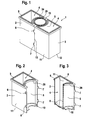
- FIG. 1 The representation according to FIG. 1 is a prefabricated, still open on its upper side Reagent cassette according to the present invention can be seen.
- a reagent cartridge 1 is formed by a first cassette part 2 forming a container and a second, also a container forming cassette part 3 is formed.
- the Container-forming cassette parts 2, 3 are at their facing sides respectively provided with a vault 5. Between the vaults 5 of the cassette parts 2, 3 is located a container 20 (bead bottle).
- the container 20 has at its top one as Welding surface formed annular surface 24, as well as the container forming Cartridge parts 2, 3 have a welding surface 9 on its upper side.
- the container 20 serves to receive a particle-containing reagent, while in cavities 4 of the container forming cassette parts 2, 3 are provided as liquid procured reagents can.
- the Cassette parts 2, 3 or designed as a Beadflasche container 20 with a Foil are welded to the contents of the container 20 and the container forming cassette parts 2, 3 to protect against contamination.
- the containers form the containers Cassette parts 2, 3 along a butt joint 13 to each other.
- the illustrated in Figure 1 in the assembled state Reagent cassette 1 comprises a large-area side wall 11 and an end wall 12, which offer large plane surfaces for applying a label.
- the the containers forming cassette parts 2, 3 are preferably produced as Spritzg cashbaumaschinener to which in one operation on the respective cassette parts 2, 3, both the locking lugs 7 and the latching openings 9 and the bulges 5 can be formed.
- FIG. 2 The illustration according to FIG. 2 is one of the two cassette parts which can be joined together remove the reagent cartridge.
- FIG. 2 The representation according to Figure 2 it can be seen that the one container forming Cassette part 2 on the side of the buckle 5 a semicircular enclosure 29 and a positioning aid 10 has.
- the positioning aid 10 is shown formed in accordance with Figure 2 semicircular.
- In the area of the side wall 11 are the locking lugs 6, while on the opposite side wall, the locking lugs. 7 are formed.
- the cavity 4 of the cassette part 2 enclosing is at the top the container part forming a cassette part 2, a welding surface 9 is formed.
- the container shown in FIG. 2 is formed Cassette part reproduced in section.
- FIG. 3 shows that the cavity 4 of the one container forming cassette part 2 is limited by a cavity floor 8, with respect to the dead volume is optimized.
- dead volume is in the present context understood the reagent volume, which is no longer from the cavity 4 of the cassette part 2 is removable.
- the welding surface 9 at the top of the cassette forming a container part 2 is for a double seal designed, i. the welding surface 9 can be stepped, so that a welding of multiple superimposed films for closure (Double seal) of the cavity 4 of the container forming a cassette part. 2 is possible.
- the enclosure shown as a quarter circle in the illustration according to FIG 29 and also shown as a quarter circle positioning aid 10 serve the rotatable Storage of a container 20, not shown in Figure 3, in which a particle-containing Reagent is added.
- On the rear side wall 11 of a container forming Kassettenteils 2 are projecting locking lugs 7 molded, which in the way of Plastic injection molding in one operation during the preparation of as Container trained cassette part 2 can be molded.
- FIG. 4.1 shows a container designed as a bead bottle for holding a container particle-containing reagent.
- the container 20 comprises on its upper side an annular surface 24 on which a film is weldable to after filling the container 20 with a particle-containing reagent to protect its interior against contamination.
- a positioning ring 22 is formed, which with the enclosure 29 formed on the cassette parts 2, 3 designed as a container interacts.
- a slotted plastic ring 21st is molded.
- the particle-containing reagent receiving container 20 (Beadflasche) can cost in the course of plastic injection molding in one operation getting produced.
- the positioning ring 22 Below the ring surface formed at the top of the container 20 (bead bottle) is the positioning ring 22. In the lower part of the container 20 this is on its inner side provided with a spiral-shaped structure 23 in helical form.
- the the Spiral-shaped helical structure 23 produced by intermittent rotation a vertical flow in the cylindrical wall portion of the container 20 and a counter-rotating vertical flow in the center of the container 20.
- a defined, extending in the radial direction flow which is very well suited to the sedimented in the bottom region of the container 20 particles resuspend.
- the flat angle of the spiral structure 23, based on the Liquid surface allows gentle flow generation without Cavitation phenomena and definitely prevents foaming inside the Container 20 and damage to particles, optionally with a coating can be provided.
- the container 20 is limited by a bottle bottom 30. Below the Bottle bottom is molded onto the container 20 (bead bottle) a slotted ring 21.
- the slotted ring comprises tabs 34 separated by slots, which are resilient are formed and which does not have a coupling connection with a in Figure 4.2 allow coupling piece 31 shown.
- FIG. 4.3 shows that the spiral Structure 23 in helical shape along the two lower thirds of the container 20th (Bead bottle) extends.
- the bottle bottom 30 is frustoconical. Below the bottom of the bottle 30 is to the container 20 for receiving a particle-containing reagent injected a slotted ring 21, the individual by Slots of separate tabs 34 are resilient, to a simple To enable coupling with a coupling piece on a magazine.
- Figure 5 shows a ready-made reagent cassette, two cassette-forming cassette parts and a particle-receiving reagent received therebetween Container 20 comprising.
- the illustration according to FIG. 5 shows that the particle-containing reagent receiving containers 20 rotatably between the respective container forming cassette parts 2 and 3 is stored.
- the container 20 (Beadflasche) is on the one hand by the Semicircular positioning aids 10 serving as a container cassette parts 2, 3rd fixed above the slotted ring 21, and on the other hand by above the Positioning ring 22 adjacent semi-circular bezels 29.
- a container 20 is between the container-forming cassette parts 2, 3 stored, which is designed as a Bead bottle.
- the container 20 shown in FIG comprises a spiral-shaped structure in helical form 23, which extends above the Bottle bottom 30 extends.
- reagent cartridge 1 shows that in the assembled state the Reagent cassette 3 has separate containers. These are the cavities 4 the cassette part 2 and the cassette part 3 and the cavity of the container 20 for Inclusion of the particle-containing reagent.
- the cavities 4 of the cassette parts 2 and 3 as well as the cavity of the container 20 are each optimized by a dead volume Floor 8 and limited by a frustoconical bottom 30.
- the illustration according to FIG. 5 shows that both the one container forming Cassette part 2 as well as the cassette forming a container part 3 each one Have footprint.
- the on the container 20 for receiving the particulate Reagent formed slotted ring 21 also represents a flat footprint.
- Im Assembled state 26 form the footprints of the cassette parts 2, 3rd or of the container 20 for receiving the particle-containing reagent a plane Bottom 28 of the reagent cartridge 1 in the assembled state 26.
- At the top of the Reagent cassette 1 in the assembled state 26 are serving as welding surfaces Surfaces 9 formed; at the top of the container 20 for receiving the Particle-containing reagent is also serving as the welding surface Ring surface 24.
- the slotted ring 21 has a plurality of slots separated by slots resilient tabs 34.
- Reference numerals 5 are the curved surfaces of the container-forming cassette parts 2, 3 identifies a cavity between the positioning 10 and the Positioning ring 22 form when the container forming cassette parts 2, 3rd interlocked, i. are plugged together.
- FIG. 6 is a sectional view of that in FIG. 5 shown reagent cassette in the assembled state.
- Each of the tanks forming Cartridge parts 2, 3 comprises a dead volume-optimized bottom 8 (see illustration according to FIG. 3).
- cassette parts 2, 3 forming between the containers are shown a container 20 is inserted, which has a helical structure 23 in helical form on his Inside has.
- a homogenization of the particle-containing reagent in Container 20 (Beadflasche) reached, whereby by sedimentation occurred Concentration differences in the particle-containing reagent can be compensated, i. achieved a uniform particle distribution within the particle-containing reagent can be.
- the end walls 12 of the reagent cartridge 1 in the assembled state 26 can for Applying labels are used. The same applies to the between the end walls 12 lying side wall 11 of the reagent cartridge 1 in the assembled state 26.
- the reasons for the graphic representations are the cooperating ones Locking openings 6 and locking lugs 7 along the butt joint 13 in Figures 5 and 6 not shown.
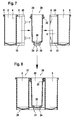
- FIG. 7 shows the individual containers from which the proposed invention Reagent cassette is added, refer to.
- the respective cassette parts 2, 3 and the container 20 shown in section are in Direction of the arrows joined together.
- Container forming cassette parts 2, 3 snap the locking lugs 7 of a container forming Cassette part 2 in the latching openings 6 of the other, forming a container Cassette part 3 a.
- the container 20 Beadflasche
- Inclusion of a particle-containing reagent so between the to be joined Cassette parts 2, 3 aligned that the positioning ring 22 below the bezels 29th at the top of the two cassette parts 2 comes to rest.
- the cassette parts 2 and 3 and the Container 20 can be a filling of reagents and a Consequently, cassette assembly takes place independently of one another in terms of time. How out the illustrations according to the figures 7 and 8, a joining follows the According to the invention proposed reagent cartridge 1 by simply plugging together the components 2, 3 and 20, without any additional accessories such as lids or neck-shaped joining elements would be required.
- a coupling piece can be removed, with which the slotted ring at the bottom of the container containing the particle-containing reagent is added.
- the coupling piece 31 shown in Figure 9 has a disc-shaped Base 32 and a trained on this coupling head 33.
- the slotted Ring i. the resiliently formed tabs 34 on the coupling head 33 a.
- the springy trained, separated by slots tabs 34 enclose the Coupling head 33 in its entirety.
- Through the slotted ring 21, formed on the in Rotation to be offset container 20 for receiving a particle-containing reagent, and the coupling piece 31 is a coupling connection produced by which a Rotation into the particle-containing reagent receiving container 20 (Beadflasche) can be initiated.
- the engagement of the resiliently formed tabs 34 of the Slotted ring 21 further assists in proper positioning of the container 20 within the reagent cartridge 1 and is advantageous for a low-friction bottle rotation within the reagent cartridge 1 in the assembled state 26.
- the engagement of the slotted ring 21 on the coupling piece 31 takes place at manual or automatic Equipping a reagent magazine, as will be described below.
- Locking connection between the latching openings 6 and the locking lugs 7 to each other can also be configured so that filling container forming cassette parts 2, 3 a non-destructive release of the two cassette parts from each other is not possible.
- a reagent magazine is shown in a schematic view out.
- the reagent magazine 40 essentially comprises a magazine plate 41 which is separated from a central shaft 46 is held.
- the magazine plate 41 rotates in the direction of rotation 42, indicated by the arrow identified by reference numeral 42.
- the Reagent magazine 40 may also be formed in a matrix arrangement.
- the magazine plate 41 are several coupling pieces 31 inserted.
- the coupling pieces 31 are in turn of a drive shaft 45 driven via a gear 44 with a drive 43 in Connection stands.
- reagent cartridges 1 are in pre-assembled state 26 positioned. Because of the newly trained Underside 28 of the reagent cartridges 1 in the assembled state 26 are this plan on the top of the magazine plate 41 on.
- the reagent cassettes 1 in the ready-made Condition 26 are positioned on the top of the magazine plate 41 that the slotted ring of a container 20 of a reagent cartridge 1 in the assembled state 26, the driven coupling pieces 31 engages around the magazine plate 41. This will a coupling connection between the rotatable in the reagent cartridge 1 in ready-made state 26 stored container 20 for receiving a particle-containing Reagent created.
- the gear 44 and the drive shaft 45th of the coupling piece 31 is rotatably mounted in the reagent cartridge 1 container 20th rotated to receive a particle-containing reagent, while the Reagent cassette 1 in the assembled state 26 in its position at the top of the Magazine plate 41 remains.
- a reagent cartridge 1 three reagents be included, of which the homogenized, since sedimenting particles containing reagent in the via the coupling connection 21, 31 driven container 20 (bead bottle) is included. In one operation can therefore be pro Reagent cassette 1 prepare several reagents for further processing. From the Representation according to Figure 10 shows that at the top of the magazine plate 41st according to the number of driven coupling pieces 31 more Reagent Cassettes 1 can be treated in parallel.
- the containers forming Cassette parts 2, 3 are respectively on the snap fasteners 6, 7, latching openings 6 and Locking lugs 7 comprising, releasably connected to each other, wherein the clip connection between the cassette parts 2, 3 forming the containers can also be designed that a non-destructive loosening is no longer possible.
- FIG. 11 shows reagent cartridges which are the first Container forming cassette part 2 (R1 bottle) and the second container forming Have cassette part 3.
- the cassette parts 2 and 3 are by a Locking connection, given by the latching opening 6 and the locking lug 7 latching therein connected with each other.
- the Reagent cassettes are closed at the top and contain individual containers 20 (Beadflaschen).
- the Beadflaschen 20 are secured by means of positioning rings 22 and coupled in the region of the bottle bottom 30 with the coupling piece 31.
- the Coupling piece 31 in turn is driven by a drive shaft 52, which with a Pulley or the like is provided and for example by a toothed belt 51st can be driven.
- the toothed belt 51 encloses another drive wheel, which is the reagent cartridge shown in Figure 11 on the left side of the figure, consisting of the first container forming cassette part 2 and the second container forming cassette part 3 is arranged.
- the timing belt 51 is about a Drive gear 50 of a drive 49 driven and offset by means of drive shafts 52, the coupling pieces 31, which at the bottom in the region of the bottle bottom 30 through the coupling piece 31 coupled container 20 (Beadflaschen) within the Reagent Cassettes in rotation.
- reagent cassette three reagents may be included in different containers 20 (bead bottles), from which the middle of the coupling piece 31, the drive shaft 52, the toothed belt 51st and the drive 49 containing reagent to be homogenized container bottle 20 in Rotation is offset.
- This can be similar in one operation as in the in FIG 10 illustrated embodiment per reagent cartridge 1 several reagents for a Prepare further processing.
- the sedimenting particles to be homogenized containing reagent is preferably in the via the coupling connection 31, 52nd driven container 20 (bead bottle) was added.
Landscapes
- Chemical & Material Sciences (AREA)
- Chemical Kinetics & Catalysis (AREA)
- Health & Medical Sciences (AREA)
- Dispersion Chemistry (AREA)
- Analytical Chemistry (AREA)
- General Health & Medical Sciences (AREA)
- Hematology (AREA)
- Clinical Laboratory Science (AREA)
- Automatic Analysis And Handling Materials Therefor (AREA)
- Stackable Containers (AREA)
- Investigating Or Analysing Biological Materials (AREA)
Applications Claiming Priority (2)
| Application Number | Priority Date | Filing Date | Title |
|---|---|---|---|
| DE10360526 | 2003-12-22 | ||
| DE10360526A DE10360526A1 (de) | 2003-12-22 | 2003-12-22 | Reagenzkassette mit Reagenzbehälter für partikelhaltiges Reagenz für dessen noninvasive Homogenisierung |
Publications (3)
| Publication Number | Publication Date |
|---|---|
| EP1550498A2 true EP1550498A2 (fr) | 2005-07-06 |
| EP1550498A3 EP1550498A3 (fr) | 2005-11-30 |
| EP1550498B1 EP1550498B1 (fr) | 2008-07-30 |
Family
ID=34559770
Family Applications (1)
| Application Number | Title | Priority Date | Filing Date |
|---|---|---|---|
| EP04029815A Not-in-force EP1550498B1 (fr) | 2003-12-22 | 2004-12-16 | Cartouche de réactifs avec des récipients pour réactifs contenant des particules pour leur homegénéisation non invasive |
Country Status (7)
| Country | Link |
|---|---|
| US (1) | US7790108B2 (fr) |
| EP (1) | EP1550498B1 (fr) |
| JP (1) | JP4106050B2 (fr) |
| AT (1) | ATE402755T1 (fr) |
| CA (1) | CA2490085C (fr) |
| DE (2) | DE10360526A1 (fr) |
| ES (1) | ES2311776T3 (fr) |
Cited By (1)
| Publication number | Priority date | Publication date | Assignee | Title |
|---|---|---|---|---|
| US9632103B2 (en) | 2013-03-15 | 2017-04-25 | Abbott Laboraties | Linear track diagnostic analyzer |
Families Citing this family (18)
| Publication number | Priority date | Publication date | Assignee | Title |
|---|---|---|---|---|
| JP4787026B2 (ja) * | 2006-01-20 | 2011-10-05 | 凸版印刷株式会社 | 反応容器 |
| FR2904114B1 (fr) * | 2006-07-21 | 2008-10-17 | Biocode Hycel France Sa Sa | Cartouche pour produits reactifs destinee a etre utilisee da dans des apprareils d'analyse, portoir destine a recevoir cette cartouche, et ensemble d'analyse comprenant cette cartouche et ce portoir |
| US7731414B2 (en) * | 2007-02-08 | 2010-06-08 | Instrumentation Laboratory Company | Reagent cartridge mixing tube |
| WO2009090989A1 (fr) * | 2008-01-15 | 2009-07-23 | Kyowa Medex Co., Ltd. | Récipient à réactif |
| US20100159498A1 (en) * | 2008-12-19 | 2010-06-24 | Ritzen Kalle | Blood analyzer with a blood cell sedimentation control mechanism and method of use |
| JP2010202269A (ja) * | 2009-03-05 | 2010-09-16 | Beckman Coulter Inc | 反応カード製造装置 |
| WO2014002952A1 (fr) * | 2012-06-25 | 2014-01-03 | 協和メデックス株式会社 | Cassette et ensemble de réactifs |
| USD978375S1 (en) | 2013-03-13 | 2023-02-14 | Abbott Laboratories | Reagent container |
| US9535082B2 (en) * | 2013-03-13 | 2017-01-03 | Abbott Laboratories | Methods and apparatus to agitate a liquid |
| USD962471S1 (en) | 2013-03-13 | 2022-08-30 | Abbott Laboratories | Reagent container |
| US10058866B2 (en) | 2013-03-13 | 2018-08-28 | Abbott Laboratories | Methods and apparatus to mitigate bubble formation in a liquid |
| US9513303B2 (en) | 2013-03-15 | 2016-12-06 | Abbott Laboratories | Light-blocking system for a diagnostic analyzer |
| EP2972219B1 (fr) | 2013-03-15 | 2022-01-19 | Abbott Laboratories | Gestionnaire de réactif automatisé de système analyseur de diagnostic |
| US9897622B2 (en) | 2013-04-22 | 2018-02-20 | Hitachi High-Technologies Corporation | Automatic analyzer |
| US9724657B2 (en) * | 2013-10-22 | 2017-08-08 | Tyme, Inc. | High-speed centrifugal mixing devices and methods of use |
| USD848636S1 (en) | 2015-10-20 | 2019-05-14 | Roche Diagnostics Operations, Inc. | Reagent container |
| CN111812320B (zh) * | 2020-07-28 | 2023-04-25 | 山东圣剑医学研究有限公司 | 一种全自动免疫分析装置的检测试剂盒 |
| CN112973520A (zh) * | 2021-02-07 | 2021-06-18 | 浙江交投丽新矿业有限公司 | 一种用于矿山生态修复的复绿设备 |
Citations (4)
| Publication number | Priority date | Publication date | Assignee | Title |
|---|---|---|---|---|
| EP0651254A1 (fr) * | 1993-10-28 | 1995-05-03 | F. Hoffmann-La Roche Ag | Nécessaire à réactifs et analyseur l'utilisant |
| JPH10151125A (ja) * | 1996-11-21 | 1998-06-09 | Corp Miyuki:Kk | Dnaによる人物識別システム |
| EP0937983A1 (fr) * | 1992-04-09 | 1999-08-25 | F. Hoffmann-La Roche Ag | Analyseur automatique |
| US6149872A (en) * | 1995-11-02 | 2000-11-21 | Byk-Sangtec Diagnostica Gmbh & Co. Kg | Modular reagent cartridge |
Family Cites Families (17)
| Publication number | Priority date | Publication date | Assignee | Title |
|---|---|---|---|---|
| US3415361A (en) * | 1966-12-22 | 1968-12-10 | Miles Lab | Test device and container therefor |
| US2413094A (en) * | 1944-12-09 | 1946-12-24 | Remington Arms Co Inc | Metal treating apparatus |
| CH444126A (de) * | 1965-09-08 | 1967-09-30 | Inventa Ag | Vorrichtung zur kontinuierlichen Durchführung von chemischen Reaktionen in viskosen Flüssigkeiten |
| ES2062981T3 (es) * | 1986-07-11 | 1995-01-01 | Beckman Instruments Inc | Cartucho de reactivo. |
| JPS6415125A (en) * | 1987-07-07 | 1989-01-19 | Sanko Air Plant | Mixer for particulate matter |
| US5183638A (en) * | 1989-12-04 | 1993-02-02 | Kabushiki Kaisha Nittec | Automatic immunity analysis apparatus with magnetic particle separation |
| ES2106023T3 (es) * | 1989-12-22 | 1997-11-01 | Alfa Biotech Spa | Aparato para la agitacion selectiva de componentes de reaccion. |
| GB9020352D0 (en) * | 1990-09-18 | 1990-10-31 | Anagen Ltd | Assay or reaction apparatus |
| US5380487A (en) * | 1992-05-05 | 1995-01-10 | Pasteur Sanofi Diagnostics | Device for automatic chemical analysis |
| US5428997A (en) | 1992-07-20 | 1995-07-04 | Pasteur Sanofi Diagnostics | Method of and device for fluid surface detection using an ultrasonic transducer |
| US5772962A (en) * | 1995-05-29 | 1998-06-30 | Hitachi, Ltd. | Analyzing apparatus using disposable reaction vessels |
| US5637962A (en) * | 1995-06-09 | 1997-06-10 | The Regents Of The University Of California Office Of Technology Transfer | Plasma wake field XUV radiation source |
| US5609822A (en) * | 1995-07-07 | 1997-03-11 | Ciba Corning Diagnostics Corp. | Reagent handling system and reagent pack for use therein |
| WO1997041445A1 (fr) * | 1996-04-26 | 1997-11-06 | Dade International Inc. | Procede et appareil pour pretraiter des echantillons dans un analyseur chimique automatique |
| US5856194A (en) * | 1996-09-19 | 1999-01-05 | Abbott Laboratories | Method for determination of item of interest in a sample |
| US5795784A (en) * | 1996-09-19 | 1998-08-18 | Abbott Laboratories | Method of performing a process for determining an item of interest in a sample |
| RU2191630C1 (ru) * | 2001-06-09 | 2002-10-27 | Общество с ограниченной ответственностью "Кварц Т-2000" | Низкочастотный акустический преобразователь |
-
2003
- 2003-12-22 DE DE10360526A patent/DE10360526A1/de not_active Withdrawn
-
2004
- 2004-12-13 CA CA2490085A patent/CA2490085C/fr not_active Expired - Fee Related
- 2004-12-16 AT AT04029815T patent/ATE402755T1/de active
- 2004-12-16 DE DE502004007729T patent/DE502004007729D1/de active Active
- 2004-12-16 ES ES04029815T patent/ES2311776T3/es active Active
- 2004-12-16 EP EP04029815A patent/EP1550498B1/fr not_active Not-in-force
- 2004-12-21 JP JP2004369506A patent/JP4106050B2/ja not_active Expired - Fee Related
- 2004-12-22 US US11/021,071 patent/US7790108B2/en not_active Expired - Fee Related
Patent Citations (4)
| Publication number | Priority date | Publication date | Assignee | Title |
|---|---|---|---|---|
| EP0937983A1 (fr) * | 1992-04-09 | 1999-08-25 | F. Hoffmann-La Roche Ag | Analyseur automatique |
| EP0651254A1 (fr) * | 1993-10-28 | 1995-05-03 | F. Hoffmann-La Roche Ag | Nécessaire à réactifs et analyseur l'utilisant |
| US6149872A (en) * | 1995-11-02 | 2000-11-21 | Byk-Sangtec Diagnostica Gmbh & Co. Kg | Modular reagent cartridge |
| JPH10151125A (ja) * | 1996-11-21 | 1998-06-09 | Corp Miyuki:Kk | Dnaによる人物識別システム |
Cited By (1)
| Publication number | Priority date | Publication date | Assignee | Title |
|---|---|---|---|---|
| US9632103B2 (en) | 2013-03-15 | 2017-04-25 | Abbott Laboraties | Linear track diagnostic analyzer |
Also Published As
| Publication number | Publication date |
|---|---|
| JP4106050B2 (ja) | 2008-06-25 |
| DE502004007729D1 (de) | 2008-09-11 |
| JP2005181338A (ja) | 2005-07-07 |
| ES2311776T3 (es) | 2009-02-16 |
| DE10360526A1 (de) | 2005-07-14 |
| EP1550498B1 (fr) | 2008-07-30 |
| CA2490085C (fr) | 2011-02-15 |
| ATE402755T1 (de) | 2008-08-15 |
| US7790108B2 (en) | 2010-09-07 |
| US20050153426A1 (en) | 2005-07-14 |
| EP1550498A3 (fr) | 2005-11-30 |
| CA2490085A1 (fr) | 2005-06-22 |
Similar Documents
| Publication | Publication Date | Title |
|---|---|---|
| EP1550498B1 (fr) | Cartouche de réactifs avec des récipients pour réactifs contenant des particules pour leur homegénéisation non invasive | |
| EP0871894B1 (fr) | Cartouche modulaire de reactifs | |
| DE60030310T2 (de) | Mix- und giessapparat mit drehbarem arm und zugehörigem gefäss | |
| EP1344500B1 (fr) | Capsule de mélange de plusieurs composants, en particulier pour l'art dentaire | |
| EP1940539B1 (fr) | Contenant jetable a agitateur | |
| DE60100697T2 (de) | Auswechselbare, konforme auskleidung für zentrifugenbehälter | |
| CH662982A5 (de) | Reibgeschweisster behaelter. | |
| EP2514515B1 (fr) | Procédé de mélange d'un premier et d'un deuxième composant | |
| DE102009030305A1 (de) | Rührvorrichtung mit zusammenfaltbarem Rührflügel | |
| EP1474235A1 (fr) | Dispositif de preparation d'echantillons et appareillage d'essai faisant appel a ce dernier | |
| DE19735539A1 (de) | Vorrichtung zum Rühren bzw. Herstellung von Mischungen o. dgl. in einem Rührgefäß sowie Flügelrührer | |
| DE19819447A1 (de) | Vorrichtung und Verfahren zum Mischen und Waschen von Flüssigkeiten und/oder Feststoffen | |
| DE102006022651B3 (de) | Behälter mit flexiblen Wänden | |
| EP2371343B1 (fr) | Dispositif de stockage et de dosage d'un solvant | |
| WO2005002729A1 (fr) | Utilisation d'un contenant a usage unique, dispositif microfluidique et procede de traitement de molecules | |
| DE60203487T2 (de) | Flexibler behälter und verfahren zu seiner herstellung | |
| DE4428664C2 (de) | Behälter, Anordnung und Verfahren zur Herstellung ,Aufbewahrung und Abgabe einer Individualrezeptur | |
| DE2659627B2 (de) | Vorrichtung zur Trennung chemischer Substanzen unter Erzeugung von Sterillösungen | |
| EP3490699B1 (fr) | Agitateur modulaire | |
| DE19900347A1 (de) | Vorrichtung zum Pipettieren und Mischen | |
| EP2559633A1 (fr) | Couvercle de seau avec compartiment intégré | |
| DE102015011881B4 (de) | Mischsystem und Verfahren zum Mischen eines Fluids und/oder eines Feststoffs | |
| EP3560582A1 (fr) | Récipient à chambres multiples destiné au conditionnement et au mélange d'un système adhésif ou de revêtement liquide multicomposant | |
| DE202023104513U1 (de) | Behälter für ein Trockenkonzentrat | |
| DE202022106955U1 (de) | Mischbehälter mit Rührwerk für automatische Küchenmaschine |
Legal Events
| Date | Code | Title | Description |
|---|---|---|---|
| PUAI | Public reference made under article 153(3) epc to a published international application that has entered the european phase |
Free format text: ORIGINAL CODE: 0009012 |
|
| AK | Designated contracting states |
Kind code of ref document: A2 Designated state(s): AT BE BG CH CY CZ DE DK EE ES FI FR GB GR HU IE IS IT LI LT LU MC NL PL PT RO SE SI SK TR |
|
| AX | Request for extension of the european patent |
Extension state: AL BA HR LV MK YU |
|
| PUAL | Search report despatched |
Free format text: ORIGINAL CODE: 0009013 |
|
| AK | Designated contracting states |
Kind code of ref document: A3 Designated state(s): AT BE BG CH CY CZ DE DK EE ES FI FR GB GR HU IE IS IT LI LT LU MC NL PL PT RO SE SI SK TR |
|
| AX | Request for extension of the european patent |
Extension state: AL BA HR LV MK YU |
|
| RIC1 | Information provided on ipc code assigned before grant |
Ipc: 7B 65D 21/02 B Ipc: 7B 01F 15/00 B Ipc: 7B 01L 3/00 B Ipc: 7B 01F 9/00 B Ipc: 7B 01F 3/12 A |
|
| 17P | Request for examination filed |
Effective date: 20060112 |
|
| AKX | Designation fees paid |
Designated state(s): AT BE BG CH CY CZ DE DK EE ES FI FR GB GR HU IE IS IT LI LT LU MC NL PL PT RO SE SI SK TR |
|
| 17Q | First examination report despatched |
Effective date: 20060328 |
|
| GRAP | Despatch of communication of intention to grant a patent |
Free format text: ORIGINAL CODE: EPIDOSNIGR1 |
|
| RAP1 | Party data changed (applicant data changed or rights of an application transferred) |
Owner name: F. HOFFMANN-LA ROCHE AG Owner name: ROCHE DIAGNOSTICS GMBH |
|
| GRAS | Grant fee paid |
Free format text: ORIGINAL CODE: EPIDOSNIGR3 |
|
| GRAA | (expected) grant |
Free format text: ORIGINAL CODE: 0009210 |
|
| AK | Designated contracting states |
Kind code of ref document: B1 Designated state(s): AT BE BG CH CY CZ DE DK EE ES FI FR GB GR HU IE IS IT LI LT LU MC NL PL PT RO SE SI SK TR |
|
| REG | Reference to a national code |
Ref country code: GB Ref legal event code: FG4D Free format text: NOT ENGLISH |
|
| REG | Reference to a national code |
Ref country code: CH Ref legal event code: EP |
|
| REG | Reference to a national code |
Ref country code: CH Ref legal event code: NV Representative=s name: BOHEST AG |
|
| REF | Corresponds to: |
Ref document number: 502004007729 Country of ref document: DE Date of ref document: 20080911 Kind code of ref document: P |
|
| REG | Reference to a national code |
Ref country code: IE Ref legal event code: FG4D Free format text: LANGUAGE OF EP DOCUMENT: GERMAN |
|
| PG25 | Lapsed in a contracting state [announced via postgrant information from national office to epo] |
Ref country code: LT Free format text: LAPSE BECAUSE OF FAILURE TO SUBMIT A TRANSLATION OF THE DESCRIPTION OR TO PAY THE FEE WITHIN THE PRESCRIBED TIME-LIMIT Effective date: 20080730 Ref country code: IS Free format text: LAPSE BECAUSE OF FAILURE TO SUBMIT A TRANSLATION OF THE DESCRIPTION OR TO PAY THE FEE WITHIN THE PRESCRIBED TIME-LIMIT Effective date: 20081130 Ref country code: PT Free format text: LAPSE BECAUSE OF FAILURE TO SUBMIT A TRANSLATION OF THE DESCRIPTION OR TO PAY THE FEE WITHIN THE PRESCRIBED TIME-LIMIT Effective date: 20081230 Ref country code: NL Free format text: LAPSE BECAUSE OF FAILURE TO SUBMIT A TRANSLATION OF THE DESCRIPTION OR TO PAY THE FEE WITHIN THE PRESCRIBED TIME-LIMIT Effective date: 20080730 |
|
| REG | Reference to a national code |
Ref country code: ES Ref legal event code: FG2A Ref document number: 2311776 Country of ref document: ES Kind code of ref document: T3 |
|
| PG25 | Lapsed in a contracting state [announced via postgrant information from national office to epo] |
Ref country code: BG Free format text: LAPSE BECAUSE OF FAILURE TO SUBMIT A TRANSLATION OF THE DESCRIPTION OR TO PAY THE FEE WITHIN THE PRESCRIBED TIME-LIMIT Effective date: 20081030 Ref country code: SI Free format text: LAPSE BECAUSE OF FAILURE TO SUBMIT A TRANSLATION OF THE DESCRIPTION OR TO PAY THE FEE WITHIN THE PRESCRIBED TIME-LIMIT Effective date: 20080730 Ref country code: FI Free format text: LAPSE BECAUSE OF FAILURE TO SUBMIT A TRANSLATION OF THE DESCRIPTION OR TO PAY THE FEE WITHIN THE PRESCRIBED TIME-LIMIT Effective date: 20080730 |
|
| REG | Reference to a national code |
Ref country code: IE Ref legal event code: FD4D |
|
| PG25 | Lapsed in a contracting state [announced via postgrant information from national office to epo] |
Ref country code: EE Free format text: LAPSE BECAUSE OF FAILURE TO SUBMIT A TRANSLATION OF THE DESCRIPTION OR TO PAY THE FEE WITHIN THE PRESCRIBED TIME-LIMIT Effective date: 20080730 Ref country code: IE Free format text: LAPSE BECAUSE OF FAILURE TO SUBMIT A TRANSLATION OF THE DESCRIPTION OR TO PAY THE FEE WITHIN THE PRESCRIBED TIME-LIMIT Effective date: 20080730 Ref country code: DK Free format text: LAPSE BECAUSE OF FAILURE TO SUBMIT A TRANSLATION OF THE DESCRIPTION OR TO PAY THE FEE WITHIN THE PRESCRIBED TIME-LIMIT Effective date: 20080730 |
|
| PG25 | Lapsed in a contracting state [announced via postgrant information from national office to epo] |
Ref country code: CZ Free format text: LAPSE BECAUSE OF FAILURE TO SUBMIT A TRANSLATION OF THE DESCRIPTION OR TO PAY THE FEE WITHIN THE PRESCRIBED TIME-LIMIT Effective date: 20080730 Ref country code: SK Free format text: LAPSE BECAUSE OF FAILURE TO SUBMIT A TRANSLATION OF THE DESCRIPTION OR TO PAY THE FEE WITHIN THE PRESCRIBED TIME-LIMIT Effective date: 20080730 Ref country code: RO Free format text: LAPSE BECAUSE OF FAILURE TO SUBMIT A TRANSLATION OF THE DESCRIPTION OR TO PAY THE FEE WITHIN THE PRESCRIBED TIME-LIMIT Effective date: 20080730 |
|
| PLBE | No opposition filed within time limit |
Free format text: ORIGINAL CODE: 0009261 |
|
| STAA | Information on the status of an ep patent application or granted ep patent |
Free format text: STATUS: NO OPPOSITION FILED WITHIN TIME LIMIT |
|
| BERE | Be: lapsed |
Owner name: F. HOFFMANN-LA ROCHE A.G. Effective date: 20081231 Owner name: ROCHE DIAGNOSTICS G.M.B.H. Effective date: 20081231 |
|
| 26N | No opposition filed |
Effective date: 20090506 |
|
| PG25 | Lapsed in a contracting state [announced via postgrant information from national office to epo] |
Ref country code: MC Free format text: LAPSE BECAUSE OF NON-PAYMENT OF DUE FEES Effective date: 20081231 |
|
| PG25 | Lapsed in a contracting state [announced via postgrant information from national office to epo] |
Ref country code: BE Free format text: LAPSE BECAUSE OF NON-PAYMENT OF DUE FEES Effective date: 20081231 |
|
| PG25 | Lapsed in a contracting state [announced via postgrant information from national office to epo] |
Ref country code: SE Free format text: LAPSE BECAUSE OF FAILURE TO SUBMIT A TRANSLATION OF THE DESCRIPTION OR TO PAY THE FEE WITHIN THE PRESCRIBED TIME-LIMIT Effective date: 20081030 |
|
| PG25 | Lapsed in a contracting state [announced via postgrant information from national office to epo] |
Ref country code: PL Free format text: LAPSE BECAUSE OF FAILURE TO SUBMIT A TRANSLATION OF THE DESCRIPTION OR TO PAY THE FEE WITHIN THE PRESCRIBED TIME-LIMIT Effective date: 20080730 |
|
| PG25 | Lapsed in a contracting state [announced via postgrant information from national office to epo] |
Ref country code: HU Free format text: LAPSE BECAUSE OF FAILURE TO SUBMIT A TRANSLATION OF THE DESCRIPTION OR TO PAY THE FEE WITHIN THE PRESCRIBED TIME-LIMIT Effective date: 20090131 Ref country code: CY Free format text: LAPSE BECAUSE OF FAILURE TO SUBMIT A TRANSLATION OF THE DESCRIPTION OR TO PAY THE FEE WITHIN THE PRESCRIBED TIME-LIMIT Effective date: 20080730 Ref country code: LU Free format text: LAPSE BECAUSE OF NON-PAYMENT OF DUE FEES Effective date: 20081216 |
|
| PG25 | Lapsed in a contracting state [announced via postgrant information from national office to epo] |
Ref country code: TR Free format text: LAPSE BECAUSE OF FAILURE TO SUBMIT A TRANSLATION OF THE DESCRIPTION OR TO PAY THE FEE WITHIN THE PRESCRIBED TIME-LIMIT Effective date: 20080730 |
|
| PG25 | Lapsed in a contracting state [announced via postgrant information from national office to epo] |
Ref country code: GR Free format text: LAPSE BECAUSE OF FAILURE TO SUBMIT A TRANSLATION OF THE DESCRIPTION OR TO PAY THE FEE WITHIN THE PRESCRIBED TIME-LIMIT Effective date: 20081031 |
|
| PGFP | Annual fee paid to national office [announced via postgrant information from national office to epo] |
Ref country code: GB Payment date: 20131126 Year of fee payment: 10 Ref country code: AT Payment date: 20131126 Year of fee payment: 10 Ref country code: CH Payment date: 20131029 Year of fee payment: 10 |
|
| PGFP | Annual fee paid to national office [announced via postgrant information from national office to epo] |
Ref country code: ES Payment date: 20131211 Year of fee payment: 10 Ref country code: FR Payment date: 20131126 Year of fee payment: 10 Ref country code: IT Payment date: 20131217 Year of fee payment: 10 |
|
| PGFP | Annual fee paid to national office [announced via postgrant information from national office to epo] |
Ref country code: DE Payment date: 20131230 Year of fee payment: 10 |
|
| REG | Reference to a national code |
Ref country code: CH Ref legal event code: PCAR Free format text: NEW ADDRESS: HOLBEINSTRASSE 36-38, 4051 BASEL (CH) |
|
| REG | Reference to a national code |
Ref country code: DE Ref legal event code: R119 Ref document number: 502004007729 Country of ref document: DE |
|
| REG | Reference to a national code |
Ref country code: CH Ref legal event code: PL |
|
| REG | Reference to a national code |
Ref country code: AT Ref legal event code: MM01 Ref document number: 402755 Country of ref document: AT Kind code of ref document: T Effective date: 20141216 |
|
| GBPC | Gb: european patent ceased through non-payment of renewal fee |
Effective date: 20141216 |
|
| REG | Reference to a national code |
Ref country code: FR Ref legal event code: ST Effective date: 20150831 |
|
| PG25 | Lapsed in a contracting state [announced via postgrant information from national office to epo] |
Ref country code: DE Free format text: LAPSE BECAUSE OF NON-PAYMENT OF DUE FEES Effective date: 20150701 Ref country code: GB Free format text: LAPSE BECAUSE OF NON-PAYMENT OF DUE FEES Effective date: 20141216 Ref country code: LI Free format text: LAPSE BECAUSE OF NON-PAYMENT OF DUE FEES Effective date: 20141231 Ref country code: CH Free format text: LAPSE BECAUSE OF NON-PAYMENT OF DUE FEES Effective date: 20141231 |
|
| PG25 | Lapsed in a contracting state [announced via postgrant information from national office to epo] |
Ref country code: AT Free format text: LAPSE BECAUSE OF NON-PAYMENT OF DUE FEES Effective date: 20141216 Ref country code: FR Free format text: LAPSE BECAUSE OF NON-PAYMENT OF DUE FEES Effective date: 20141231 |
|
| PG25 | Lapsed in a contracting state [announced via postgrant information from national office to epo] |
Ref country code: IT Free format text: LAPSE BECAUSE OF NON-PAYMENT OF DUE FEES Effective date: 20141216 |
|
| REG | Reference to a national code |
Ref country code: ES Ref legal event code: FD2A Effective date: 20160127 |
|
| PG25 | Lapsed in a contracting state [announced via postgrant information from national office to epo] |
Ref country code: ES Free format text: LAPSE BECAUSE OF NON-PAYMENT OF DUE FEES Effective date: 20141217 |