EP1550498A2 - Reagent cartridge with reagent containers for reagents containing particles for their non-invasive homogenization - Google Patents
Reagent cartridge with reagent containers for reagents containing particles for their non-invasive homogenization Download PDFInfo
- Publication number
- EP1550498A2 EP1550498A2 EP04029815A EP04029815A EP1550498A2 EP 1550498 A2 EP1550498 A2 EP 1550498A2 EP 04029815 A EP04029815 A EP 04029815A EP 04029815 A EP04029815 A EP 04029815A EP 1550498 A2 EP1550498 A2 EP 1550498A2
- Authority
- EP
- European Patent Office
- Prior art keywords
- cassette
- container
- reagent
- particle
- containers
- Prior art date
- Legal status (The legal status is an assumption and is not a legal conclusion. Google has not performed a legal analysis and makes no representation as to the accuracy of the status listed.)
- Granted
Links
Images


Classifications
-
- B—PERFORMING OPERATIONS; TRANSPORTING
- B01—PHYSICAL OR CHEMICAL PROCESSES OR APPARATUS IN GENERAL
- B01L—CHEMICAL OR PHYSICAL LABORATORY APPARATUS FOR GENERAL USE
- B01L3/00—Containers or dishes for laboratory use, e.g. laboratory glassware; Droppers
- B01L3/50—Containers for the purpose of retaining a material to be analysed, e.g. test tubes
- B01L3/508—Containers for the purpose of retaining a material to be analysed, e.g. test tubes rigid containers not provided for above
-
- B—PERFORMING OPERATIONS; TRANSPORTING
- B01—PHYSICAL OR CHEMICAL PROCESSES OR APPARATUS IN GENERAL
- B01F—MIXING, e.g. DISSOLVING, EMULSIFYING OR DISPERSING
- B01F29/00—Mixers with rotating receptacles
- B01F29/30—Mixing the contents of individual packages or containers, e.g. by rotating tins or bottles
- B01F29/32—Containers specially adapted for coupling to rotating frames or the like; Coupling means therefor
- B01F29/322—Containers specially adapted for coupling to rotating frames or the like; Coupling means therefor of two or more containers supported for simultaneous mixing, e.g. for bottles in crates
-
- B—PERFORMING OPERATIONS; TRANSPORTING
- B01—PHYSICAL OR CHEMICAL PROCESSES OR APPARATUS IN GENERAL
- B01F—MIXING, e.g. DISSOLVING, EMULSIFYING OR DISPERSING
- B01F23/00—Mixing according to the phases to be mixed, e.g. dispersing or emulsifying
- B01F23/02—Maintaining the aggregation state of the mixed materials
- B01F23/023—Preventing sedimentation, conglomeration or agglomeration of solid ingredients during or after mixing by maintaining mixed ingredients in movement
-
- B—PERFORMING OPERATIONS; TRANSPORTING
- B01—PHYSICAL OR CHEMICAL PROCESSES OR APPARATUS IN GENERAL
- B01F—MIXING, e.g. DISSOLVING, EMULSIFYING OR DISPERSING
- B01F23/00—Mixing according to the phases to be mixed, e.g. dispersing or emulsifying
- B01F23/50—Mixing liquids with solids
- B01F23/53—Mixing liquids with solids using driven stirrers
-
- B—PERFORMING OPERATIONS; TRANSPORTING
- B01—PHYSICAL OR CHEMICAL PROCESSES OR APPARATUS IN GENERAL
- B01F—MIXING, e.g. DISSOLVING, EMULSIFYING OR DISPERSING
- B01F29/00—Mixers with rotating receptacles
- B01F29/10—Mixers with rotating receptacles with receptacles rotated about two different axes, e.g. receptacles having planetary motion
-
- B—PERFORMING OPERATIONS; TRANSPORTING
- B01—PHYSICAL OR CHEMICAL PROCESSES OR APPARATUS IN GENERAL
- B01F—MIXING, e.g. DISSOLVING, EMULSIFYING OR DISPERSING
- B01F35/00—Accessories for mixers; Auxiliary operations or auxiliary devices; Parts or details of general application
- B01F35/50—Mixing receptacles
-
- B—PERFORMING OPERATIONS; TRANSPORTING
- B01—PHYSICAL OR CHEMICAL PROCESSES OR APPARATUS IN GENERAL
- B01F—MIXING, e.g. DISSOLVING, EMULSIFYING OR DISPERSING
- B01F35/00—Accessories for mixers; Auxiliary operations or auxiliary devices; Parts or details of general application
- B01F35/56—General build-up of the mixers
- B01F35/561—General build-up of the mixers the mixer being built-up from a plurality of modules or stacked plates comprising complete or partial elements of the mixer
-
- G—PHYSICS
- G01—MEASURING; TESTING
- G01N—INVESTIGATING OR ANALYSING MATERIALS BY DETERMINING THEIR CHEMICAL OR PHYSICAL PROPERTIES
- G01N35/00—Automatic analysis not limited to methods or materials provided for in any single one of groups G01N1/00 - G01N33/00; Handling materials therefor
- G01N2035/00465—Separating and mixing arrangements
- G01N2035/00524—Mixing by agitating sample carrier
Landscapes
- Chemical & Material Sciences (AREA)
- Chemical Kinetics & Catalysis (AREA)
- Health & Medical Sciences (AREA)
- Analytical Chemistry (AREA)
- General Health & Medical Sciences (AREA)
- Hematology (AREA)
- Clinical Laboratory Science (AREA)
- Dispersion Chemistry (AREA)
- Automatic Analysis And Handling Materials Therefor (AREA)
- Investigating Or Analysing Biological Materials (AREA)
- Stackable Containers (AREA)
Abstract
Description
Die Erfindung bezieht sich auf eine Reagenzkassette mit einem Reagenzbehälter für ein partikelhaltiges Reagenz, welche insbesondere geeignet ist zur noninvasiven Homogenisierung von beschichteten und sedimentierenden Partikeln sowie ein Magazin.The invention relates to a reagent cartridge with a reagent container for a particle-containing reagent, which is particularly suitable for noninvasive Homogenization of coated and sedimenting particles as well as a magazine.
Diagnostische Assay-Systeme beinhalten in vielen Fällen die Verwendung von Partikeln in einer Flüssigkeit für den Ablauf von Reaktionen. Dabei handelt es sich um Verfahren zum Nachweis chemischer Bindungsreaktionen, zum Beispiel im Zusammenhang mit Antigenen oder Antikörpern. Für die korrekte Bearbeitung von Assays auf diesen Systemen ist es in der Regel erforderlich, dass die Partikel in den zugehörigen Behältern zum Zeitpunkt der Entnahme eine möglichst homogene Verteilung aufweisen. Eine homogene Partikelverteilung vermeidet zum Beispiel durch Sedimentationsprozesse auftretende Konzentrationsunterschiede zwischen aufeinanderfolgenden Entnahmen aus den Behältern.Diagnostic assay systems often involve the use of particles in a liquid for the course of reactions. These are procedures for Detection of chemical binding reactions, for example in connection with Antigens or antibodies. For the correct processing of assays on this Systems, it is usually required that the particles in the associated containers have as homogeneous a distribution as possible at the time of removal. A homogeneous particle distribution avoids, for example, sedimentation processes occurring concentration differences between successive withdrawals the containers.
Im Bereich klinisch-diagnostischer Analysesysteme zur Homogenisierung von Partikeln wie zum Beispiel Magnetpartikel mit verbundenen partikelhaltigen Reagenzbehältern sind nachfolgende Verfahren bereits bekannt. Es werden rotierende Paddel eingesetzt. Derartig rotierbar aufgenommene Paddel sind aus EP 0 745 855 sowie aus US 6,772,962 bekannt. Des Weiteren kommen intermittierend rotierende runde Kunststoffflaschen zum Einsatz, die mit radialen Innenflossen ausgestattet sind, wie sie zum Beispiel US 5,637,275, US 5,795,784 oder auch US 5,856,194 entnommen werden können. Darüber hinaus sind Ultraschallverfahren bekannt, bei denen eine durch Ultraschall angeregte Dosiernadel in die Flüssigkeit eintaucht und diese durchmischt. Derartige Lösungen können zum Beispiel US 5,658,799, EP 0 580 483 oder auch US 5,985,672 entnommen werden. Ferner ist es bekannt, in eine runde, exzentrisch rotierende Glasflasche eine Glaskugel einzutauchen, um dem Inhalt der Glasflasche eine Mischbewegung aufzuzwingen. Ein derartiges Verfahren ist zum Beispiel aus US 5,183,638 bekannt. Aus dem Stand der Technik sind ferner Reagenzkassetten bekannt, die einen drehbar gelagerten Behälter aufweisen, der über einen Reibradantrieb angetrieben wird, so zum Beispiel aus US 5,580,524 oder auch aus EP 0 435 481.In the field of clinical-diagnostic analysis systems for the homogenization of particles such as magnetic particles with attached particle-containing reagent containers The following methods are already known. Rotating paddles are used. Such rotatably received paddles are known from EP 0 745 855 and US 6,772,962. Furthermore, intermittently rotating round plastic bottles are used, which are equipped with radial inner fins, as for example US 5,637,275, US 5,795,784 or US 5,856,194 can be removed. In addition, are Ultrasonic methods are known in which an ultrasonically excited dispensing needle in the liquid is immersed and mixed. Such solutions can, for example US Pat. No. 5,658,799, EP 0 580 483 or US Pat. No. 5,985,672. It is further known to immerse a glass ball in a round, eccentrically rotating glass bottle, to impose a mixing motion on the contents of the glass bottle. Such a thing Method is known for example from US 5,183,638. From the prior art also known reagent cassettes having a rotatably mounted container, the is driven by a friction wheel, such as US 5,580,524 or from EP 0 435 481.
Den aus dem Stand der Technik bekannten Verfahren zur Homogenisierung von partikelhaltigen Reagenzien, zum Beispiel in Analysesystemen, die externe Aktoren wie zum Beispiel Paddel einsetzen, haften mehrere Nachteile an. Bei einem derartigen Verfahren zur Homogenisierung von partikelhaltigen Reagenzien handelt es sich um ein invasives Mischverfahren. Dies bedeutet, dass prinzipbedingt die Gefahr der Verschleppung zwischen verschiedenen partikelhaltigen Reagenzbehältern entsteht. Um der Gefahr der Verschleppung bei solchen Analysesystemen entgegenzuwirken, werden in diesen Systemen spezielle Waschstationen und Waschflüssigkeiten eingesetzt, mit denen der Gefahr der Verschleppung entgegengewirkt werden soll. Dies bedingt jedoch einen wesentlich höheren apparativen Aufwand bei solchen Analysesystemen. Bei Analysesystemen, die externe Aktoren wie zum Beispiel Paddel zur Homogenisierung von partikelhaltigen Reagenzien einsetzen, können mehrere Reagenzbehälter nur sequentiell prozessiert werden. Dies zieht wiederum lange Vorbereitungszeiten für einen Durchlauf nach sich, ferner sind Limitierungen in der Gestaltung des Gerätszyklus', des zeitlichen Zugriffs auf andere Reagenzbehälter und der Gerätetaktzeit vorgegeben. Gemäß dieser Verfahren homogenisierten partikelhaltigen Reagenzien tritt ferner bei abnehmendem Flüssigkeitsvolumen eine zunehmende Schaumbildung auf, was relativ hohe Reagenzdruckvolumina nach sich zieht.The known from the prior art method for the homogenization of particle-containing reagents, for example in analysis systems that use external actuators such as For example, use paddle, adhere to several disadvantages. In such a Method for homogenizing of particle-containing reagents is a invasive mixing method. This means that inherently the danger of Carryover between different particle-containing reagent containers arises. Around To counteract the risk of carryover in such analysis systems are in special washing stations and washing liquids used with these systems the risk of carryover should be counteracted. However, this requires one much higher expenditure on equipment in such analysis systems. at Analysis systems, the external actuators such as paddles for homogenization of use of particle-containing reagents, multiple reagent containers can only sequentially be processed. This in turn draws long preparation times for a run In addition, there are limitations in the design of the device cycle, the temporal Access to other reagent containers and the device cycle time specified. According to this Method homogenized particle-containing reagents also occurs in decreasing Fluid volume on an increasing foam formation, which is relatively high Volumes of reagent pressure.
Invasiv arbeitende Ultraschallsysteme führen bei bestimmten Partikeltypen zu unzulässigen Veränderungen der Partikelbeschichtung. Ähnliches tritt bei invasiver Zugabe von Hilfsmitteln, wie sie etwa Glaskugeln darstellen, auf. Bei Systemen, bei denen zur Homogenisierung von partikelhaltigen Reagenzien radiale Innenflossen eingesetzt werden, tritt beim Durchmischen bestimmter Flüssigkeiten eine starke Schaumbildung ein; ferner verspritzt die Flüssigkeit, was höchst unbefriedigend ist.Invasive ultrasound systems lead to certain particle types impermissible changes of the particle coating. Similar occurs in invasive Addition of auxiliaries, as they are about glass beads, on. In systems where used for the homogenization of particle-containing reagents radial inner fins If, when mixing certain liquids, strong foaming occurs; Furthermore, the liquid splattered, which is highly unsatisfactory.
Bei den aus dem Stand der Technik gemäß US 5,788,928 beziehungsweise EP 0 757 253 bekannten Systemen mit schwenkbaren Kassetten ist bei vorgegebenen Reagenzvolumen in der Regel ein signifikant größeres Behältervolumen erforderlich, was zu einem größeren Platzbedarf für derartige Systeme führt.In the state of the art according to US 5,788,928 or EP 0 757 253 known systems with pivoting cassettes is at given reagent volume usually a significantly larger container volume required, resulting in a larger Space requirement for such systems leads.
Angesichts der oben skizzierten Nachteile der aus dem Stand der Technik bekannten Verfahren zur Homogenisierung von partikelhaltigen Reagenzien liegt der vorliegenden Erfindung die Aufgabe zugrunde, eine Homogenisierung von partikelbeladenen Reagenzien noninvasiv durch Rotation eines Behälters bereitzustellen.In view of the drawbacks outlined above known from the prior art Process for the homogenization of particle-containing reagents is the present Invention based on the object, a homogenization of particle-laden Provide reagents noninvasively by rotation of a container.
Erfindungsgemäß wird diese Aufgabe durch die Merkmale der Patentansprüche 1 und 5
gelöst.According to the invention, this object is achieved by the features of
Die Vorteile der erfindungsgemäß vorgeschlagenen Lösung liegen darin, dass durch die vorgeschlagene noninvasive Homogenisierung der partikelbeladenen Flüssigkeit das Verschleppungsrisiko definitiv ausgeschlossen werden kann. Es bedarf keiner Waschstationen. Ferner ist kein Waschfluid erforderlich und schließlich entsteht kein Flüssigkeitsabfall, der unter Wahrung der gesetzlichen Vorschriften zu entsorgen ist. Ferner lässt sich ein extrem niedriges Totvolumen erreichen, wodurch die Reagenz besser ausgenutzt werden kann, da eine Schaumbildung, wie zu den aus dem Stand der Technik bekannten Verfahren skizziert, unterbleibt. Die erfindungsgemäß vorgeschlagene Lösung erlaubt ferner größere Freiheitsgrade bei der Systemauslegung und bietet die Möglichkeit der Parallelisierung von Zugriffen im Reagenzbereich, da auf mehrere Reagenzien enthaltende Behälter einer Behältereinheit zugegriffen werden kann. Die Parallelisierung ermöglicht ferner erheblich kürzere Prozesszeiten für eine Homogenisierung, verglichen mit einer sequentiellen Bearbeitung.The advantages of the proposed solution according to the invention are that through the proposed non-invasive homogenization of the particle-laden liquid Carryover risk can definitely be ruled out. It does not need any Washing stations. Furthermore, no washing fluid is required and finally no Liquid waste that must be disposed of in compliance with legal regulations. Furthermore, an extremely low dead volume can be achieved, making the reagent better can be exploited as a foaming, as to those of the prior art sketched known processes, omitted. The solution proposed according to the invention also allows greater freedom in system design and provides the opportunity the parallelization of accesses in the reagent area, because of several reagents containing container of a container unit can be accessed. The parallelization also allows significantly shorter process times for homogenization compared with a sequential processing.
Ferner lässt sich durch die erfindungsgemäß vorgeschlagene Lösung eine Parallelisierung der Ersthomogenisierung für Reagenzkassetten erreichen; wegen möglicher Partikelsedimentation kann gerade die Ersthomogenisierung besonders zeitaufwendig sein. Vor der Ersthomogenisierung ist keine Liquid-level-detection erforderlich, weil für eine Mischung durch Flaschenrotation der Flüssigkeitspegel innerhalb der Reagenzkassetten nicht bekannt sein muss. Im Gegensatz dazu ist dies bei Mischvorgängen unter Einsatz von Rührpaddeln erforderlich, da ein nur unzureichendes Eintauchen der Rührpaddel eventuell zur Schaumbildung beiträgt und unerwünschte Spritzer erzeugt.Furthermore, can be parallelized by the proposed solution according to the invention achieve initial homogenization for reagent cartridges; because of possible Particulate sedimentation can be especially time-consuming for initial homogenisation. Prior to initial homogenization, no liquid level detection is required because of a Mixture by bottle rotation of the liquid levels within the reagent cassettes does not need to be known. In contrast, this is in blending operations using Stirring paddles required, as an insufficient immersion of the stirring paddles eventually contributes to the formation of foam and generates undesirable spatters.
Die erfindungsgemäß vorgeschlagene, zusammensteckbare Kassette bietet ferner den Vorteil, dass Deckelöffnungs- und Deckelschließabläufe beim Homogenisieren nunmehr entfallen können. Die erfindungsgemäß vorgeschlagene, mehrere Reagenzien aufnehmende Reagenzkassette ist mit einem Folienverschluss versehen, der Extrazyklen, wie das Öffnen beziehungsweise Schließen, vermeidet und somit die Durchsatzzeiten reduziert.The inventively proposed, plug-in cassette also provides the Advantage that Deckelöffnungs- and lid closing processes during homogenization now can be omitted. The invention proposed, several reagents receiving reagent cassette is provided with a film closure, the extra cycles, how to open or close, avoids and thus the throughput times reduced.
Die erfindungsgemäß vorgeschlagene zusammensteckbare Reagenzkassette stellt ferner ein kostengünstiges, in Großserie herstellbares Kunststoffbauteil dar, welches eine einfache Kassettenkonfektionierung ermöglicht. So lässt sich eine Kassettenkonfektionierung dadurch erzielen, dass zwei mit Wölbungen versehene Klipsteile unter Einschluss eines partikelbeladene Reagenzien enthaltenden Behälters einfach zusammengesteckt werden können. An den zusammensteckbaren Klipsteilen befinden sich große und plane Flächen, die das Etikettieren erheblich vereinfachen. Die einzelnen Klipsteile sowie der Behälter, welcher die partikelbeladene Flüssigkeit aufnimmt, können zeitlich unabhängig voneinander befüllt werden.The inventively proposed pluggable reagent cassette also sets inexpensive, producible in mass production plastic component, which is a simple Cassette assembly allows. This is how a cassette assembly can be in that two buckled Klipsteile including a container containing particle-laden reagents are simply plugged together can. The clip-on clip parts are large and flat surfaces, which greatly simplify labeling. The individual clip parts as well as the container, which absorbs the particle-laden liquid, can be independent of time be filled from each other.
Anhand der Zeichnung wird die Erfindung nachstehend eingehender beschrieben.With reference to the drawing, the invention will be described below in more detail.
Es zeigt:
- Figur 1
- eine zusammengefügte Reagenzkassette, zwei Kassettenteile umfassend, zwischen denen ein weiterer Behälter fixiert ist,
Figur 2- eines der beiden Klipsteile der Reagenzkassette in perspektivischer Ansicht,
Figur 3- das Klipsteil der Reagenzkassette gemäß
Figur 2 im Halbschnitt, - Figur 4.1 bis 4.3
- Darstellungen eines partikelbeladene Reagenzien aufnehmenden Behälters mit Spiralstruktur,
Figur 5- eine konfektionierte Reagenzkassette, zwischen deren Klipsteilen der Behälter gemäß der Figuren 4.1 bis 4.3 fixiert ist,
Figur 6- einen Schnitt durch die konfektionierte Reagenzkassette gemäß der
Darstellung in
Figur 5, Figur 7- die Einzelteile, aus denen die erfindungsgemäß vorgeschlagene Reagenzkassette zusammengesteckt wird,
Figur 8- die aus den
Einzelteilen gemäß Figur 7 zusammengefügte Reagenzkassette, Figur 9- ein Anschlussstück, über welches ein in der Reagenzkassette integrierter, eine partikelbeladene Flüssigkeit aufnehmender Behälter in Rotation versetzbar ist,
Figur 10- ein Mischmagazin mit einem Magazinteller, an dessen Oberseite die erfindungsgemäß vorgeschlagenen Reagenzkassetten aufgenommen sind und
Figur 11- eine perspektivische Ansicht der Vorrichtung gemäß Figur 10, teilweise aufgeschnitten.
- FIG. 1
- an assembled reagent cassette comprising two cassette parts, between which another container is fixed,
- FIG. 2
- one of the two Klipsteile the reagent cartridge in perspective view,
- FIG. 3
- the clip part of the reagent cassette according to FIG. 2 in half section,
- FIGS. 4.1 to 4.3
- Representations of a particle loaded reagent receiving container with spiral structure,
- FIG. 5
- a ready-made reagent cassette, between whose clip parts the container according to FIGS. 4.1 to 4.3 is fixed,
- FIG. 6
- 3 a section through the assembled reagent cassette as shown in FIG. 5, FIG.
- FIG. 7
- the individual parts from which the reagent cassette proposed according to the invention is put together,
- FIG. 8
- the reagent cassette assembled from the individual parts according to FIG. 7,
- FIG. 9
- a connection piece via which a container, which is integrated in the reagent cassette and receives a particle-laden liquid, can be set in rotation,
- FIG. 10
- a mixing magazine with a magazine plate, at the top of which the reagent cassettes proposed according to the invention are accommodated and
- FIG. 11
- a perspective view of the device according to Figure 10, partially cut away.
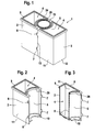
Der Darstellung gemäß Figur 1 ist eine konfektionierte, an ihrer Oberseite noch offene Reagenzkassette gemäß der vorliegenden Erfindung zu entnehmen.The representation according to FIG. 1 is a prefabricated, still open on its upper side Reagent cassette according to the present invention can be seen.
Eine Reagenzkassette 1 wird durch einen ersten, einen Behälter bildenden Kassettenteil 2
sowie einen zweiten, ebenfalls einen Behälter bildenden Kassettenteil 3 gebildet. Die
Behälter bildenden Kassettenteile 2, 3 sind an ihren einander zuweisenden Seiten jeweils
mit einer Wölbung 5 versehen. Zwischen den Wölbungen 5 der Kassettenteile 2, 3 befindet
sich ein Behälter 20 (Beadflasche). Der Behälter 20 weist an seiner Oberseite eine als
Schweißfläche ausgebildete Ringfläche 24 auf, ebenso wie die die Behälter bildenden
Kassettenteile 2, 3 an ihrer Oberseite eine Schweißfläche 9 aufweisen. Der Behälter 20
dient der Aufnahme einer partikelhaltigen Reagenz, während in Hohlräume 4 der Behälter
bildenden Kassettenteile 2, 3 als Flüssigkeit beschaffene Reagenzien eingefüllt werden
können. An ihren als Schweißflächen ausgebildeten Oberseiten 9, 24 können die
Kassettenteile 2, 3 beziehungsweise der als Beadflasche ausgebildete Behälter 20 mit einer
Folie verschweißt werden, um den Inhalt des Behälters 20 beziehungsweise der Behälter
bildenden Kassettenteile 2, 3 gegen Kontamination zu schützen. A reagent cartridge 1 is formed by a
Wie aus der Darstellung gemäß Figur 1 hervorgeht, liegen die die Behälter bildenden
Kassettenteile 2, 3 entlang einer Stoßfuge 13 aneinander an. Das Fügen der Behälter
bildenden Kassettenteile 2, 3 an der Stoßfuge 13 erfolgt über Rastöffnungen 6, in welche
Rastnasen 7 eingreifen. Die in Figur 1 im zusammengefügten Zustand dargestellte
Reagenzkassette 1 umfasst eine großflächige Seitenwand 11 und eine Stirnwand 12,
welche große Planflächen zum Aufbringen einer Etikettierung bieten. Die die Behälter
bildenden Kassettenteile 2, 3 werden vorzugsweise als Spritzgießbauteile hergestellt, an
welchen in einem Arbeitsgang an den jeweiligen Kassettenteilen 2, 3 sowohl die Rastnasen
7 als auch die Rastöffnungen 9 sowie die Wölbungen 5 ausgebildet werden können.As can be seen from the illustration according to FIG. 1, the containers form the
Der Darstellung gemäß Figur 2 ist eines der beiden miteinander fügbaren Kassettenteile der Reagenzkassette zu entnehmen.The illustration according to FIG. 2 is one of the two cassette parts which can be joined together remove the reagent cartridge.
Der Darstellung gemäß Figur 2 ist zu entnehmen, dass der einen Behälter bildende
Kassettenteil 2 auf der Seite der Wölbung 5 eine halbkreisförmig ausgebildete Einfassung
29 sowie eine Positionierhilfe 10 aufweist. Die Positionierhilfe 10 ist in der Darstellung
gemäß Figur 2 halbkreisförmig ausgebildet. Im Bereich der Seitenwand 11 befinden sich
die Rastnasen 6, während an der gegenüberliegenden Seitenwand die Rastnasen 7
ausgebildet sind. Den Hohlraum 4 des Kassettenteils 2 umschließend ist an der Oberseite
des einen Behälter bildenden Kassettenteils 2 eine Schweißfläche 9 ausgebildet.The representation according to Figure 2 it can be seen that the one container forming
In der Darstellung gemäß Figur 3 ist das in Figur 2 dargestellte, einen Behälter bildende Kassettenteil im Schnitt wiedergegeben.In the illustration according to FIG. 3, the container shown in FIG. 2 is formed Cassette part reproduced in section.
Aus der Darstellung gemäß Figur 3 geht hervor, dass der Hohlraum 4 des einen Behälter
bildenden Kassettenteils 2 durch einen Hohlraumboden 8 begrenzt wird, der hinsichtlich
des Totvolumens optimiert ist. Unter Totvolumen wird im vorliegenden Zusammenhang
das Reagenzvolumen verstanden, was aus dem Hohlraum 4 des Kassettenteils 2 nicht mehr
entnehmbar ist.The illustration according to FIG. 3 shows that the
Die Schweißfläche 9 an der Oberseite des einen Behälter bildenden Kassettenteils 2 ist für
eine Doppelversiegelung ausgelegt, d.h. die Schweißfläche 9 kann gestuft ausgebildet sein,
so dass ein Aufschweißen mehrfach übereinanderliegender Folien zum Verschluss
(Doppelversiegelung) des Hohlraumes 4 des einen Behälter bildenden Kassettenteils 2
möglich ist. Die als Viertelkreis in der Darstellung gemäß Figur 3 dargestellte Einfassung
29 sowie die ebenfalls als Viertelkreis dargestellte Positionierhilfe 10 dienen der drehbaren
Lagerung eines in Figur 3 nicht dargestellten Behälters 20, in welchem eine partikelhaltige
Reagenz aufgenommen ist. An der hinteren Seitenwand 11 des einen Behälter bildenden
Kassettenteils 2 sind vorspringende Rastnasen 7 angespritzt, welche im Wege des
Kunststoffspritzgießverfahrens in einem Arbeitsgang während der Herstellung des als
Behälter ausgebildeten Kassettenteils 2 angespritzt werden können.The
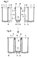
Figur 4.1 zeigt einen als Beadflasche ausgebildeten Behälter zur Aufnahme einer partikelhaltigen Reagenz.FIG. 4.1 shows a container designed as a bead bottle for holding a container particle-containing reagent.
Der Behälter 20 umfasst an seiner Oberseite eine Ringfläche 24, an welcher eine Folie
aufschweißbar ist, um nach Befüllen des Behälters 20 mit einer partikelhaltigen Reagenz
dessen Innenraum gegen Kontamination zu schützen. An der Oberseite des als Beadflasche
ausgebildeten Behälters 20 ist insbesondere ein Positionierring 22 ausgebildet, welcher mit
der an den als Behälter ausgebildeten Kassettenteilen 2, 3 angeordneten Einfassung 29
zusammenwirkt. Am Boden des Behälters 20 ist ein geschlitzter Kunststoffring 21
angespritzt. Auch der das partikelhaltige Reagenz aufnehmende Behälter 20 (Beadflasche)
kann im Wege des Kunststoffspritzgießverfahrens in einem Arbeitsgang kostengünstig
hergestellt werden.The
Aus der Darstellung gemäß Figur 4.2 geht der Behälter 20 im Schnitt hervor.From the illustration in Figure 4.2, the
Unterhalb der an der Oberseite des Behälters 20 (Beadflasche) ausgebildeten Ringfläche
befindet sich der Positionierring 22. Im unteren Bereich des Behälters 20 ist dieser an
seiner Innenseite mit einer spiralförmigen Struktur 23 in Wendelform versehen. Die die
Wendelform darstellende spiralförmige Struktur 23 erzeugt bei intermittierendem Drehen
eine vertikale Strömung im zylindrischen Wandbereich des Behälters 20 sowie eine
entgegenlaufende vertikale Strömung im Zentrum des Behälters 20. Zum Ausgleich
entsteht am Flaschenboden eine definierte, sich in radiale Richtung erstreckende Strömung,
die sehr gut geeignet ist, die im Bodenbereich des Behälters 20 sedimentierten Partikel zu
resuspendieren. Der flache Winkel der spiralförmigen Struktur 23, bezogen auf die
Flüssigkeitsoberfläche, ermöglicht eine schonende Strömungserzeugung ohne
Kavitationserscheinungen und verhindert definitiv Schaumbildung im Inneren des
Behälters 20 und eine Beschädigung von Partikeln, die optional mit einer Beschichtung
versehen sein können.Below the ring surface formed at the top of the container 20 (bead bottle)
is the
Der Behälter 20 wird durch einen Flaschenboden 30 begrenzt. Unterhalb des
Flaschenbodens ist an den Behälter 20 (Beadflasche) ein geschlitzter Ring 21 angespritzt.
Der geschlitzte Ring umfasst durch Schlitze voneinander getrennte Laschen 34, die federnd
ausgebildet sind und welche eine Kupplungsverbindung mit einem in Figur 4.2 nicht
dargestellten Kupplungsstück 31 ermöglichen.The
Aus der perspektivisch dargestellten Figur 4.3 geht hervor, dass sich die spiralförmige
Struktur 23 in Wendelform entlang der beiden unteren Drittel des Behälters 20
(Beadflasche) erstreckt. Der Flaschenboden 30 ist kegelstumpfförmig ausgebildet.
Unterhalb des Flaschenbodens 30 ist an den Behälter 20 zur Aufnahme einer
partikelhaltigen Reagenz ein geschlitzter Ring 21 angespritzt, dessen einzelne durch
Schlitze voneinander getrennte Laschen 34 federnd ausgebildet sind, um ein einfaches
Kuppeln mit einem Kupplungsstück an einem Magazin zu ermöglichen.From the perspective shown in Figure 4.3 shows that the
Figur 5 zeigt eine konfektionierte Reagenzkassette, zwei Behälter bildende Kassettenteile
und eine zwischen diesen aufgenommenen, eine partikelhaltige Reagenz aufnehmenden
Behälter 20 umfassend.Figure 5 shows a ready-made reagent cassette, two cassette-forming cassette parts
and a particle-receiving reagent received
Aus der Darstellung gemäß Figur 5 geht hervor, dass der das partikelhaltige Reagenz
aufnehmende Behälter 20 drehbar zwischen den jeweils Behälter bildenden Kassettenteilen
2 und 3 gelagert ist. Der Behälter 20 (Beadflasche) wird einerseits durch die
halbkreisförmigen Positionierhilfen 10 der als Behälter dienenden Kassettenteile 2, 3
oberhalb des geschlitzten Ringes 21 fixiert, und andererseits durch die oberhalb des
Positionierringes 22 anliegenden halbkreisförmigen Einfassungen 29. In der Darstellung
gemäß Figur 5 ist zwischen den Behälter bildenden Kassettenteilen 2, 3 ein Behälter 20
gelagert, der als Beadflasche ausgebildet ist. Der in Figur 5 dargestellte Behälter 20
umfasst eine spiralförmige Struktur in Wendelform 23, die sich oberhalb des
Flaschenbodens 30 erstreckt. Aus der in Figur 5 im konfektionierten Zustand 26
dargestellten Reagenzkassette 1 geht hervor, dass im konfektionierten Zustand die
Reagenzkassette 3 voneinander getrennte Behälter aufweist. Es sind dies die Hohlräume 4
des Kassettenteils 2 sowie des Kassettenteils 3 sowie der Hohlraum des Behälters 20 zur
Aufnahme der partikelhaltigen Reagenz. Die Hohlräume 4 der Kassettenteile 2 und 3
sowie der Hohlraum des Behälters 20 werden jeweils durch einen Totvolumen optimierten
Boden 8 sowie durch einen kegelstumpfförmigen Boden 30 begrenzt.The illustration according to FIG. 5 shows that the particle-containing
Aus der Darstellung gemäß Figur 5 geht hervor, dass sowohl der einen Behälter bildende
Kassettenteil 2 als auch der einen Behälter bildende Kassettenteil 3 jeweils eine
Standfläche aufweisen. Der an dem Behälter 20 zur Aufnahme der partikelhaltigen
Reagenz ausgebildete geschlitzte Ring 21 stellt ebenfalls eine ebene Standfläche dar. Im
konfektionierten Zustand 26 bilden die Standflächen der Kassettenteile 2, 3
beziehungsweise des Behälters 20 zur Aufnahme der partikelhaltigen Reagenz eine ebene
Unterseite 28 der Reagenzkassette 1 im konfektionierten Zustand 26. An der Oberseite der
Reagenzkassette 1 im konfektionierten Zustand 26 sind als Schweißflächen dienende
Flächen 9 ausgebildet; an der Oberseite des Behälters 20 zur Aufnahme der
partikelhaltigen Reagenz befindet sich die ebenfalls als Schweißfläche dienende
Ringfläche 24.The illustration according to FIG. 5 shows that both the one container forming
Aus der Darstellung gemäß Figur 5 ist ferner entnehmbar, dass der geschlitzte Ring 21
mehrere durch Schlitze voneinander getrennte federnde Laschen 34 aufweist. Mit
Bezugszeichen 5 sind die gewölbten Flächen der Behälter bildenden Kassettenteile 2, 3
identifiziert, die einen Hohlraum zwischen den Positionierhilfen 10 und dem
Positionierring 22 bilden, wenn die Behälter bildenden Kassettenteile 2, 3
ineinandergefügt, d.h. zusammengesteckt sind.From the illustration according to FIG. 5, it can also be seen that the slotted
Aus der Darstellung gemäß Figur 6 geht eine Schnittdarstellung der in Figur 5 dargestellten Reagenzkassette im konfektionierten Zustand hervor.The illustration according to FIG. 6 is a sectional view of that in FIG. 5 shown reagent cassette in the assembled state.
Der zwischen den Behälter bildenden Kassettenteile 2, 3 drehbar gelagerte Behälter 20 zur
Aufnahme einer partikelhaltigen Reagenz 20 wird durch die Einfassungen 29 und dem
Positionierring 22, der am Behälter 20 angespritzt ist, im oberen Bereich gelagert, während
die drehbare Lagerung des Behälters 20 (Beadflasche) im unteren Bereich durch die
halbkreisförmig ausgebildeten Positionierhilfen 10 erfolgt, die an der Unterseite der
gewölbten Flächen 5 der Kassettenteile 2, 3 angespritzt sind. Jedes der Behälter bildenden
Kassettenteile 2, 3 umfasst einen Totvolumen-optimierten Boden 8 (vgl. Darstellung
gemäß Figur 3).The between the container forming
In der Darstellung gemäß Figur 6 ist zwischen den Behälter bildenden Kassettenteilen 2, 3
ein Behälter 20 eingelassen, der eine spiralförmige Struktur 23 in Wendelform auf seiner
Innenseite aufweist. Bei Rotation des Behälters 20 über den Laschen 34 enthaltenden
geschlitzten Ring 21 wird durch die spiralförmige Struktur 23 in Wendelform an der
Innenseite des Behälters 20 eine Homogenisierung der partikelhaltigen Reagenz im
Behälter 20 (Beadflasche) erreicht, wodurch durch Sedimentation aufgetretene
Konzentrationsunterschiede im partikelhaltigen Reagenz ausgeglichen werden können, d.h.
eine gleichmäßige Partikelverteilung innerhalb der partikelhaltigen Reagenz erreicht
werden kann. In the illustration according to FIG. 6,
Die Stirnwände 12 der Reagenzkassette 1 im konfektionierten Zustand 26 können zum
Aufbringen von Etiketten genutzt werden. Gleiches gilt für die zwischen den Stirnwänden
12 liegende Seitenwand 11 der Reagenzkassette 1 im konfektionierten Zustand 26. Entlang
der Stoßfuge 13 liegen die Behälter bildenden Kassettenteile 2, 3 aneinander an; aus
Gründen der zeichnerischen Darstellungen sind die miteinander zusammenwirkenden
Rastöffnungen 6 beziehungsweise Rastnasen 7 entlang der Stoßfuge 13 in den Figuren 5
und 6 nicht dargestellt.The
Figur 7 sind die einzelnen Behälter, aus denen die erfindungsgemäß vorgeschlagene Reagenzkassette gefügt wird, zu entnehmen.FIG. 7 shows the individual containers from which the proposed invention Reagent cassette is added, refer to.
Die jeweils im Schnitt dargestellten Kassettenteile 2, 3 sowie der Behälter 20 werden in
Richtung der Pfeile miteinander gefügt. Beim Fügen, d.h. Aufeinanderzubewegen der
Behälter bildenden Kassettenteile 2, 3 rasten die Rastnasen 7 des einen Behälter bildenden
Kassettenteils 2 in die Rastöffnungen 6 des anderen, einen Behälter bildenden
Kassettenteils 3 ein. Während des Fügens wird der Behälter 20 (Beadflasche) zur
Aufnahme einer partikelhaltigen Reagenz so zwischen den miteinander zu fügenden
Kassettenteilen 2, 3 ausgerichtet, dass der Positionierring 22 unterhalb der Einfassungen 29
an der Oberseite der beiden Kassettenteile 2 zur Anlage kommt. Die beiden am unteren
Bereich der Behälter bildenden Kassettenteile 2, 3 angeordneten Positionierhilfen 10
umschließen den Behälter 20 oberhalb des geschlitzten Ringes 21, der federnd ausgebildete
Laschen 34 aufweist. Dadurch wird eine drehbare Lagerung des eine partikelhaltige
Reagenz aufnehmenden Behälters 20 (Beadflasche) in einer in Figur 8 dargestellten
Reagenzkassette im konfektionierten Zustand 26 erreicht. Aufgrund der Ausbildung der
Standfläche des einen Behälter bildenden Kassettenteils 2 sowie des anderen, einen
Behälter bildenden Kassettenteils 3 und der Geometrie des geschlitzten Ringes 21 wird im
konfektionierten Zustand 26 der Reagenzkassette 1 eine ebene Unterseite 28 erhalten.
Aufgrund der Fügbarkeit der einzelnen Behälter, d.h. der Kassettenteile 2 und 3 und des
Behälters 20 (Beadflasche), kann eine Abfüllung von Reagenzien und eine
Kassettenkonfektionierung demzufolge zeitlich unabhängig voneinander erfolgen. Wie aus
den Darstellungen gemäß der Figuren 7 und 8 hervorgeht, folgt ein Fügen der
erfindungsgemäß vorgeschlagenen Reagenzkassette 1 durch einfaches Zusammenstecken
der Komponenten 2, 3 und 20, ohne dass weitere Zusatzteile wie beispielsweise Deckel
oder halsförmig ausgebildete Fügeelemente erforderlich wären. The
Der Darstellung gemäß Figur 9 ist ein Kupplungsstück entnehmbar, mit welchem der geschlitzte Ring an der Unterseite des die partikelhaltige Reagenz aufnehmenden Behälters gefügt wird.The illustration according to Figure 9, a coupling piece can be removed, with which the slotted ring at the bottom of the container containing the particle-containing reagent is added.
Das in Figur 9 dargestellte Kupplungsstück 31 weist einen scheibenförmig ausgebildeten
Sockel 32 sowie einen an diesem ausgebildeten Kupplungskopf 33 auf. Beim Aufstecken
der Reagenzkassette 1 im konfektionierten Zustand 26 gemäß Figur 8 rastet der geschlitzte
Ring, d.h. dessen federnd ausgebildete Laschen 34 am Kupplungskopf 33 ein. Die federnd
ausgebildeten, durch Schlitze voneinander getrennten Laschen 34 umschließen den
Kupplungskopf 33 zur Gänze. Durch den geschlitzten Ring 21, ausgebildet an dem in
Rotation zu versetzenden Behälter 20 zur Aufnahme einer partikelhaltigen Reagenz, und
dem Kupplungsstück 31 wird eine Kupplungsverbindung hergestellt, durch welche eine
Rotation in den die partikelhaltige Reagenz aufnehmenden Behälter 20 (Beadflasche)
eingeleitet werden kann. Das Einrasten der federnd ausgebildeten Laschen 34 des
geschlitzten Ringes 21 unterstützt ferner die korrekte Positionierung des Behälters 20
innerhalb der Reagenzkassette 1 und ist vorteilhaft für eine reibungsarme Flaschenrotation
innerhalb der Reagenzkassette 1 im konfektionierten Zustand 26. Das Einrasten des
geschlitzten Ringes 21 am Kupplungsstück 31 erfolgt bei manueller oder automatischer
Bestückung eines Reagenzmagazins, wie nachfolgend noch beschrieben wird.The
Der Vollständigkeit halber sei erwähnt, dass die in Figur 7 beispielsweise dargestellte
Rastverbindung zwischen den Rastöffnungen 6 und der Rastnasen 7 an den miteinander zu
fügenden Behälter bildenden Kassettenteilen 2, 3 auch so ausgestaltet werden kann, dass
ein zerstörungsfreies Lösen der beiden Kassettenteile voneinander nicht möglich ist.For completeness, it should be mentioned that the example shown in Figure 7
Locking connection between the latching
Aus der Darstellung gemäß Figur 10 geht in schematischer Ansicht ein Reagenzmagazin hervor.From the illustration according to FIG. 10, a reagent magazine is shown in a schematic view out.
Das Reagenzmagazin 40 umfasst im Wesentlichen einen Magazinteller 41, der von einer
zentralen Welle 46 gehalten ist. Der Magazinteller 41 rotiert im Drehsinn 42, angedeutet
durch den mit Bezugszeichen 42 identifizierten Pfeil. Anstelle des in Figur 10 dargestellten
Magazintellers 41, der eine denkbare Ausführungsvariante darstellt; kann das
Reagenzmagazin 40 auch in Matrixanordnung ausgebildet sein. Im Magazinteller 41 sind
mehrere Kupplungsstücke 31 eingelassen. Die Kupplungsstücke 31 werden ihrerseits von
einer Antriebswelle 45 angetrieben, die über ein Getriebe 44 mit einem Antrieb 43 in
Verbindung steht. Auf der Oberseite des Magazintellers 41 sind Reagenzkassetten 1 im
fertig konfektionierten Zustand 26 positioniert. Aufgrund der eben ausgebildeten
Unterseite 28 der Reagenzkassetten 1 im konfektionierten Zustand 26 stehen diese plan auf
der Oberseite des Magazintellers 41 auf. Die Reagenzkassetten 1 im konfektionierten
Zustand 26 sind so auf der Oberseite des Magazintellers 41 positioniert, dass der
geschlitzte Ring eines Behälters 20 einer Reagenzkassette 1 im konfektionierten Zustand
26 die angetriebenen Kupplungsstücke 31 am Magazinteller 41 umgreift. Dadurch wird
eine Kupplungsverbindung zwischen der drehbar in der Reagenzkassette 1 im
konfektionierten Zustand 26 gelagerten Behälter 20 zur Aufnahme einer partikelhaltigen
Reagenz geschaffen. Durch den Antrieb 43, das Getriebe 44 sowie die Antriebswelle 45
des Kupplungsstückes 31 wird der drehbar in der Reagenzkassette 1 gelagerte Behälter 20
zur Aufnahme einer partikelhaltigen Reagenz in Rotation versetzt, während die
Reagenzkassette 1 im konfektionierten Zustand 26 in ihrer Position an der Oberseite des
Magazintellers 41 verbleibt. Damit können in einer Reagenzkassette 1 drei Reagenzien
aufgenommen sein, von denen das zu homogenisierende, da sedimentierende Partikel
enthaltende Reagenz in der über die Kupplungsverbindung 21, 31 angetriebenen Behälter
20 (Beadflasche) enthalten ist. In einem Arbeitsgang lassen sich demnach pro
Reagenzkassette 1 mehrere Reagenzien für eine Weiterverarbeitung vorbereiten. Aus der
Darstellung gemäß Figur 10 hervor, dass an der Oberseite des Magazintellers 41
entsprechend der Anzahl der angetriebenen Kupplungsstücke 31 mehrere
Reagenzkassetten 1 parallel behandelt werden können. Die Behälter bildenden
Kassettenteile 2, 3 sind jeweils über die Rastverschlüsse 6, 7, Rastöffnungen 6 und
Rastnasen 7 umfassend, lösbar miteinander verbunden, wobei die Klipsverbindung
zwischen den die Behälter bildenden Kassettenteile 2, 3 auch so gestaltet werden kann,
dass ein zerstörungsfreies Lösen nicht mehr möglich ist.The
Aus der Darstellung gemäß Figur 11 geht in schematischer Ansicht ein Reagenzmagazin in Matrixanordnung hervor.From the illustration according to FIG. 11, a reagent magazine is shown in a schematic view Matrix arrangement forth.
Der Darstellung gemäß Figur 11 sind Reagenzkassetten zu entnehmen, die das erste
Behälter bildende Kassettenteil 2 (R1-Flasche) und das zweite Behälter bildende
Kassettenteil 3 aufweisen. Die Kassettenteile 2 beziehungsweise 3 sind durch eine
Rastverbindung, gegeben durch die Rastöffnung 6 und die darin einrastende Rastnase 7
miteinander verbunden. Die beiden in Figur 11 in einem Reagenzmagazin 47 in
Matrixanordnung aufgenommenen Reagenzkassetten stehen mit ihren ebenen Unterseiten
28 auf einem Teller 48 des Reagenzmagazins 47 in Matrixanordnung auf. Die
Reagenzkassetten sind an ihrer Oberseite geschlossen und enthalten einzelne Behälter 20
(Beadflaschen). Die Beadflaschen 20 sind mit Hilfe von Positionierringen 22 gesichert und
im Bereich ihres Flaschenbodens 30 mit dem Kupplungsstück 31 gekoppelt. Das
Kupplungsstück 31 wiederum ist durch eine Antriebswelle 52 angetrieben, die mit einem
Riemenrad oder dergleichen versehen ist und beispielsweise durch einen Zahnriemen 51
angetrieben werden kann. Der Zahnriemen 51 umschließt ein weiteres Antriebsrad,
welches die in Figur 11 auf der linken Seite der Figur dargestellte Reagenzkassette,
bestehend aus dem ersten Behälter bildenden Kassettenteil 2 und dem zweiten Behälter
bildenden Kassettenteil 3 angeordnet ist. Der Zahnriemen 51 wird über ein
Antriebszahnrad 50 eines Antriebes 49 angetrieben und versetzt mittels Antriebswellen 52,
der Kupplungsstücke 31, die an der Unterseite im Bereich des Flaschenbodens 30 durch
das Kupplungsstück 31 angekoppelten Behälter 20 (Beadflaschen) innerhalb der
Reagenzkassetten in Rotation.The illustration according to FIG. 11 shows reagent cartridges which are the first
Container forming cassette part 2 (R1 bottle) and the second container forming
Mit der in Figur 11 dargestellten Ausführungsvarianten können in einer Reagenzkassette
drei Reagenzien in verschiedenen Behältern 20 (Beadflaschen) aufgenommen sein, von
denen die mittlere über das Kupplungsstück 31, die Antriebswelle 52, den Zahnriemen 51
und den Antrieb 49 zu homogenisierende Reagenz enthaltende Behälterflasche 20 in
Rotation versetzbar ist. Damit lassen sich in einem Arbeitsgang ähnlich wie in der in Figur
10 dargestellten Ausführungsvariante pro Reagenzkassette 1 mehrere Reagenzien für eine
Weiterverarbeitung vorbereiten. Die zu homogenisierende, da sedimentierende Partikel
enthaltende Reagenz ist dabei vorzugsweise in der über die Kupplungsverbindung 31, 52
angetriebenen Behälter 20 (Beadflasche) aufgenommen. Entsprechend der Größe der
Tellerfläche des Tellers 48 für das Reagenzmagazin 47 in Matrixanordnung und
entsprechend der Anzahl der über den Zahnriemen 51 angetriebenen Antriebswellen 52
kann eine Vielzahl von Reagenzkassetten 1 in Matrixanordnung in dem in Figur 11
dargestellten Reagenzmagazin 47 in Matrixanordnung behandelt werden. With the embodiment variants shown in FIG. 11, in a reagent cassette
three reagents may be included in different containers 20 (bead bottles), from
which the middle of the
- 11
- Reagenzkassettereagent cartridge
- 22
-
erstes Behälter bildendes Kassettenteil
(R1-Flasche)first container forming cassette part
(R1-bottle) - 33
-
zweites Behälter bildendes Kassettenteil
(R2-Flasche)second container forming cassette part
(R2 bottle) - 44
- Hohlraumcavity
- 55
- gewölbte Seitearched side
- 66
- Rastöffnunglatching opening
- 77
- Rastnaselocking lug
- 88th
- HohlraumbodenRaised floor
- 99
- Schweißflächewelding surface
- 1010
- Positionierhilfepositioning
- 1111
- SeitenwandSide wall
- 1212
- Stirnwandbulkhead
- 1313
- Stoßfugebutt joint
- 2020
- Behälter (Beadflasche)Container (bead bottle)
- 2121
- geschlitzter Ringslotted ring
- 2222
- Positionierringpositioning
- 2323
- spiralförmige Struktur (Wendelform)helical structure (spiral shape)
- 2424
- Ringfläche (gestufte Schweißfläche)Ring surface (stepped welding surface)
- 2626
- konfektionierte Reagenzkassettepre-assembled reagent cassette
- 2727
- Oberseite ReagenzkassetteTop of the reagent cassette
- 2828
- ebene Unterseite Reagenzkassettelevel bottom reagent cartridge
- 2929
- Einfassungmount
- 3030
- Flaschenbodenbottle bottom
- 3131
- Kupplungsstückcoupling
- 3232
- Sockelbase
- 3333
- Kupplungskopfcoupling head
- 3434
-
federnde Laschen Schlitzring 21resilient tabs slit
ring 21
- 4040
- ReagenzmagazinReagenzmagazin
- 4141
- Magazintellermagazine plate
- 4242
- Drehsinn rotation
- 4343
- Antriebdrive
- 4444
- Getriebetransmission
- 4545
- Antriebswelle für KupplungsstückDrive shaft for coupling piece
- 4646
- zentrale Wellecentral shaft
- 4747
- Reagenzmagazin in MatrixanordnungReagent magazine in matrix arrangement
- 4848
- Teller in MatrixanordnungPlate in matrix arrangement
- 4949
- Antriebdrive
- 5050
- Antriebszahnraddrive gear
- 5151
- Zahnriementoothed belt
- 5252
- Antriebswelledrive shaft
Claims (15)
Applications Claiming Priority (2)
| Application Number | Priority Date | Filing Date | Title |
|---|---|---|---|
| DE10360526 | 2003-12-22 | ||
| DE10360526A DE10360526A1 (en) | 2003-12-22 | 2003-12-22 | Reagent cassette with reagent container for particle-containing reagent for its noninvasive homogenization |
Publications (3)
| Publication Number | Publication Date |
|---|---|
| EP1550498A2 true EP1550498A2 (en) | 2005-07-06 |
| EP1550498A3 EP1550498A3 (en) | 2005-11-30 |
| EP1550498B1 EP1550498B1 (en) | 2008-07-30 |
Family
ID=34559770
Family Applications (1)
| Application Number | Title | Priority Date | Filing Date |
|---|---|---|---|
| EP04029815A Not-in-force EP1550498B1 (en) | 2003-12-22 | 2004-12-16 | Reagent cartridge with reagent containers for reagents containing particles for their non-invasive homogenization |
Country Status (7)
| Country | Link |
|---|---|
| US (1) | US7790108B2 (en) |
| EP (1) | EP1550498B1 (en) |
| JP (1) | JP4106050B2 (en) |
| AT (1) | ATE402755T1 (en) |
| CA (1) | CA2490085C (en) |
| DE (2) | DE10360526A1 (en) |
| ES (1) | ES2311776T3 (en) |
Cited By (1)
| Publication number | Priority date | Publication date | Assignee | Title |
|---|---|---|---|---|
| US9632103B2 (en) | 2013-03-15 | 2017-04-25 | Abbott Laboraties | Linear track diagnostic analyzer |
Families Citing this family (18)
| Publication number | Priority date | Publication date | Assignee | Title |
|---|---|---|---|---|
| JP4787026B2 (en) * | 2006-01-20 | 2011-10-05 | 凸版印刷株式会社 | Reaction vessel |
| FR2904114B1 (en) * | 2006-07-21 | 2008-10-17 | Biocode Hycel France Sa Sa | CARTRIDGE FOR REACTIVE PRODUCTS FOR USE IN ANALYTICAL APPARATUSES, CARRIER FOR RECEIVING THIS CARTRIDGE, AND ANALYSIS ASSEMBLY COMPRISING SAID CARTRIDGE AND HOLDER |
| US7731414B2 (en) | 2007-02-08 | 2010-06-08 | Instrumentation Laboratory Company | Reagent cartridge mixing tube |
| WO2009090989A1 (en) * | 2008-01-15 | 2009-07-23 | Kyowa Medex Co., Ltd. | Reagent container |
| US20100159498A1 (en) * | 2008-12-19 | 2010-06-24 | Ritzen Kalle | Blood analyzer with a blood cell sedimentation control mechanism and method of use |
| JP2010202269A (en) * | 2009-03-05 | 2010-09-16 | Beckman Coulter Inc | Reaction card manufacturing device |
| JP6012728B2 (en) * | 2012-06-25 | 2016-10-25 | 協和メデックス株式会社 | Cassette and reagent set |
| USD962471S1 (en) | 2013-03-13 | 2022-08-30 | Abbott Laboratories | Reagent container |
| USD978375S1 (en) | 2013-03-13 | 2023-02-14 | Abbott Laboratories | Reagent container |
| US9535082B2 (en) | 2013-03-13 | 2017-01-03 | Abbott Laboratories | Methods and apparatus to agitate a liquid |
| US10058866B2 (en) | 2013-03-13 | 2018-08-28 | Abbott Laboratories | Methods and apparatus to mitigate bubble formation in a liquid |
| WO2014144825A2 (en) | 2013-03-15 | 2014-09-18 | Abbott Laboratories | Automated reagent manager of a diagnostic analyzer system |
| WO2014144870A2 (en) | 2013-03-15 | 2014-09-18 | Abbott Laboratories | Light-blocking system for a diagnostic analyzer |
| CN105143890B (en) * | 2013-04-22 | 2017-08-29 | 株式会社日立高新技术 | Automatic analysing apparatus |
| US9724657B2 (en) * | 2013-10-22 | 2017-08-08 | Tyme, Inc. | High-speed centrifugal mixing devices and methods of use |
| USD848636S1 (en) | 2015-10-20 | 2019-05-14 | Roche Diagnostics Operations, Inc. | Reagent container |
| CN111812320B (en) * | 2020-07-28 | 2023-04-25 | 山东圣剑医学研究有限公司 | Detection kit of full-automatic immunoassay device |
| CN112973520A (en) * | 2021-02-07 | 2021-06-18 | 浙江交投丽新矿业有限公司 | A compound green equipment for mine ecological remediation |
Citations (4)
| Publication number | Priority date | Publication date | Assignee | Title |
|---|---|---|---|---|
| EP0651254A1 (en) * | 1993-10-28 | 1995-05-03 | F. Hoffmann-La Roche Ag | Reagent kit and analyser in which it may be used |
| JPH10151125A (en) * | 1996-11-21 | 1998-06-09 | Corp Miyuki:Kk | Person discriminating system by dna |
| EP0937983A1 (en) * | 1992-04-09 | 1999-08-25 | F. Hoffmann-La Roche Ag | Automatic analyser |
| US6149872A (en) * | 1995-11-02 | 2000-11-21 | Byk-Sangtec Diagnostica Gmbh & Co. Kg | Modular reagent cartridge |
Family Cites Families (17)
| Publication number | Priority date | Publication date | Assignee | Title |
|---|---|---|---|---|
| US3415361A (en) * | 1966-12-22 | 1968-12-10 | Miles Lab | Test device and container therefor |
| US2413094A (en) * | 1944-12-09 | 1946-12-24 | Remington Arms Co Inc | Metal treating apparatus |
| CH444126A (en) * | 1965-09-08 | 1967-09-30 | Inventa Ag | Device for the continuous implementation of chemical reactions in viscous liquids |
| EP0252632B1 (en) * | 1986-07-11 | 1994-08-31 | Beckman Instruments, Inc. | Reagent cartridge |
| JPS6415125A (en) * | 1987-07-07 | 1989-01-19 | Sanko Air Plant | Mixer for particulate matter |
| US5183638A (en) * | 1989-12-04 | 1993-02-02 | Kabushiki Kaisha Nittec | Automatic immunity analysis apparatus with magnetic particle separation |
| ATE157459T1 (en) * | 1989-12-22 | 1997-09-15 | Alfa Biotech Spa | DEVICE FOR SELECTIVE STIRRING REACTION COMPONENTS |
| GB9020352D0 (en) * | 1990-09-18 | 1990-10-31 | Anagen Ltd | Assay or reaction apparatus |
| US5380487A (en) * | 1992-05-05 | 1995-01-10 | Pasteur Sanofi Diagnostics | Device for automatic chemical analysis |
| US5428997A (en) | 1992-07-20 | 1995-07-04 | Pasteur Sanofi Diagnostics | Method of and device for fluid surface detection using an ultrasonic transducer |
| US5772962A (en) * | 1995-05-29 | 1998-06-30 | Hitachi, Ltd. | Analyzing apparatus using disposable reaction vessels |
| US5637962A (en) * | 1995-06-09 | 1997-06-10 | The Regents Of The University Of California Office Of Technology Transfer | Plasma wake field XUV radiation source |
| US5609822A (en) * | 1995-07-07 | 1997-03-11 | Ciba Corning Diagnostics Corp. | Reagent handling system and reagent pack for use therein |
| EP0835452B1 (en) * | 1996-04-26 | 2005-08-10 | Dade Behring Inc. | Method and apparatus for pre-treating samples in an automatic chemical analyzer |
| US5856194A (en) * | 1996-09-19 | 1999-01-05 | Abbott Laboratories | Method for determination of item of interest in a sample |
| US5795784A (en) * | 1996-09-19 | 1998-08-18 | Abbott Laboratories | Method of performing a process for determining an item of interest in a sample |
| RU2191630C1 (en) * | 2001-06-09 | 2002-10-27 | Общество с ограниченной ответственностью "Кварц Т-2000" | Low-frequency acoustic generator |
-
2003
- 2003-12-22 DE DE10360526A patent/DE10360526A1/en not_active Withdrawn
-
2004
- 2004-12-13 CA CA2490085A patent/CA2490085C/en not_active Expired - Fee Related
- 2004-12-16 AT AT04029815T patent/ATE402755T1/en active
- 2004-12-16 ES ES04029815T patent/ES2311776T3/en active Active
- 2004-12-16 DE DE502004007729T patent/DE502004007729D1/en active Active
- 2004-12-16 EP EP04029815A patent/EP1550498B1/en not_active Not-in-force
- 2004-12-21 JP JP2004369506A patent/JP4106050B2/en not_active Expired - Fee Related
- 2004-12-22 US US11/021,071 patent/US7790108B2/en not_active Expired - Fee Related
Patent Citations (4)
| Publication number | Priority date | Publication date | Assignee | Title |
|---|---|---|---|---|
| EP0937983A1 (en) * | 1992-04-09 | 1999-08-25 | F. Hoffmann-La Roche Ag | Automatic analyser |
| EP0651254A1 (en) * | 1993-10-28 | 1995-05-03 | F. Hoffmann-La Roche Ag | Reagent kit and analyser in which it may be used |
| US6149872A (en) * | 1995-11-02 | 2000-11-21 | Byk-Sangtec Diagnostica Gmbh & Co. Kg | Modular reagent cartridge |
| JPH10151125A (en) * | 1996-11-21 | 1998-06-09 | Corp Miyuki:Kk | Person discriminating system by dna |
Cited By (1)
| Publication number | Priority date | Publication date | Assignee | Title |
|---|---|---|---|---|
| US9632103B2 (en) | 2013-03-15 | 2017-04-25 | Abbott Laboraties | Linear track diagnostic analyzer |
Also Published As
| Publication number | Publication date |
|---|---|
| JP4106050B2 (en) | 2008-06-25 |
| DE10360526A1 (en) | 2005-07-14 |
| US20050153426A1 (en) | 2005-07-14 |
| US7790108B2 (en) | 2010-09-07 |
| DE502004007729D1 (en) | 2008-09-11 |
| EP1550498B1 (en) | 2008-07-30 |
| CA2490085A1 (en) | 2005-06-22 |
| ATE402755T1 (en) | 2008-08-15 |
| JP2005181338A (en) | 2005-07-07 |
| EP1550498A3 (en) | 2005-11-30 |
| ES2311776T3 (en) | 2009-02-16 |
| CA2490085C (en) | 2011-02-15 |
Similar Documents
| Publication | Publication Date | Title |
|---|---|---|
| EP1550498B1 (en) | Reagent cartridge with reagent containers for reagents containing particles for their non-invasive homogenization | |
| DE60030310T2 (en) | MIXING AND CASTING APPARATUS WITH ROTATABLE ARM AND ASSOCIATED VESSEL | |
| EP1344500B1 (en) | Multiple component mixing capsule, particularly for dental purpose | |
| EP1940539B1 (en) | One-trip container comprising a stirring device | |
| DE69725787T2 (en) | Stirrer and toner cartridge with stirrer | |
| DE19908181A1 (en) | Apparatus for dispensing fluid from a container | |
| EP2514515B1 (en) | Method for mixing a first and a second component | |
| DE102009030305A1 (en) | Stirring device with collapsible agitator blade | |
| EP1474235A1 (en) | Sample preparation device and test device set based thereon | |
| DE19735539A1 (en) | Mixer for small-scale application | |
| DE19819447A1 (en) | Device and method for mixing and washing liquids and / or solids | |
| WO2019201605A1 (en) | System for packaging two components | |
| EP2371343B1 (en) | Device for storing and metering a solution | |
| DE1950067A1 (en) | Automatic chemical analysis | |
| WO2005002729A1 (en) | Use of a disposable container, microfluidic device and method for processing molecules | |
| DE60203487T2 (en) | FLEXIBLE CONTAINER AND METHOD FOR THE PRODUCTION THEREOF | |
| DE102004030155A1 (en) | Dosing device and method for operating the same | |
| DE102008017083A1 (en) | Apparatus for equilibrium dialysis of liquids | |
| DE4428664C2 (en) | Container, arrangement and method for producing, storing and dispensing an individual formulation | |
| EP3490699B1 (en) | Modular stirring mechanism | |
| DE19900347A1 (en) | Pipetting and mixing unit rotates tip continuously or oscillates it back and forth for stirring action on solids, liquids and gases, in simple, effective design particularly suited for automatic microbiological testing apparatus | |
| DE2659627A1 (en) | DEVICE FOR THE SEPARATION OF CHEMICAL SUBSTANCES WITH THE GENERATION OF STERILE SOLUTIONS | |
| EP2559633A1 (en) | Bucket lid with integrated chamber | |
| DE202007005884U1 (en) | Container with flexible walls | |
| DE102015011881B4 (en) | Mixing system and method for mixing a fluid and / or a solid |
Legal Events
| Date | Code | Title | Description |
|---|---|---|---|
| PUAI | Public reference made under article 153(3) epc to a published international application that has entered the european phase |
Free format text: ORIGINAL CODE: 0009012 |
|
| AK | Designated contracting states |
Kind code of ref document: A2 Designated state(s): AT BE BG CH CY CZ DE DK EE ES FI FR GB GR HU IE IS IT LI LT LU MC NL PL PT RO SE SI SK TR |
|
| AX | Request for extension of the european patent |
Extension state: AL BA HR LV MK YU |
|
| PUAL | Search report despatched |
Free format text: ORIGINAL CODE: 0009013 |
|
| AK | Designated contracting states |
Kind code of ref document: A3 Designated state(s): AT BE BG CH CY CZ DE DK EE ES FI FR GB GR HU IE IS IT LI LT LU MC NL PL PT RO SE SI SK TR |
|
| AX | Request for extension of the european patent |
Extension state: AL BA HR LV MK YU |
|
| RIC1 | Information provided on ipc code assigned before grant |
Ipc: 7B 65D 21/02 B Ipc: 7B 01F 15/00 B Ipc: 7B 01L 3/00 B Ipc: 7B 01F 9/00 B Ipc: 7B 01F 3/12 A |
|
| 17P | Request for examination filed |
Effective date: 20060112 |
|
| AKX | Designation fees paid |
Designated state(s): AT BE BG CH CY CZ DE DK EE ES FI FR GB GR HU IE IS IT LI LT LU MC NL PL PT RO SE SI SK TR |
|
| 17Q | First examination report despatched |
Effective date: 20060328 |
|
| GRAP | Despatch of communication of intention to grant a patent |
Free format text: ORIGINAL CODE: EPIDOSNIGR1 |
|
| RAP1 | Party data changed (applicant data changed or rights of an application transferred) |
Owner name: F. HOFFMANN-LA ROCHE AG Owner name: ROCHE DIAGNOSTICS GMBH |
|
| GRAS | Grant fee paid |
Free format text: ORIGINAL CODE: EPIDOSNIGR3 |
|
| GRAA | (expected) grant |
Free format text: ORIGINAL CODE: 0009210 |
|
| AK | Designated contracting states |
Kind code of ref document: B1 Designated state(s): AT BE BG CH CY CZ DE DK EE ES FI FR GB GR HU IE IS IT LI LT LU MC NL PL PT RO SE SI SK TR |
|
| REG | Reference to a national code |
Ref country code: GB Ref legal event code: FG4D Free format text: NOT ENGLISH |
|
| REG | Reference to a national code |
Ref country code: CH Ref legal event code: EP |
|
| REG | Reference to a national code |
Ref country code: CH Ref legal event code: NV Representative=s name: BOHEST AG |
|
| REF | Corresponds to: |
Ref document number: 502004007729 Country of ref document: DE Date of ref document: 20080911 Kind code of ref document: P |
|
| REG | Reference to a national code |
Ref country code: IE Ref legal event code: FG4D Free format text: LANGUAGE OF EP DOCUMENT: GERMAN |
|
| PG25 | Lapsed in a contracting state [announced via postgrant information from national office to epo] |
Ref country code: LT Free format text: LAPSE BECAUSE OF FAILURE TO SUBMIT A TRANSLATION OF THE DESCRIPTION OR TO PAY THE FEE WITHIN THE PRESCRIBED TIME-LIMIT Effective date: 20080730 Ref country code: IS Free format text: LAPSE BECAUSE OF FAILURE TO SUBMIT A TRANSLATION OF THE DESCRIPTION OR TO PAY THE FEE WITHIN THE PRESCRIBED TIME-LIMIT Effective date: 20081130 Ref country code: PT Free format text: LAPSE BECAUSE OF FAILURE TO SUBMIT A TRANSLATION OF THE DESCRIPTION OR TO PAY THE FEE WITHIN THE PRESCRIBED TIME-LIMIT Effective date: 20081230 Ref country code: NL Free format text: LAPSE BECAUSE OF FAILURE TO SUBMIT A TRANSLATION OF THE DESCRIPTION OR TO PAY THE FEE WITHIN THE PRESCRIBED TIME-LIMIT Effective date: 20080730 |
|
| REG | Reference to a national code |
Ref country code: ES Ref legal event code: FG2A Ref document number: 2311776 Country of ref document: ES Kind code of ref document: T3 |
|
| PG25 | Lapsed in a contracting state [announced via postgrant information from national office to epo] |
Ref country code: BG Free format text: LAPSE BECAUSE OF FAILURE TO SUBMIT A TRANSLATION OF THE DESCRIPTION OR TO PAY THE FEE WITHIN THE PRESCRIBED TIME-LIMIT Effective date: 20081030 Ref country code: SI Free format text: LAPSE BECAUSE OF FAILURE TO SUBMIT A TRANSLATION OF THE DESCRIPTION OR TO PAY THE FEE WITHIN THE PRESCRIBED TIME-LIMIT Effective date: 20080730 Ref country code: FI Free format text: LAPSE BECAUSE OF FAILURE TO SUBMIT A TRANSLATION OF THE DESCRIPTION OR TO PAY THE FEE WITHIN THE PRESCRIBED TIME-LIMIT Effective date: 20080730 |
|
| REG | Reference to a national code |
Ref country code: IE Ref legal event code: FD4D |
|
| PG25 | Lapsed in a contracting state [announced via postgrant information from national office to epo] |
Ref country code: EE Free format text: LAPSE BECAUSE OF FAILURE TO SUBMIT A TRANSLATION OF THE DESCRIPTION OR TO PAY THE FEE WITHIN THE PRESCRIBED TIME-LIMIT Effective date: 20080730 Ref country code: IE Free format text: LAPSE BECAUSE OF FAILURE TO SUBMIT A TRANSLATION OF THE DESCRIPTION OR TO PAY THE FEE WITHIN THE PRESCRIBED TIME-LIMIT Effective date: 20080730 Ref country code: DK Free format text: LAPSE BECAUSE OF FAILURE TO SUBMIT A TRANSLATION OF THE DESCRIPTION OR TO PAY THE FEE WITHIN THE PRESCRIBED TIME-LIMIT Effective date: 20080730 |
|
| PG25 | Lapsed in a contracting state [announced via postgrant information from national office to epo] |
Ref country code: CZ Free format text: LAPSE BECAUSE OF FAILURE TO SUBMIT A TRANSLATION OF THE DESCRIPTION OR TO PAY THE FEE WITHIN THE PRESCRIBED TIME-LIMIT Effective date: 20080730 Ref country code: SK Free format text: LAPSE BECAUSE OF FAILURE TO SUBMIT A TRANSLATION OF THE DESCRIPTION OR TO PAY THE FEE WITHIN THE PRESCRIBED TIME-LIMIT Effective date: 20080730 Ref country code: RO Free format text: LAPSE BECAUSE OF FAILURE TO SUBMIT A TRANSLATION OF THE DESCRIPTION OR TO PAY THE FEE WITHIN THE PRESCRIBED TIME-LIMIT Effective date: 20080730 |
|
| PLBE | No opposition filed within time limit |
Free format text: ORIGINAL CODE: 0009261 |
|
| STAA | Information on the status of an ep patent application or granted ep patent |
Free format text: STATUS: NO OPPOSITION FILED WITHIN TIME LIMIT |
|
| BERE | Be: lapsed |
Owner name: F. HOFFMANN-LA ROCHE A.G. Effective date: 20081231 Owner name: ROCHE DIAGNOSTICS G.M.B.H. Effective date: 20081231 |
|
| 26N | No opposition filed |
Effective date: 20090506 |
|
| PG25 | Lapsed in a contracting state [announced via postgrant information from national office to epo] |
Ref country code: MC Free format text: LAPSE BECAUSE OF NON-PAYMENT OF DUE FEES Effective date: 20081231 |
|
| PG25 | Lapsed in a contracting state [announced via postgrant information from national office to epo] |
Ref country code: BE Free format text: LAPSE BECAUSE OF NON-PAYMENT OF DUE FEES Effective date: 20081231 |
|
| PG25 | Lapsed in a contracting state [announced via postgrant information from national office to epo] |
Ref country code: SE Free format text: LAPSE BECAUSE OF FAILURE TO SUBMIT A TRANSLATION OF THE DESCRIPTION OR TO PAY THE FEE WITHIN THE PRESCRIBED TIME-LIMIT Effective date: 20081030 |
|
| PG25 | Lapsed in a contracting state [announced via postgrant information from national office to epo] |
Ref country code: PL Free format text: LAPSE BECAUSE OF FAILURE TO SUBMIT A TRANSLATION OF THE DESCRIPTION OR TO PAY THE FEE WITHIN THE PRESCRIBED TIME-LIMIT Effective date: 20080730 |
|
| PG25 | Lapsed in a contracting state [announced via postgrant information from national office to epo] |
Ref country code: HU Free format text: LAPSE BECAUSE OF FAILURE TO SUBMIT A TRANSLATION OF THE DESCRIPTION OR TO PAY THE FEE WITHIN THE PRESCRIBED TIME-LIMIT Effective date: 20090131 Ref country code: CY Free format text: LAPSE BECAUSE OF FAILURE TO SUBMIT A TRANSLATION OF THE DESCRIPTION OR TO PAY THE FEE WITHIN THE PRESCRIBED TIME-LIMIT Effective date: 20080730 Ref country code: LU Free format text: LAPSE BECAUSE OF NON-PAYMENT OF DUE FEES Effective date: 20081216 |
|
| PG25 | Lapsed in a contracting state [announced via postgrant information from national office to epo] |
Ref country code: TR Free format text: LAPSE BECAUSE OF FAILURE TO SUBMIT A TRANSLATION OF THE DESCRIPTION OR TO PAY THE FEE WITHIN THE PRESCRIBED TIME-LIMIT Effective date: 20080730 |
|
| PG25 | Lapsed in a contracting state [announced via postgrant information from national office to epo] |
Ref country code: GR Free format text: LAPSE BECAUSE OF FAILURE TO SUBMIT A TRANSLATION OF THE DESCRIPTION OR TO PAY THE FEE WITHIN THE PRESCRIBED TIME-LIMIT Effective date: 20081031 |
|
| PGFP | Annual fee paid to national office [announced via postgrant information from national office to epo] |
Ref country code: GB Payment date: 20131126 Year of fee payment: 10 Ref country code: AT Payment date: 20131126 Year of fee payment: 10 Ref country code: CH Payment date: 20131029 Year of fee payment: 10 |
|
| PGFP | Annual fee paid to national office [announced via postgrant information from national office to epo] |
Ref country code: ES Payment date: 20131211 Year of fee payment: 10 Ref country code: FR Payment date: 20131126 Year of fee payment: 10 Ref country code: IT Payment date: 20131217 Year of fee payment: 10 |
|
| PGFP | Annual fee paid to national office [announced via postgrant information from national office to epo] |
Ref country code: DE Payment date: 20131230 Year of fee payment: 10 |
|
| REG | Reference to a national code |
Ref country code: CH Ref legal event code: PCAR Free format text: NEW ADDRESS: HOLBEINSTRASSE 36-38, 4051 BASEL (CH) |
|
| REG | Reference to a national code |
Ref country code: DE Ref legal event code: R119 Ref document number: 502004007729 Country of ref document: DE |
|
| REG | Reference to a national code |
Ref country code: CH Ref legal event code: PL |
|
| REG | Reference to a national code |
Ref country code: AT Ref legal event code: MM01 Ref document number: 402755 Country of ref document: AT Kind code of ref document: T Effective date: 20141216 |
|
| GBPC | Gb: european patent ceased through non-payment of renewal fee |
Effective date: 20141216 |
|
| REG | Reference to a national code |
Ref country code: FR Ref legal event code: ST Effective date: 20150831 |
|
| PG25 | Lapsed in a contracting state [announced via postgrant information from national office to epo] |
Ref country code: DE Free format text: LAPSE BECAUSE OF NON-PAYMENT OF DUE FEES Effective date: 20150701 Ref country code: GB Free format text: LAPSE BECAUSE OF NON-PAYMENT OF DUE FEES Effective date: 20141216 Ref country code: LI Free format text: LAPSE BECAUSE OF NON-PAYMENT OF DUE FEES Effective date: 20141231 Ref country code: CH Free format text: LAPSE BECAUSE OF NON-PAYMENT OF DUE FEES Effective date: 20141231 |
|
| PG25 | Lapsed in a contracting state [announced via postgrant information from national office to epo] |
Ref country code: AT Free format text: LAPSE BECAUSE OF NON-PAYMENT OF DUE FEES Effective date: 20141216 Ref country code: FR Free format text: LAPSE BECAUSE OF NON-PAYMENT OF DUE FEES Effective date: 20141231 |
|
| PG25 | Lapsed in a contracting state [announced via postgrant information from national office to epo] |
Ref country code: IT Free format text: LAPSE BECAUSE OF NON-PAYMENT OF DUE FEES Effective date: 20141216 |
|
| REG | Reference to a national code |
Ref country code: ES Ref legal event code: FD2A Effective date: 20160127 |
|
| PG25 | Lapsed in a contracting state [announced via postgrant information from national office to epo] |
Ref country code: ES Free format text: LAPSE BECAUSE OF NON-PAYMENT OF DUE FEES Effective date: 20141217 |