EP1550012B1 - Chronographuhr - Google Patents
Chronographuhr Download PDFInfo
- Publication number
- EP1550012B1 EP1550012B1 EP02785776A EP02785776A EP1550012B1 EP 1550012 B1 EP1550012 B1 EP 1550012B1 EP 02785776 A EP02785776 A EP 02785776A EP 02785776 A EP02785776 A EP 02785776A EP 1550012 B1 EP1550012 B1 EP 1550012B1
- Authority
- EP
- European Patent Office
- Prior art keywords
- locking device
- display means
- pusher
- control device
- measured time
- Prior art date
- Legal status (The legal status is an assumption and is not a legal conclusion. Google has not performed a legal analysis and makes no representation as to the accuracy of the status listed.)
- Expired - Lifetime
Links
- 238000005259 measurement Methods 0.000 claims abstract description 13
- 230000000903 blocking effect Effects 0.000 claims description 6
- 210000000056 organ Anatomy 0.000 claims 6
- 230000007246 mechanism Effects 0.000 description 29
- 208000031968 Cadaver Diseases 0.000 description 7
- 230000000694 effects Effects 0.000 description 5
- 230000009471 action Effects 0.000 description 3
- 230000008901 benefit Effects 0.000 description 2
- 239000000470 constituent Substances 0.000 description 2
- 230000009977 dual effect Effects 0.000 description 2
- XLYOFNOQVPJJNP-UHFFFAOYSA-N water Substances O XLYOFNOQVPJJNP-UHFFFAOYSA-N 0.000 description 2
- 229910000906 Bronze Inorganic materials 0.000 description 1
- 229910000831 Steel Inorganic materials 0.000 description 1
- 244000245420 ail Species 0.000 description 1
- 229910052790 beryllium Inorganic materials 0.000 description 1
- ATBAMAFKBVZNFJ-UHFFFAOYSA-N beryllium atom Chemical compound [Be] ATBAMAFKBVZNFJ-UHFFFAOYSA-N 0.000 description 1
- 239000010974 bronze Substances 0.000 description 1
- 239000003086 colorant Substances 0.000 description 1
- KUNSUQLRTQLHQQ-UHFFFAOYSA-N copper tin Chemical compound [Cu].[Sn] KUNSUQLRTQLHQQ-UHFFFAOYSA-N 0.000 description 1
- 230000000994 depressogenic effect Effects 0.000 description 1
- 230000001627 detrimental effect Effects 0.000 description 1
- 238000006073 displacement reaction Methods 0.000 description 1
- 230000009189 diving Effects 0.000 description 1
- 239000013013 elastic material Substances 0.000 description 1
- 238000012423 maintenance Methods 0.000 description 1
- 235000020004 porter Nutrition 0.000 description 1
- 239000010453 quartz Substances 0.000 description 1
- 238000009877 rendering Methods 0.000 description 1
- 230000000717 retained effect Effects 0.000 description 1
- 230000035939 shock Effects 0.000 description 1
- VYPSYNLAJGMNEJ-UHFFFAOYSA-N silicon dioxide Inorganic materials O=[Si]=O VYPSYNLAJGMNEJ-UHFFFAOYSA-N 0.000 description 1
- 239000010959 steel Substances 0.000 description 1
- 230000007704 transition Effects 0.000 description 1
Images


Classifications
-
- G—PHYSICS
- G04—HOROLOGY
- G04F—TIME-INTERVAL MEASURING
- G04F7/00—Apparatus for measuring unknown time intervals by non-electric means
- G04F7/04—Apparatus for measuring unknown time intervals by non-electric means using a mechanical oscillator
- G04F7/08—Watches or clocks with stop devices, e.g. chronograph
- G04F7/0823—Watches or clocks with stop devices, e.g. chronograph with couplings between the chronograph mechanism and the base movement
- G04F7/0838—Watches or clocks with stop devices, e.g. chronograph with couplings between the chronograph mechanism and the base movement involving a tilting movement
-
- G—PHYSICS
- G04—HOROLOGY
- G04F—TIME-INTERVAL MEASURING
- G04F7/00—Apparatus for measuring unknown time intervals by non-electric means
- G04F7/04—Apparatus for measuring unknown time intervals by non-electric means using a mechanical oscillator
- G04F7/08—Watches or clocks with stop devices, e.g. chronograph
- G04F7/0866—Special arrangements
Definitions
- This watch further comprises a housing housing for movement and having at least one pusher for controlling the control devices and zeroing.
- Some of these watches have only one pushbutton controlling the two devices, others, more frequent, include two separate pushers.
- Such watches are susceptible to untimely maneuvers. Thus, a shock on one of the pushers can cause the unexpected stop of a measurement in progress. Such a situation can also occur in diving, where the pressure of the water acts on the start-stop pushbutton until it can interrupt a measurement in progress, which can be, to say the least, detrimental.
- the document CH 104 374 discloses a locking device of the only reset mechanism.
- the watch of the invention is characterized in that it further comprises a locking device arranged to cooperate with the control device, and capable of occupying first and second positions in which the device control may or may not be activated, and an actuating member intended to be accessible from the outside of the box for controlling the locking device. Thanks to this locking device, it is thus possible to prevent any accidental manipulation.
- Chronograph-type watches are of course known in which the pushers can be screwed to the middle of the case so as to improve the seal. It is clear that a screwed pusher becomes inoperative. Such an operation, however, requires some attention, each pusher to be locked by itself.
- the control member may as well be a pusher a crown, depending on the desired purpose.
- the controller be inactive as long as the timed time display means displays this other information.
- the locking device is arranged so as to be able to act on the control device only when the timed time display means are at zero or display information other than the timed time.
- an action on the control member, and by it on the locking device makes the control device operable and leads to zero needle providing a dual display.
- the control member is advantageously a pusher.
- the locking device is arranged so as to make the zeroing device also actuable or not.
- the locking device advantageously comprises a locking piece which acts on the pusher to immobilize it. In this way, the pusher can not be moved accidentally, neither by a movement of the user, nor by the pressure of the water during dive.
- the locking device comprises a movable connecting piece arranged so that, depending on the position it occupies, a pressure on the pusher is or is not transmitted to the control mechanism.
- the locking device further comprises an apparent display member on the dial of the watch, to indicate which position occupies the locking device. and, consequently, whether the control device is operable or not.
- the actuating member may be formed of a crown pivotally mounted on the box. It can also be formed of a pusher.
- the watch represented on the figure 1 is chronograph type. It comprises, in a conventional manner, a box 10 serving as a housing for a movement, which carries a dial 12, hands of the hours of current time 14, minutes of current time and of timed time 16 and seconds of timed time 20.
- the display of the current time is corrected by means of a time setting ring 22, connected to the movement members by a time-setting rod not visible in the drawing.
- the functions relating to the timing are provided by three pushers 24, 26 and 28 respectively arranged at two hours, four hours and eight hours.
- the pusher 24 controls the start and stop of a measurement of timed time, while the pusher 26 ensures the zeroing of the hands 16 and 20 when a measurement of timed time has been interrupted.
- the pusher 28 makes it possible to move the chronograph mechanism from a first state, in which it is locked, to a second state in which it is unlocked.
- the needle 16 When the chronograph mechanism is locked, the needle 16 displays the minutes of current time, while when it is unlocked, it indicates the timed time. In the locked state, the pushers 24 and 26 are inactive. To allow the passage from one to the other of these states, the mechanism comprises a locking device which will be described in more detail below and which has the effect of rendering inoperative the pusher 24 when the mechanism is locked, while the pusher 28 is off when a measurement is in progress.
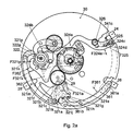
- This mechanism is part of a movement which comprises, in a conventional manner and not visible in the drawing, a source of energy such as a barrel, a time base such as a sprung balance, a work train, of which only a mobile 29 is visible on the figure 2a , and an escapement connecting the work train to the pendulum for maintenance, as well as time setting and chronograph mechanisms.
- the various components of the movement are arranged on a frame 30, formed of a plate and bridges, which ensures the relative positioning of the various moving parts.
- the chronograph mechanism represented on the Figures 2a and 2b which is described in detail in the patent application EP 02022505.8 , allows the display of the minutes of timed time and the current time with the single needle 16.
- the part of the mechanism relating to the commands "start-stop” and “zeroing” could be replaced without any other mechanism of existing chronograph.
- the mechanism shown in the drawing essentially comprises locking, control and zeroing devices, the parts of which are parts are identified by the first two digits of their reference beginning respectively with 32, 34 and 36.
- the springs that comprise this mechanism are schematically represented by arrows identified by the letter "F” followed by the number corresponding to the reference of the part on which it acts. The arrow is oriented approximately in the direction in which the spring exerts its force.
- the zeroing device 36 is formed in particular by a lever 361 and a hammer 362.
- the lever 361 is provided with a pin 361a arranged facing the pusher 26 and a groove 361b placed so that it can serve as a housing for the pin 321h when the finger 321d bears against a column of the 342.
- a spring F361 tends to push the lever 361 in support against the pusher.
- the hammer is also subjected to an elastic force by a spring F362 keeping it bearing against the wheel 322.
- the hammer 362 will not be described in more detail it is intended to cooperate with cams carried by the wheels of the chronograph wheel bearing needles, to zero them. Such devices are well known to those skilled in the art.
- the pusher 24 acts on the lever 341 via the stud 325, which bears against the folding 341c. Also, when the pad 325 is not interposed between the folding 341c and the pusher 24, a pressure on the latter is without effect.
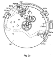
- Pressing the pusher again 28 rotates the column wheel 322 so that the nose 324b is raised and the stud 325 moves away from the pusher 24, which becomes inactive again.
- the lever 361 tilts and releases the pin 321h.
- the body 321a tilts under the effect of the spring F321a, and with it the lever 321k.
- the pin 321m is again facing the pusher 28 which becomes active again. The movement of the body 321 releases, in addition, the hammer 362 which controls the zeroing of the minute hands of time timed.
- the chronograph mechanism By pressing on the pusher 28, the chronograph mechanism returns to its locked state and the minute hand 16 goes from zero to the display of the current time, as explained above.
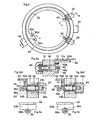
- the figure 3 represents a watch which can be seen the box 10, the setting ring 22 and two pushers 24 and 26.
- the figure 3a can also see the dial 12.
- the ring 22 is used to set the time information about the current time, the pusher 24 to control the start and stop of a chronograph mechanism, and the pusher 26 to zero.
- This watch is represented on the figure 3a cut according to a plane AA perpendicular to the drawing and on Figures 3b 1 and 3b 2 cut along a plane BB also perpendicular, in the locked position of the pusher 24 in 3b 1 and free in 3b 2 .
- the Figures 3c and 3d show, seen from the side as indicated by the arrows C and D, part of the watch respectively in the locked and free position of the pushers.
- chronograph mechanism is represented only schematically, by a portion of control lever 40 and zeroing lever 42, these portions cooperating respectively with the pushers 24 and 26.
- This mechanism can be of n ' any type controlled by two pushers.
- the box 10 carries, in addition, at 8 o'clock, a second ring 44, which, as can be seen on the figure 3a is secured to a rod 46 passing through the wall of the box 10.
- the rod 46 is provided with a pinion 48 mounted on a square 46a of the rod 46 and held by a screw 50 engaged in a thread formed in the rod 46 .
- the watch is, furthermore, equipped with a ring 52 disposed inside the box 10, adjacent to the inner wall of the caseband and the dial 12, which forms with the ring 44, the rod 46 and the pinion 48 , a locking device of the pushers 24 and 26.
- the ring 52 is provided, in its adjacent portion of the ring 44, a toothed gear sector 52a which meshes with the toothing of the pinion 48, thus allowing its driving in rotation, over a limited angle. As will be explained below, the ring 52 is intended to block the pushers 24 and 26.
- the Figures 3b 1 and 3b 2 represent the pusher 24 in section, engaged in the box 10, respectively in locked and free positions.
- a tube 54 driven into a hole which is provided with the box 10, serves as a housing for the pusher 24.
- the latter is formed of an outer button 24a, on which the user presses, and a rod 24b screwed on the button 24a and engaged in the tube 54.
- a seal 24c is housed on the rod 24b and bears against the inner end of the button 24a, while a coil spring 55 surrounds the rod 24b and is supported by a part in the bottom of the tube 54, on the other hand against the seal 24c ensuring the return of the pusher 24 when subjected to pressure.
- a washer may advantageously be interposed between the spring 55 and the seal 24c.
- the pusher 24 is held in the box 10 by means of a screw 56 engaged in a threaded hole in the rod 24b, which is not visible in the drawing.
- This screw is provided with a head 56a which cooperates with the lever 40 to control the chronograph mechanism.
- the head 56a has a groove 56b extending radially in its cylindrical portion.
- the ring 52 comprises a cylindrical portion 52b of inner and outer diameters and height such that this portion can be engaged in the groove 56b, as shown in FIG. figure 3c .
- the portion 52b is provided with a rounded cutout 52c, arranged so that, when aligned with the pusher 24, the groove is released, which makes possible the movement of the pusher 24.
- the cutout 52c is aligned on the axis B-B, so that the pusher 24 can be activated.
- the ring 52 is engaged in the groove 56b, thus blocking the pusher 24.
- the two extreme positions of the ring 52 can be defined by a jumper which has not been shown in the drawing, which would have the advantage of clearly marking these two positions.
- the ring 52 is provided with a display area 52c having two marks, for example of different colors 52d and 52e, which appear on the screen. one or the other in a window 12a of the dial 12, thus showing which position occupies the ring 52 and, in this way, whether the mechanism is in function or locked.
- the ring 52 is made of elastic material, for example steel or beryllium bronze. It also comprises a cylindrical portion 52b, but in which are cut lamellae 52f, integral with the cylindrical portion at one of their ends, free and forming, by folding, a finger 52g at the other end. This finger 52g is at the same level as the screw head 56a. In this way, if the blade 52f is opposite the screw head 56a, an action on the pusher 24 causes the screw head 56a to bear against the blade 52f, the finger 52g pushing the lever 40. In the vicinity of the folding 52g, the cylindrical portion is interrupted, so that by rotating the ring to bring it to its second position, the blade is no longer opposite the screw head 56a, the displacement of the pusher 24 then taking place in a vacuum.
- control member could also be provided by the time setting ring 22 in its depressed position, especially in the case where the movement comprises a quartz time base and a source of electrical energy.
Landscapes
- Physics & Mathematics (AREA)
- General Physics & Mathematics (AREA)
- Measurement Of Unknown Time Intervals (AREA)
- Electromechanical Clocks (AREA)
- Electric Clocks (AREA)
Claims (9)
- Uhr vom Typ Chronograph, mit einem Uhrwerk (29) ausgestattet, aufweisend:- Mittel für die Anzeige der laufenden Zeit,- Mittel für die Anzeige einer gemessenen Zeit,- eine Zeitbasis, die ausgebildet ist, um die Anzeigemittel zu regeln,- eine Steuervorrichtung (34, 40), die den Start und den Stopp der Mittel zur Anzeige der gemessenen Zeit gewährleistet,- eine Vorrichtung zur Nullstellung, um die Mittel zur Anzeige der gemessenen Zeit nach Beendigung einer Messung auf Null zurückzustellen,und ein Gehäuse (10), das dem Uhrwerk (29) als Aufnahme dient und mindestens einen Drücker (24) umfasst, der dazu bestimmt ist, die Vorrichtungen zu steuern, dadurch gekennzeichnet, dass die Uhr weiterhin eine Verriegelungsvorrichtung (32, 52) umfasst, die ausgebildet ist, um mit der Steuervorrichtung (34, 40) zusammenzuarbeiten und imstande, erste und zweite Stellungen einzunehmen, in denen die Steuervorrichtung (34, 40) aktiviert sein kann oder nicht, und ein Betätigungsorgan (28, 44), das dazu bestimmt ist, von außerhalb des Gehäuses (10) zugänglich zu sein, um die Verriegelungsvorrichtung (32, 52) zu steuern.
- Uhr nach Anspruch 1, dadurch gekennzeichnet, dass die Mittel zur Anzeige der gemessenen Zeit weiterhin die Anzeige einer anderen Information als der gemessenen Zeit erlauben und dadurch, dass die Verriegelungsvorrichtung (32) derart ausgebildet ist, dass sie nur dann auf die Steuervorrichtung (34) einwirken kann, wenn die Mittel zur Anzeige der gemessenen Zeit auf Null sind oder eine andere Information als die gemessene Zeit anzeigen.
- Uhr nach Anspruch 1, dadurch gekennzeichnet, dass die Verriegelungsvorrichtung (52) derart ausgebildet ist, um mit der Vorrichtung zur Nullstellung (42) zusammenzuarbeiten, damit sie betätigbar ist oder nicht.
- Uhr nach einem der Ansprüche 1 bis 3, dadurch gekennzeichnet, dass die Verriegelungsvorrichtung (52b) ein Blockierteil umfasst, das auf den Drücker (24, 26) einwirkt, um ihn zu blockieren.
- Uhr nach einem der Ansprüche 1 bis 4, dadurch gekennzeichnet, dass die Verriegelungsvorrichtung (32, 52b) ein bewegliches Verbindungsteil (325, 52f) umfasst, das derart angeordnet ist, dass je nach Stellung, die es einnimmt, ein Druck auf den Drücker (24, 26) auf die Steuervorrichtung (34, 40) übertragen wird oder nicht.
- Uhr nach einem der Ansprüche 1 bis 5, dadurch gekennzeichnet, dass die Verriegelungsvorrichtung (52) weiterhin ein Anzeigeorgan (52c) umfasst, das anzuzeigen erlaubt, ob die Steuervorrichtung (52) betätigbar ist oder nicht.
- Uhr nach Anspruch 1, dadurch gekennzeichnet, dass das Betätigungsorgan (44) von einer Krone (44) gebildet wird, die drehbar auf dem Gehäuse (10) montiert ist.
- Uhr nach Anspruch 7, dadurch gekennzeichnet, dass das Betätigungsorgan eine Welle (46) umfasst, die durch das Gehäuse (10) angeordnet ist und dazu bestimmt, an ihrem äußeren Ende die Krone (44) zu tragen, und einen Trieb (48) an ihrem Ende im Gehäuse (10), und dadurch, dass die Verriegelungsvorrichtung umfasst:- einen das Uhrwerk (29) umgebenden Ring (52), der auf einem Abschnitt seines dem Trieb (48) benachbarten Randes mit einer Zahnung (52a) ausgestattet ist und imstande, zwei Stellungen einzunehmen, wobei der Übergang von der einen zur anderen durch eine Drehbewegung erfolgt, und- ein zwischengestelltes Organ (52b, 52f), das mit dem Ring (52) verbunden ist und mit dem Drücker (24) zusammenarbeitet, damit dieser auf die Steuervorrichtung (40) einwirken kann oder nicht.
- Uhr nach Anspruch 1, dadurch gekennzeichnet, dass das Betätigungsorgan von einem Drücker (28) gebildet wird, der gleitend auf dem Gehäuse (10) montiert ist.
Priority Applications (1)
| Application Number | Priority Date | Filing Date | Title |
|---|---|---|---|
| EP02785776A EP1550012B8 (de) | 2002-10-07 | 2002-12-02 | Chronographuhr |
Applications Claiming Priority (4)
| Application Number | Priority Date | Filing Date | Title |
|---|---|---|---|
| EP02022505A EP1408383B1 (de) | 2002-10-07 | 2002-10-07 | Chronographenuhrwerk |
| EP02022505 | 2002-10-07 | ||
| PCT/IB2002/005054 WO2004031290A2 (fr) | 2002-10-07 | 2002-12-02 | Montre de type chronographe |
| EP02785776A EP1550012B8 (de) | 2002-10-07 | 2002-12-02 | Chronographuhr |
Publications (3)
| Publication Number | Publication Date |
|---|---|
| EP1550012A2 EP1550012A2 (de) | 2005-07-06 |
| EP1550012B1 true EP1550012B1 (de) | 2010-02-10 |
| EP1550012B8 EP1550012B8 (de) | 2010-05-19 |
Family
ID=69322564
Family Applications (1)
| Application Number | Title | Priority Date | Filing Date |
|---|---|---|---|
| EP02785776A Expired - Lifetime EP1550012B8 (de) | 2002-10-07 | 2002-12-02 | Chronographuhr |
Country Status (7)
| Country | Link |
|---|---|
| US (1) | US7232254B2 (de) |
| EP (1) | EP1550012B8 (de) |
| JP (1) | JP4370252B2 (de) |
| AT (1) | ATE457480T1 (de) |
| AU (1) | AU2002351064A1 (de) |
| DE (1) | DE60235328D1 (de) |
| WO (1) | WO2004031290A2 (de) |
Families Citing this family (11)
| Publication number | Priority date | Publication date | Assignee | Title |
|---|---|---|---|---|
| EP1408383B1 (de) * | 2002-10-07 | 2006-01-25 | Vaucher Manufacture Fleurier SA | Chronographenuhrwerk |
| JP4304199B2 (ja) * | 2006-09-26 | 2009-07-29 | セイコープレシジョン株式会社 | 計時機器、計時システムおよびタイム計測方法 |
| ATE466316T1 (de) * | 2007-02-14 | 2010-05-15 | Maurice Lacroix Sa | Mechanismus zur umschaltbaren übertragung |
| USD566586S1 (en) * | 2007-10-24 | 2008-04-15 | Invicta Watch Company Of America, Inc. | Watch |
| NL1037424C2 (nl) | 2009-10-29 | 2011-05-02 | Atte Nicolaas Bakker | Chronograaf. |
| JP5536623B2 (ja) * | 2010-02-03 | 2014-07-02 | セイコーインスツル株式会社 | クロノグラフ時計 |
| JP2011247873A (ja) * | 2010-04-30 | 2011-12-08 | Seiko Instruments Inc | クロノグラフ時計 |
| WO2013033666A1 (en) * | 2011-09-01 | 2013-03-07 | Stefan Johansson | Timepiece case with integrated pusher and crown |
| JP5926566B2 (ja) * | 2012-01-31 | 2016-05-25 | シチズンホールディングス株式会社 | 多機能時計用ムーブメントおよび多機能時計 |
| JP6121023B2 (ja) * | 2016-04-22 | 2017-04-26 | シチズン時計株式会社 | 多機能時計用ムーブメントおよび多機能時計 |
| EP4202570B1 (de) * | 2021-12-23 | 2024-07-03 | Montres Breguet S.A. | Uhrwerk mit einer sekundenstopp-funktion, die von zwei verschiedenen steuerorganen aus betätigt werden kann |
Family Cites Families (8)
| Publication number | Priority date | Publication date | Assignee | Title |
|---|---|---|---|---|
| CH104374A (fr) * | 1923-05-07 | 1924-05-01 | Leon Breitling Montbrillant Wa | Compteur de temps. |
| GB1405102A (en) * | 1971-08-20 | 1975-09-03 | Smiths Industries Ltd | Stop watches |
| IT1285148B1 (it) * | 1996-06-03 | 1998-06-03 | Panerai Off Srl | Dispositivo per il bloccaggio della lunetta girevole di orologi,in particolare orologi subacquei, e di tenuta stagna della corona di |
| JP2899967B1 (ja) * | 1998-01-07 | 1999-06-02 | セイコーインスツルメンツ株式会社 | クロノグラフ時計の発停レバーばね |
| WO1999054792A1 (en) * | 1998-04-21 | 1999-10-28 | Seiko Epson Corporation | Time measuring device |
| EP1048988A3 (de) * | 1999-04-27 | 2001-05-16 | Alain Mouawad | Verriegelungsvorrichtung für eine Uhrenaufzugskrone |
| JP4959082B2 (ja) * | 1999-10-14 | 2012-06-20 | シチズンホールディングス株式会社 | 電子時計及び電子時計の駆動方法 |
| US6975561B2 (en) * | 2002-06-13 | 2005-12-13 | Vaucher Manufacture Fleurier S.A. | Chronograph mechanism |
-
2002
- 2002-12-02 JP JP2004541013A patent/JP4370252B2/ja not_active Expired - Fee Related
- 2002-12-02 AU AU2002351064A patent/AU2002351064A1/en not_active Abandoned
- 2002-12-02 AT AT02785776T patent/ATE457480T1/de active
- 2002-12-02 WO PCT/IB2002/005054 patent/WO2004031290A2/fr not_active Ceased
- 2002-12-02 US US10/528,299 patent/US7232254B2/en not_active Expired - Fee Related
- 2002-12-02 EP EP02785776A patent/EP1550012B8/de not_active Expired - Lifetime
- 2002-12-02 DE DE60235328T patent/DE60235328D1/de not_active Expired - Lifetime
Also Published As
| Publication number | Publication date |
|---|---|
| JP4370252B2 (ja) | 2009-11-25 |
| JP2006502383A (ja) | 2006-01-19 |
| AU2002351064A1 (en) | 2004-04-23 |
| EP1550012B8 (de) | 2010-05-19 |
| AU2002351064A8 (en) | 2004-04-23 |
| US7232254B2 (en) | 2007-06-19 |
| US20060164922A1 (en) | 2006-07-27 |
| WO2004031290A3 (fr) | 2004-07-22 |
| EP1550012A2 (de) | 2005-07-06 |
| ATE457480T1 (de) | 2010-02-15 |
| DE60235328D1 (de) | 2010-03-25 |
| WO2004031290A2 (fr) | 2004-04-15 |
Similar Documents
| Publication | Publication Date | Title |
|---|---|---|
| EP1408383B1 (de) | Chronographenuhrwerk | |
| EP2453322B1 (de) | Schneller Korrektor einer Zeitgrößenanzeige für Uhr | |
| EP0772104A1 (de) | Uhr mit Chronographmechanismus | |
| EP1550012B1 (de) | Chronographuhr | |
| EP2073079A2 (de) | Chronographmechanismus, Uhrwerk und diesen Mechanismus umfassende Uhr | |
| EP1394637A1 (de) | Uhr, insbesondere Armbanduhr, mit einem Weckmechanismus | |
| EP2063326A2 (de) | Uhrwerk vom Typ Chronograph mit Doppelzeiger und mit einem solchen Uhrwerk ausgestattete Uhr | |
| WO2007115984A2 (fr) | Piece d'horlogerie comprenant un mecanisme a deux fuseaux horaires | |
| EP1372117B1 (de) | Chronograph-Mechanismus | |
| EP1373990B1 (de) | Uhr mit mechanismus für die einschaltung einer zeitmessfunktion und für die gleichzeitige spannung einer zugfeder | |
| EP2561410A1 (de) | Chronografiemechanismus, uhrwerk und uhr mit diesem mechanismus | |
| CH703361A2 (fr) | Mouvement horloger presentant des fonctions de chronographe et de compte-a-rebours. | |
| EP2367074B1 (de) | Multifunktionsvorrichtung zur Korrektur und Uhr mit dieser Vorrichtung. | |
| CH705056B1 (fr) | Pièce d'horlogerie comportant un mécanisme de chronographe. | |
| EP1840677B1 (de) | Rückstellen des Sekundenzeigers in einer Uhr | |
| EP1550013B1 (de) | Anzeigevorrichtung für uhren | |
| EP1459138B1 (de) | Formuhrwerk mit chronograph | |
| EP1475682B1 (de) | Chronographuhr mit sofortiger Anzeige von Sekunden-Bruchteilen | |
| EP1461667B1 (de) | Mechanisch angetriebene uhr, verbunden mit einem chronograph | |
| CH527462A (fr) | Montre-chronographe | |
| EP1366471B1 (de) | Mechanische uhr mit anzeige der wöchentlichen zyklen | |
| EP1031067A1 (de) | Uhr mit schneller zeiteinstellung mittels einer drucktaste | |
| EP3913443A1 (de) | Steuervorrichtung für uhrwerkmechanismen | |
| CH716150A1 (fr) | Mécanisme horloger de blocage d'un mobile sautant et mouvement pour montre chronographe le comprenant. | |
| CH704117A2 (fr) | Correcteur rapide d'indicateur d'affichage de fonction pour un mouvement ou une pièce d'horlogerie. |
Legal Events
| Date | Code | Title | Description |
|---|---|---|---|
| PUAI | Public reference made under article 153(3) epc to a published international application that has entered the european phase |
Free format text: ORIGINAL CODE: 0009012 |
|
| 17P | Request for examination filed |
Effective date: 20050311 |
|
| AK | Designated contracting states |
Kind code of ref document: A2 Designated state(s): AT BE BG CH CY CZ DE DK EE ES FI FR GB GR IE IT LI LU MC NL PT SE SI SK TR |
|
| AX | Request for extension of the european patent |
Extension state: AL LT LV MK RO |
|
| DAX | Request for extension of the european patent (deleted) | ||
| RIN1 | Information on inventor provided before grant (corrected) |
Inventor name: FORSEY, STEPHEN, EDWARD, METHUEN Inventor name: GREUBEL, ROBERT |
|
| RAP1 | Party data changed (applicant data changed or rights of an application transferred) |
Owner name: VAUCHER MANUFACTURE FLEURIER SA Owner name: COMPLITIME SA |
|
| GRAP | Despatch of communication of intention to grant a patent |
Free format text: ORIGINAL CODE: EPIDOSNIGR1 |
|
| GRAS | Grant fee paid |
Free format text: ORIGINAL CODE: EPIDOSNIGR3 |
|
| GRAA | (expected) grant |
Free format text: ORIGINAL CODE: 0009210 |
|
| RAP1 | Party data changed (applicant data changed or rights of an application transferred) |
Owner name: COMPLITIME SA Owner name: VAUCHER MANUFACTURE FLEURIER SA |
|
| AK | Designated contracting states |
Kind code of ref document: B1 Designated state(s): AT BE BG CH CY CZ DE DK EE ES FI FR GB GR IE IT LI LU MC NL PT SE SI SK TR |
|
| REG | Reference to a national code |
Ref country code: GB Ref legal event code: FG4D Free format text: NOT ENGLISH |
|
| REG | Reference to a national code |
Ref country code: CH Ref legal event code: EP |
|
| REG | Reference to a national code |
Ref country code: IE Ref legal event code: FG4D |
|
| RIN2 | Information on inventor provided after grant (corrected) |
Inventor name: GREUBEL, ROBERT Inventor name: FORSEY, STEPHEN, EDWARD, METHUEN |
|
| REF | Corresponds to: |
Ref document number: 60235328 Country of ref document: DE Date of ref document: 20100325 Kind code of ref document: P |
|
| RAP2 | Party data changed (patent owner data changed or rights of a patent transferred) |
Owner name: COMPLITIME SA |
|
| REG | Reference to a national code |
Ref country code: CH Ref legal event code: NV Representative=s name: GLN S.A. |
|
| REG | Reference to a national code |
Ref country code: NL Ref legal event code: VDEP Effective date: 20100210 |
|
| PG25 | Lapsed in a contracting state [announced via postgrant information from national office to epo] |
Ref country code: PT Free format text: LAPSE BECAUSE OF FAILURE TO SUBMIT A TRANSLATION OF THE DESCRIPTION OR TO PAY THE FEE WITHIN THE PRESCRIBED TIME-LIMIT Effective date: 20100611 Ref country code: ES Free format text: LAPSE BECAUSE OF FAILURE TO SUBMIT A TRANSLATION OF THE DESCRIPTION OR TO PAY THE FEE WITHIN THE PRESCRIBED TIME-LIMIT Effective date: 20100521 |
|
| PG25 | Lapsed in a contracting state [announced via postgrant information from national office to epo] |
Ref country code: FI Free format text: LAPSE BECAUSE OF FAILURE TO SUBMIT A TRANSLATION OF THE DESCRIPTION OR TO PAY THE FEE WITHIN THE PRESCRIBED TIME-LIMIT Effective date: 20100210 Ref country code: SI Free format text: LAPSE BECAUSE OF FAILURE TO SUBMIT A TRANSLATION OF THE DESCRIPTION OR TO PAY THE FEE WITHIN THE PRESCRIBED TIME-LIMIT Effective date: 20100210 |
|
| REG | Reference to a national code |
Ref country code: IE Ref legal event code: FD4D |
|
| PG25 | Lapsed in a contracting state [announced via postgrant information from national office to epo] |
Ref country code: NL Free format text: LAPSE BECAUSE OF FAILURE TO SUBMIT A TRANSLATION OF THE DESCRIPTION OR TO PAY THE FEE WITHIN THE PRESCRIBED TIME-LIMIT Effective date: 20100210 Ref country code: IE Free format text: LAPSE BECAUSE OF FAILURE TO SUBMIT A TRANSLATION OF THE DESCRIPTION OR TO PAY THE FEE WITHIN THE PRESCRIBED TIME-LIMIT Effective date: 20100210 Ref country code: GR Free format text: LAPSE BECAUSE OF FAILURE TO SUBMIT A TRANSLATION OF THE DESCRIPTION OR TO PAY THE FEE WITHIN THE PRESCRIBED TIME-LIMIT Effective date: 20100511 Ref country code: EE Free format text: LAPSE BECAUSE OF FAILURE TO SUBMIT A TRANSLATION OF THE DESCRIPTION OR TO PAY THE FEE WITHIN THE PRESCRIBED TIME-LIMIT Effective date: 20100210 Ref country code: CY Free format text: LAPSE BECAUSE OF FAILURE TO SUBMIT A TRANSLATION OF THE DESCRIPTION OR TO PAY THE FEE WITHIN THE PRESCRIBED TIME-LIMIT Effective date: 20100210 Ref country code: SE Free format text: LAPSE BECAUSE OF FAILURE TO SUBMIT A TRANSLATION OF THE DESCRIPTION OR TO PAY THE FEE WITHIN THE PRESCRIBED TIME-LIMIT Effective date: 20100210 |
|
| PG25 | Lapsed in a contracting state [announced via postgrant information from national office to epo] |
Ref country code: BG Free format text: LAPSE BECAUSE OF FAILURE TO SUBMIT A TRANSLATION OF THE DESCRIPTION OR TO PAY THE FEE WITHIN THE PRESCRIBED TIME-LIMIT Effective date: 20100510 Ref country code: SK Free format text: LAPSE BECAUSE OF FAILURE TO SUBMIT A TRANSLATION OF THE DESCRIPTION OR TO PAY THE FEE WITHIN THE PRESCRIBED TIME-LIMIT Effective date: 20100210 Ref country code: CZ Free format text: LAPSE BECAUSE OF FAILURE TO SUBMIT A TRANSLATION OF THE DESCRIPTION OR TO PAY THE FEE WITHIN THE PRESCRIBED TIME-LIMIT Effective date: 20100210 |
|
| PLBE | No opposition filed within time limit |
Free format text: ORIGINAL CODE: 0009261 |
|
| STAA | Information on the status of an ep patent application or granted ep patent |
Free format text: STATUS: NO OPPOSITION FILED WITHIN TIME LIMIT |
|
| 26N | No opposition filed |
Effective date: 20101111 |
|
| PG25 | Lapsed in a contracting state [announced via postgrant information from national office to epo] |
Ref country code: DK Free format text: LAPSE BECAUSE OF FAILURE TO SUBMIT A TRANSLATION OF THE DESCRIPTION OR TO PAY THE FEE WITHIN THE PRESCRIBED TIME-LIMIT Effective date: 20100210 |
|
| PGFP | Annual fee paid to national office [announced via postgrant information from national office to epo] |
Ref country code: AT Payment date: 20101119 Year of fee payment: 9 |
|
| PGFP | Annual fee paid to national office [announced via postgrant information from national office to epo] |
Ref country code: GB Payment date: 20101229 Year of fee payment: 9 Ref country code: IT Payment date: 20101223 Year of fee payment: 9 |
|
| BERE | Be: lapsed |
Owner name: COMPLITIME S.A. Effective date: 20101231 |
|
| PG25 | Lapsed in a contracting state [announced via postgrant information from national office to epo] |
Ref country code: MC Free format text: LAPSE BECAUSE OF NON-PAYMENT OF DUE FEES Effective date: 20101231 |
|
| PG25 | Lapsed in a contracting state [announced via postgrant information from national office to epo] |
Ref country code: BE Free format text: LAPSE BECAUSE OF NON-PAYMENT OF DUE FEES Effective date: 20101231 |
|
| PGFP | Annual fee paid to national office [announced via postgrant information from national office to epo] |
Ref country code: FR Payment date: 20120104 Year of fee payment: 10 |
|
| PG25 | Lapsed in a contracting state [announced via postgrant information from national office to epo] |
Ref country code: LU Free format text: LAPSE BECAUSE OF NON-PAYMENT OF DUE FEES Effective date: 20101202 |
|
| PG25 | Lapsed in a contracting state [announced via postgrant information from national office to epo] |
Ref country code: TR Free format text: LAPSE BECAUSE OF FAILURE TO SUBMIT A TRANSLATION OF THE DESCRIPTION OR TO PAY THE FEE WITHIN THE PRESCRIBED TIME-LIMIT Effective date: 20100210 |
|
| REG | Reference to a national code |
Ref country code: CH Ref legal event code: PCAR Free format text: NEW ADDRESS: AVENUE EDOUARD-DUBOIS 20, 2000 NEUCHATEL (CH) |
|
| REG | Reference to a national code |
Ref country code: AT Ref legal event code: MM01 Ref document number: 457480 Country of ref document: AT Kind code of ref document: T Effective date: 20121202 |
|
| GBPC | Gb: european patent ceased through non-payment of renewal fee |
Effective date: 20121202 |
|
| REG | Reference to a national code |
Ref country code: FR Ref legal event code: ST Effective date: 20130830 |
|
| PG25 | Lapsed in a contracting state [announced via postgrant information from national office to epo] |
Ref country code: AT Free format text: LAPSE BECAUSE OF NON-PAYMENT OF DUE FEES Effective date: 20121202 |
|
| PG25 | Lapsed in a contracting state [announced via postgrant information from national office to epo] |
Ref country code: FR Free format text: LAPSE BECAUSE OF NON-PAYMENT OF DUE FEES Effective date: 20130102 Ref country code: GB Free format text: LAPSE BECAUSE OF NON-PAYMENT OF DUE FEES Effective date: 20121202 |
|
| PG25 | Lapsed in a contracting state [announced via postgrant information from national office to epo] |
Ref country code: IT Free format text: LAPSE BECAUSE OF NON-PAYMENT OF DUE FEES Effective date: 20121202 |
|
| PGFP | Annual fee paid to national office [announced via postgrant information from national office to epo] |
Ref country code: DE Payment date: 20131230 Year of fee payment: 12 |
|
| REG | Reference to a national code |
Ref country code: DE Ref legal event code: R119 Ref document number: 60235328 Country of ref document: DE |
|
| PG25 | Lapsed in a contracting state [announced via postgrant information from national office to epo] |
Ref country code: DE Free format text: LAPSE BECAUSE OF NON-PAYMENT OF DUE FEES Effective date: 20150701 |
|
| REG | Reference to a national code |
Ref country code: CH Ref legal event code: NV Representative=s name: E-PATENT S.A., CH |
|
| PGFP | Annual fee paid to national office [announced via postgrant information from national office to epo] |
Ref country code: CH Payment date: 20220104 Year of fee payment: 20 |
|
| REG | Reference to a national code |
Ref country code: CH Ref legal event code: PL |