EP1550012B1 - Chronograph-type watch - Google Patents
Chronograph-type watch Download PDFInfo
- Publication number
- EP1550012B1 EP1550012B1 EP02785776A EP02785776A EP1550012B1 EP 1550012 B1 EP1550012 B1 EP 1550012B1 EP 02785776 A EP02785776 A EP 02785776A EP 02785776 A EP02785776 A EP 02785776A EP 1550012 B1 EP1550012 B1 EP 1550012B1
- Authority
- EP
- European Patent Office
- Prior art keywords
- locking device
- display means
- pusher
- control device
- measured time
- Prior art date
- Legal status (The legal status is an assumption and is not a legal conclusion. Google has not performed a legal analysis and makes no representation as to the accuracy of the status listed.)
- Expired - Lifetime
Links
Images


Classifications
-
- G—PHYSICS
- G04—HOROLOGY
- G04F—TIME-INTERVAL MEASURING
- G04F7/00—Apparatus for measuring unknown time intervals by non-electric means
- G04F7/04—Apparatus for measuring unknown time intervals by non-electric means using a mechanical oscillator
- G04F7/08—Watches or clocks with stop devices, e.g. chronograph
- G04F7/0823—Watches or clocks with stop devices, e.g. chronograph with couplings between the chronograph mechanism and the base movement
- G04F7/0838—Watches or clocks with stop devices, e.g. chronograph with couplings between the chronograph mechanism and the base movement involving a tilting movement
-
- G—PHYSICS
- G04—HOROLOGY
- G04F—TIME-INTERVAL MEASURING
- G04F7/00—Apparatus for measuring unknown time intervals by non-electric means
- G04F7/04—Apparatus for measuring unknown time intervals by non-electric means using a mechanical oscillator
- G04F7/08—Watches or clocks with stop devices, e.g. chronograph
- G04F7/0866—Special arrangements
Definitions
- This watch further comprises a housing housing for movement and having at least one pusher for controlling the control devices and zeroing.
- Some of these watches have only one pushbutton controlling the two devices, others, more frequent, include two separate pushers.
- Such watches are susceptible to untimely maneuvers. Thus, a shock on one of the pushers can cause the unexpected stop of a measurement in progress. Such a situation can also occur in diving, where the pressure of the water acts on the start-stop pushbutton until it can interrupt a measurement in progress, which can be, to say the least, detrimental.
- the document CH 104 374 discloses a locking device of the only reset mechanism.
- the watch of the invention is characterized in that it further comprises a locking device arranged to cooperate with the control device, and capable of occupying first and second positions in which the device control may or may not be activated, and an actuating member intended to be accessible from the outside of the box for controlling the locking device. Thanks to this locking device, it is thus possible to prevent any accidental manipulation.
- Chronograph-type watches are of course known in which the pushers can be screwed to the middle of the case so as to improve the seal. It is clear that a screwed pusher becomes inoperative. Such an operation, however, requires some attention, each pusher to be locked by itself.
- the control member may as well be a pusher a crown, depending on the desired purpose.
- the controller be inactive as long as the timed time display means displays this other information.
- the locking device is arranged so as to be able to act on the control device only when the timed time display means are at zero or display information other than the timed time.
- an action on the control member, and by it on the locking device makes the control device operable and leads to zero needle providing a dual display.
- the control member is advantageously a pusher.
- the locking device is arranged so as to make the zeroing device also actuable or not.
- the locking device advantageously comprises a locking piece which acts on the pusher to immobilize it. In this way, the pusher can not be moved accidentally, neither by a movement of the user, nor by the pressure of the water during dive.
- the locking device comprises a movable connecting piece arranged so that, depending on the position it occupies, a pressure on the pusher is or is not transmitted to the control mechanism.
- the locking device further comprises an apparent display member on the dial of the watch, to indicate which position occupies the locking device. and, consequently, whether the control device is operable or not.
- the actuating member may be formed of a crown pivotally mounted on the box. It can also be formed of a pusher.
- the watch represented on the figure 1 is chronograph type. It comprises, in a conventional manner, a box 10 serving as a housing for a movement, which carries a dial 12, hands of the hours of current time 14, minutes of current time and of timed time 16 and seconds of timed time 20.
- the display of the current time is corrected by means of a time setting ring 22, connected to the movement members by a time-setting rod not visible in the drawing.
- the functions relating to the timing are provided by three pushers 24, 26 and 28 respectively arranged at two hours, four hours and eight hours.
- the pusher 24 controls the start and stop of a measurement of timed time, while the pusher 26 ensures the zeroing of the hands 16 and 20 when a measurement of timed time has been interrupted.
- the pusher 28 makes it possible to move the chronograph mechanism from a first state, in which it is locked, to a second state in which it is unlocked.
- the needle 16 When the chronograph mechanism is locked, the needle 16 displays the minutes of current time, while when it is unlocked, it indicates the timed time. In the locked state, the pushers 24 and 26 are inactive. To allow the passage from one to the other of these states, the mechanism comprises a locking device which will be described in more detail below and which has the effect of rendering inoperative the pusher 24 when the mechanism is locked, while the pusher 28 is off when a measurement is in progress.
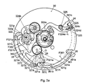
- This mechanism is part of a movement which comprises, in a conventional manner and not visible in the drawing, a source of energy such as a barrel, a time base such as a sprung balance, a work train, of which only a mobile 29 is visible on the figure 2a , and an escapement connecting the work train to the pendulum for maintenance, as well as time setting and chronograph mechanisms.
- the various components of the movement are arranged on a frame 30, formed of a plate and bridges, which ensures the relative positioning of the various moving parts.
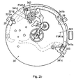
- the chronograph mechanism represented on the Figures 2a and 2b which is described in detail in the patent application EP 02022505.8 , allows the display of the minutes of timed time and the current time with the single needle 16.
- the part of the mechanism relating to the commands "start-stop” and “zeroing” could be replaced without any other mechanism of existing chronograph.
- the mechanism shown in the drawing essentially comprises locking, control and zeroing devices, the parts of which are parts are identified by the first two digits of their reference beginning respectively with 32, 34 and 36.
- the springs that comprise this mechanism are schematically represented by arrows identified by the letter "F” followed by the number corresponding to the reference of the part on which it acts. The arrow is oriented approximately in the direction in which the spring exerts its force.
- the zeroing device 36 is formed in particular by a lever 361 and a hammer 362.
- the lever 361 is provided with a pin 361a arranged facing the pusher 26 and a groove 361b placed so that it can serve as a housing for the pin 321h when the finger 321d bears against a column of the 342.
- a spring F361 tends to push the lever 361 in support against the pusher.
- the hammer is also subjected to an elastic force by a spring F362 keeping it bearing against the wheel 322.
- the hammer 362 will not be described in more detail it is intended to cooperate with cams carried by the wheels of the chronograph wheel bearing needles, to zero them. Such devices are well known to those skilled in the art.
- the pusher 24 acts on the lever 341 via the stud 325, which bears against the folding 341c. Also, when the pad 325 is not interposed between the folding 341c and the pusher 24, a pressure on the latter is without effect.
- Pressing the pusher again 28 rotates the column wheel 322 so that the nose 324b is raised and the stud 325 moves away from the pusher 24, which becomes inactive again.
- the lever 361 tilts and releases the pin 321h.
- the body 321a tilts under the effect of the spring F321a, and with it the lever 321k.
- the pin 321m is again facing the pusher 28 which becomes active again. The movement of the body 321 releases, in addition, the hammer 362 which controls the zeroing of the minute hands of time timed.
- the chronograph mechanism By pressing on the pusher 28, the chronograph mechanism returns to its locked state and the minute hand 16 goes from zero to the display of the current time, as explained above.
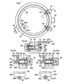
- the figure 3 represents a watch which can be seen the box 10, the setting ring 22 and two pushers 24 and 26.
- the figure 3a can also see the dial 12.
- the ring 22 is used to set the time information about the current time, the pusher 24 to control the start and stop of a chronograph mechanism, and the pusher 26 to zero.
- This watch is represented on the figure 3a cut according to a plane AA perpendicular to the drawing and on Figures 3b 1 and 3b 2 cut along a plane BB also perpendicular, in the locked position of the pusher 24 in 3b 1 and free in 3b 2 .
- the Figures 3c and 3d show, seen from the side as indicated by the arrows C and D, part of the watch respectively in the locked and free position of the pushers.
- chronograph mechanism is represented only schematically, by a portion of control lever 40 and zeroing lever 42, these portions cooperating respectively with the pushers 24 and 26.
- This mechanism can be of n ' any type controlled by two pushers.
- the box 10 carries, in addition, at 8 o'clock, a second ring 44, which, as can be seen on the figure 3a is secured to a rod 46 passing through the wall of the box 10.
- the rod 46 is provided with a pinion 48 mounted on a square 46a of the rod 46 and held by a screw 50 engaged in a thread formed in the rod 46 .
- the watch is, furthermore, equipped with a ring 52 disposed inside the box 10, adjacent to the inner wall of the caseband and the dial 12, which forms with the ring 44, the rod 46 and the pinion 48 , a locking device of the pushers 24 and 26.
- the ring 52 is provided, in its adjacent portion of the ring 44, a toothed gear sector 52a which meshes with the toothing of the pinion 48, thus allowing its driving in rotation, over a limited angle. As will be explained below, the ring 52 is intended to block the pushers 24 and 26.
- the Figures 3b 1 and 3b 2 represent the pusher 24 in section, engaged in the box 10, respectively in locked and free positions.
- a tube 54 driven into a hole which is provided with the box 10, serves as a housing for the pusher 24.
- the latter is formed of an outer button 24a, on which the user presses, and a rod 24b screwed on the button 24a and engaged in the tube 54.
- a seal 24c is housed on the rod 24b and bears against the inner end of the button 24a, while a coil spring 55 surrounds the rod 24b and is supported by a part in the bottom of the tube 54, on the other hand against the seal 24c ensuring the return of the pusher 24 when subjected to pressure.
- a washer may advantageously be interposed between the spring 55 and the seal 24c.
- the pusher 24 is held in the box 10 by means of a screw 56 engaged in a threaded hole in the rod 24b, which is not visible in the drawing.
- This screw is provided with a head 56a which cooperates with the lever 40 to control the chronograph mechanism.
- the head 56a has a groove 56b extending radially in its cylindrical portion.
- the ring 52 comprises a cylindrical portion 52b of inner and outer diameters and height such that this portion can be engaged in the groove 56b, as shown in FIG. figure 3c .
- the portion 52b is provided with a rounded cutout 52c, arranged so that, when aligned with the pusher 24, the groove is released, which makes possible the movement of the pusher 24.
- the cutout 52c is aligned on the axis B-B, so that the pusher 24 can be activated.
- the ring 52 is engaged in the groove 56b, thus blocking the pusher 24.
- the two extreme positions of the ring 52 can be defined by a jumper which has not been shown in the drawing, which would have the advantage of clearly marking these two positions.
- the ring 52 is provided with a display area 52c having two marks, for example of different colors 52d and 52e, which appear on the screen. one or the other in a window 12a of the dial 12, thus showing which position occupies the ring 52 and, in this way, whether the mechanism is in function or locked.
- the ring 52 is made of elastic material, for example steel or beryllium bronze. It also comprises a cylindrical portion 52b, but in which are cut lamellae 52f, integral with the cylindrical portion at one of their ends, free and forming, by folding, a finger 52g at the other end. This finger 52g is at the same level as the screw head 56a. In this way, if the blade 52f is opposite the screw head 56a, an action on the pusher 24 causes the screw head 56a to bear against the blade 52f, the finger 52g pushing the lever 40. In the vicinity of the folding 52g, the cylindrical portion is interrupted, so that by rotating the ring to bring it to its second position, the blade is no longer opposite the screw head 56a, the displacement of the pusher 24 then taking place in a vacuum.
- control member could also be provided by the time setting ring 22 in its depressed position, especially in the case where the movement comprises a quartz time base and a source of electrical energy.
Landscapes
- Physics & Mathematics (AREA)
- General Physics & Mathematics (AREA)
- Measurement Of Unknown Time Intervals (AREA)
- Electric Clocks (AREA)
- Electromechanical Clocks (AREA)
Abstract
Description
La présente invention concerne les montres de type chronographes. De telles montres permettent de mesurer un temps à partir d'un instant donné, la commande étant effectuée par une pression sur un ou des poussoirs. Elle se rapporte plus précisément à une montre munie d'un mouvement comprenant :
- ■ des moyens d'affichage du temps courant,
- ■ des moyens d'affichage d'un temps chronométré,
- ■ une base de temps agencée pour réguler les moyens d'affichage, aussi bien de temps courant que de temps chronométré,
- ■ un dispositif de commande assurant le départ et l'arrêt des moyens d'affichage du temps chronométré, et
- ■ un dispositif de mise à zéro pour ramener à zéro les moyens d'affichage de temps chronométré lorsqu'une mesure est terminée.
- ■ display means of the current time,
- ■ display means of a timed time,
- A time base arranged to regulate the display means, both current time and timed time,
- A control device for starting and stopping the means for displaying the timed time, and
- A reset device for zeroing the timed display means when a measurement is completed.
Cette montre comprend, en outre, une boîte servant de logement au mouvement et comportant au moins un poussoir destiné à commander les dispositifs de commande et de mise à zéro. Certaines de ces montres ne comportent qu'un poussoir commandant les deux dispositifs, d'autres, plus fréquentes, comprennent deux poussoirs distincts.This watch further comprises a housing housing for movement and having at least one pusher for controlling the control devices and zeroing. Some of these watches have only one pushbutton controlling the two devices, others, more frequent, include two separate pushers.
De telles montres sont susceptibles de manoeuvres intempestives. Ainsi, un choc sur l'un des poussoirs peut provoquer l'arrêt inopiné d'une mesure en cours. Une telle situation peut aussi se produire en plongée, où la pression de l'eau agit sur le poussoir départ-arrêt jusqu'à pouvoir interrompre une mesure en cours, ce qui peut être, pour le moins, préjudiciable.Such watches are susceptible to untimely maneuvers. Thus, a shock on one of the pushers can cause the unexpected stop of a measurement in progress. Such a situation can also occur in diving, where the pressure of the water acts on the start-stop pushbutton until it can interrupt a measurement in progress, which can be, to say the least, detrimental.
Par ailleurs, il est possible de réaliser des montres qui comportent une même aiguille susceptible d'afficher plusieurs informations, comme par exemple les minutes de temps courant et les minutes de temps chronométré. L'une d'elles est décrite dans la demande de brevet
Le document
La présente invention, définie par la revendication 1, a pour but de pallier ces inconvénients. A cet effet, la montre selon l'invention est caractérisée en ce qu'elle comprend, en outre, un dispositif de verrouillage, agencé pour coopérer avec le dispositif de commande, et susceptible d'occuper des première et deuxième positions dans lesquelles le dispositif de commande peut être activé ou non, et un organe d'actionnement destiné à être accessible de l'extérieur de la boîte pour commander le dispositif de verrouillage. Grâce à ce dispositif de verrouillage, il est ainsi possible d'empêcher toute manipulation accidentelle.The present invention, defined by claim 1, is intended to overcome these disadvantages. To this end, the watch of the invention is characterized in that it further comprises a locking device arranged to cooperate with the control device, and capable of occupying first and second positions in which the device control may or may not be activated, and an actuating member intended to be accessible from the outside of the box for controlling the locking device. Thanks to this locking device, it is thus possible to prevent any accidental manipulation.
On connaît, certes, des montres de type chronographe dans lesquelles les poussoirs peuvent être vissés sur la carrure, de manière à améliorer l'étanchéité. Il est bien clair qu'un poussoir vissé devient inopérant. Une telle opération nécessite toutefois une certaine attention, chaque poussoir devant être verrouillé par lui-même. En disposant d'un organe de commande accessible de l'extérieur de la boîte, qui commande le dispositif de verrouillage, il est possible d'assurer un verrouillage des deux poussoirs simultanément. L'organe de commande peut aussi bien être un poussoir qu'une couronne, selon le but recherché.Chronograph-type watches are of course known in which the pushers can be screwed to the middle of the case so as to improve the seal. It is clear that a screwed pusher becomes inoperative. Such an operation, however, requires some attention, each pusher to be locked by itself. By having a control member accessible from the outside of the box, which controls the locking device, it is possible to ensure a locking of the two buttons simultaneously. The control member may as well be a pusher a crown, depending on the desired purpose.
Lorsque les moyens d'affichage de temps chronométrés permettent, en outre l'affichage d'une autre information, il est souhaitable que le dispositif de commande soit inactif tant que les moyens d'affichage de temps chronométrés affiche cette autre information. A cet effet, le dispositif de verrouillage est agencé de manière à ne pouvoir agir sur le dispositif de commande que lorsque les moyens d'affichage de temps chronométré sont à zéro ou affichent une information autre que le temps chronométré. De la sorte, tant que les moyens d'affichage de temps chronométrés affichent une autre information que le temps chronométré, une action sur l'organe de commande, et par lui sur le dispositif de verrouillage, rend le dispositif de commande actionnable et amène à zéro l'aiguille assurant un double affichage. Dans ce cas, l'organe de commande est avantageusement un poussoir.When the timed time display means further allows the display of other information, it is desirable that the controller be inactive as long as the timed time display means displays this other information. For this purpose, the locking device is arranged so as to be able to act on the control device only when the timed time display means are at zero or display information other than the timed time. Of the so that, as long as the time display means display other information than the timed time, an action on the control member, and by it on the locking device, makes the control device operable and leads to zero needle providing a dual display. In this case, the control member is advantageously a pusher.
Lors de certaines mesures, il est souhaitable de pouvoir conserver l'information jusqu'au moment où elle peut être notée ou utilisée. Pour permettre la sauvegarde des informations, le dispositif de verrouillage est agencé de manière à rendre également actionnable ou non le dispositif de mise à zéro.In some measurements, it is desirable to be able to store the information until it can be noted or used. In order to save the information, the locking device is arranged so as to make the zeroing device also actuable or not.
Le dispositif de verrouillage comprend avantageusement une pièce de blocage qui agit sur le poussoir pour l'immobiliser. De la sorte, le poussoir ne peut être déplacé accidentellement, ni par un mouvement de l'utilisateur, ni par la pression de l'eau en cours de plongée.The locking device advantageously comprises a locking piece which acts on the pusher to immobilize it. In this way, the pusher can not be moved accidentally, neither by a movement of the user, nor by the pressure of the water during dive.
En variante, le dispositif de verrouillage comprend une pièce de liaison mobile disposée de manière à ce que, selon la position qu'elle occupe, une pression sur le poussoir soit ou non transmise au mécanisme de commande.Alternatively, the locking device comprises a movable connecting piece arranged so that, depending on the position it occupies, a pressure on the pusher is or is not transmitted to the control mechanism.
Il est aussi possible de combiner la présence d'une pièce de liaison mobile avec un blocage du poussoir. Dans ce cas, lors de l'opération de blocage, le poussoir peut être déplacé, de manière à mettre son joint d'étanchéité sous contrainte et renforcer ainsi l'étanchéité.It is also possible to combine the presence of a movable connecting piece with a blocking of the pusher. In this case, during the blocking operation, the pusher can be moved, so as to put its seal under stress and thus strengthen the seal.
Afin de permettre à l'utilisateur de connaître l'état du mécanisme de chronographe, le dispositif de verrouillage comporte, en outre, un organe d'affichage apparent sur le cadran de la montre, permettant d'indiquer quelle position occupe le dispositif de verrouillage et, en conséquence, de savoir si le dispositif de commande est actionnable ou non.In order to allow the user to know the state of the chronograph mechanism, the locking device further comprises an apparent display member on the dial of the watch, to indicate which position occupies the locking device. and, consequently, whether the control device is operable or not.
L'organe d'actionnement peut être formé d'une couronne montée pivotante sur la boîte. Il peut aussi être formé d'un poussoir.The actuating member may be formed of a crown pivotally mounted on the box. It can also be formed of a pusher.
Dans un mode de réalisation particulièrement simple, le dispositif de verrouillage comprend :
- ■ une tige disposée au travers de la boîte et destinée à porter la couronne que comporte l'organe de commande, et un pignon à son extrémité intérieure à la boîte,
- ■ une bague entourant le mouvement et munie d'une denture sur une portion de sa tranche adjacente au pignon, et susceptible d'occuper deux positions, le passage de l'une à l'autre se faisant par un mouvement de rotation, et
- ■ un organe d'interposition, solidaire de la bague et coopérant avec le poussoir pour qu'il puisse agir ou non sur le dispositif de commande.
- A rod disposed through the box and intended to carry the crown that comprises the control member, and a pinion at its inner end to the box,
- A ring surrounding the movement and provided with a toothing on a portion of its portion adjacent to the pinion, and capable of occupying two positions, the passage from one to the other being effected by a rotational movement, and
- ■ an interposing member secured to the ring and cooperating with the pusher so that it may or may not act on the control device.
D'autres avantages et caractéristiques de l'invention ressortiront de la description qui va suivre, faite en regard du dessin annexé, dans lequel:
- ■ la
figure 1 représente une montre munie d'un mécanisme selon l'invention ; - ■ les
figures 2a , et2b illustrent un mécanisme de chronographe muni d'un organe de verrouillage de la seule fonction « départ-arrêt », équipant la montre de lafigure 1 ; - ■ les
figures 3 à 3d concernent un dispositif permettant de rendre inactifs, par blocage, les poussoirs «départ-arrêt» et « mise à zéro » ; - ■ les
figures 4 à 4d montrent un dispositif permettant de débrayer les poussoirs « départ-arrêt » et « mise à zéro », les rendant inopérants.
- ■ the
figure 1 represents a watch provided with a mechanism according to the invention; - ■ the
Figures 2a , and2b illustrate a chronograph mechanism provided with a locking member of the only function "start-stop", equipping the watch with thefigure 1 ; - ■ the
Figures 3 to 3d concern a device making it possible to inactivate, by blocking, the "start-stop" and "zeroing"pushbuttons; - ■ the
Figures 4 to 4d show a device for disengaging the push-buttons "start-stop" and "zeroing", making them inoperative.
La montre représentée sur la
L'affichage du temps courant est corrigé au moyen d'une couronne de mise à l'heure 22, reliée aux organes du mouvement par une tige de mise à l'heure non visible au dessin.The display of the current time is corrected by means of a
Les fonctions relatives au chronométrage sont assurées par trois poussoirs 24, 26 et 28 respectivement disposés à deux heures, quatre heures et huit heures. Le poussoir 24 commande le départ et l'arrêt d'une mesure de temps chronométré, alors que le poussoir 26 assure la mise à zéro des aiguilles 16 et 20 lorsqu'une mesure de temps chronométré a été interrompue. Enfin, le poussoir 28 permet de faire passer le mécanisme de chronographe d'un premier état, dans lequel il est verrouillé, dans un deuxième état dans lequel il est déverrouillé.The functions relating to the timing are provided by three
Lorsque le mécanisme de chronographe est verrouillé, l'aiguille 16 affiche les minutes de temps courant, alors que, lorsqu'il est déverrouillé, il indique le temps chronométré. A l'état verrouillé, les poussoirs 24 et 26 sont inactifs. Pour permettre le passage de l'un à l'autre de ces états, le mécanisme comprend un dispositif de verrouillage qui sera décrit de manière plus détaillée ci-après et qui a pour effet de rendre inopérant le poussoir 24 lorsque le mécanisme est verrouillé, alors que le poussoir 28 est hors fonction lorsqu'une mesure est en cours.When the chronograph mechanism is locked, the
Ce mécanisme fait partie d'un mouvement qui comporte, de manière classique et non visible au dessin, une source d'énergie telle qu'un barillet, une base de temps telle qu'un balancier-spiral, un rouage de finissage, dont seul un mobile 29 est visible sur la
Comme expliqué plus haut, le mécanisme de chronographe représenté sur les
Le mécanisme représenté au dessin comporte essentiellement des dispositifs de verrouillage, de commande et de mise à zéro, dont les pièces en faisant parties sont identifiées par les deux premiers chiffres de leur référence commençant respectivement par 32, 34 et 36. Les ressorts que comporte ce mécanisme sont schématiquement représentés par des flèches identifiées par la lettre « F » suivie du nombre correspondant à la référence de la pièce sur laquelle il agit. La flèche est orientée, de manière approximative, dans la direction selon laquelle le ressort exerce sa force.The mechanism shown in the drawing essentially comprises locking, control and zeroing devices, the parts of which are parts are identified by the first two digits of their reference beginning respectively with 32, 34 and 36. The springs that comprise this mechanism are schematically represented by arrows identified by the letter "F" followed by the number corresponding to the reference of the part on which it acts. The arrow is oriented approximately in the direction in which the spring exerts its force.
Le dispositif de verrouillage 32 comporte:
- un organe de commutation 321, comprenant :
- ■ un corps 321a en forme d'oiseau, avec une tête 321b munie d'un
trou 321c dans lequel est engagée une tige traversant le bâti 30 de part en part etportant un doigt 321d visible sur lafigure 2b , un bec 321e, deuxailes 321f et 321g,l'aile 321g étant munie d'une goupille 321h, etune queue 321j, la tête 321b étant disposée du côté du centre du mouvement et laqueue 321j à la périphérie, au voisinage de 7 heures, - ■
un levier 321k monté pivotant sur laqueue 321j et s'étendant sur le pourtour du mouvement de 7 à 9 heures,muni d'une goupille 321m disposée de manière à se trouver ou non sur le chemin parcouru par le poussoir 28, et d'une butée 321n placée à son extrémité libre, - ■
un cliquet 321p monté pivotant sur le levier 321k et limité dans son mouvement par la butée 321n,
- ■ un corps 321a en forme d'oiseau, avec une tête 321b munie d'un
- une came de commutation, par exemple une roue à colonnes 322, schématiquement représentée, commandée en rotation par le cliquet 321p, tournant sur le bâti 30 en 322a,
- un levier d'enclenchement 324, comportant un corps de forme allongée 324a, monté pivotant sur le bâti 30 dans sa partie médiane, et dont l'une des extrémités est munie d'un nez 324b agencé pour coopérer avec les colonnes de la roue 322, alors que l'autre extrémité comporte un premier trou
oblong 324c dans lequelun plot 325 est monté coulissant, destiné à coopérer avec le dispositif de commande 34, et un deuxième trou oblong 324d, dans lequel est logé une goupille à tête 326, elle-même fixée sur le bâti 30, assurant le positionnement du levier 324 dans le plan du mouvement.
- a switching member 321, comprising:
- A
body 321a in the shape of a bird, with ahead 321b provided with ahole 321c in which is engaged a rod passing through theframe 30 from one side and carrying afinger 321d visible on thefigure 2b , aspout 321e, twowings wing 321g being provided with apin 321h, and atail 321j, thehead 321b being disposed on the side of the center of the movement and thetail 321j at the periphery, in the vicinity of 7 hours, - A
lever 321k pivotally mounted on thetail 321j and extending around the periphery of the movement from 7 to 9 hours, provided with apin 321m arranged so as to be located or not on the path traveled by thepusher 28, and astop 321n placed at its free end, - A
ratchet 321p pivotally mounted on thelever 321k and limited in its movement by thestop 321n,
- A
- a switching cam, for example a
column wheel 322, diagrammatically represented, controlled in rotation by thepawl 321p, rotating on theframe 30 at 322a, - an engagement lever 324, comprising an
elongated body 324a, pivotally mounted on theframe 30 in its middle part, and one end of which is provided with anose 324b arranged to cooperate with the columns of thewheel 322 , while the other end has a firstoblong hole 324c in which apad 325 is slidably mounted, intended to cooperate with the control device 34, and a secondoblong hole 324d, in which is housed apin 326 head, it - Even fixed on theframe 30, ensuring the positioning of the lever 324 in the plane of movement.
Les pièces constitutives du dispositif de verrouillage 32 sont positionnées par des ressorts schématiquement représentés par une flèche, et plus particulièrement :
- le corps 321a par le ressort F321a,
- le levier 321k, par le ressort F321k qui tend à le ramener lorsqu'une pression a été appliquée sur le poussoir 28,
- le cliquet 321p par le ressort F321p qui le maintient en appui contre la goupille 321n,
- le corps 324a par le ressort F324a, qui tend à appliquer le nez 324b contre la roue 322, et
le plot 325 par le ressort F325 qui tend à l'appuyer du côté extérieur du trou oblong 324c.
- the
body 321a by the spring F321a, - the
lever 321k, by the spring F321k which tends to bring it back when a pressure has been applied to thepusher 28, - the
ratchet 321p by the spring F321p which keeps it bearing against thepin 321n, - the
body 324a by the spring F324a, which tends to apply thenose 324b against thewheel 322, and - the
stud 325 by the spring F325 which tends to press the outer side of theoblong hole 324c.
Le dispositif de commande 34, plus particulièrement visible sur la
- un levier de commande 341 comportant :
- ■ un corps 341a disposé à la périphérie du mouvement de 2 à 7 heures, qui pivote en 341b sur le bâti 30 légèrement en dessous de 4 heures, et qui est muni, à l'une de ses extrémités, d'un pliage 341c s'étendant dans l'épaisseur du
plot 325, et - ■
un cliquet 341d, monté pivotant sur l'autre extrémité du corps 341a, dont la fonction sera précisée ci-dessous,
- ■ un corps 341a disposé à la périphérie du mouvement de 2 à 7 heures, qui pivote en 341b sur le bâti 30 légèrement en dessous de 4 heures, et qui est muni, à l'une de ses extrémités, d'un pliage 341c s'étendant dans l'épaisseur du
- une came 342, par exemple de type roue à colonnes, entraînée par le cliquet 341d, qui commande l'embrayage de chronographe, non représenté au dessin, et positionne l'organe de commutation 321
par son doigt 321d.
- a
control lever 341 comprising:- A
body 341a disposed at the periphery of the movement of 2 to 7 hours, which pivots at 341b on theframe 30 slightly below 4 hours, and which is provided at one of its ends with afolding 341c s extending in the thickness of thepad 325, and - A
pawl 341d, pivotally mounted on the other end of thebody 341a, the function of which will be specified below,
- A
- a
cam 342, for example of column wheel type, driven by thepawl 341d, which controls the chronograph clutch, not shown in the drawing, and positions the switching member 321 by itsfinger 321d.
Les pièces constitutives du dispositif de commande 34 sont positionnées par des ressorts et plus particulièrement :
- le corps 341a, par le ressort F341a qui tend à le ramener lorsqu'une pression a été appliquée sur le poussoir 24, et
- le cliquet 341d, par le ressort F341d, qui l'applique contre la came 342.
- the
body 341a, by the spring F341a which tends to bring it back when pressure has been applied to thepusher 24, and - the
pawl 341d, by the spring F341d, which applies it against thecam 342.
Le dispositif de mise à zéro 36 est formé notamment d'un levier 361 et d'un marteau 362.The zeroing device 36 is formed in particular by a
Le levier 361 est muni d'une goupille 361a disposée en regard du poussoir 26 et d'une gorge 361b placée de manière à ce qu'elle puisse servir de logement à la goupille 321h lorsque le doigt 321d est en appui contre une colonne de la came 342. Un ressort F361 tend à repousser le levier 361 en appui contre le poussoir. Le marteau est également soumis à une force élastique par un ressort F362 le maintenant en appui contre la roue 322.The
Le marteau 362 ne sera pas décrit de manière plus détaillée il est destiné à coopérer avec des cames portées par les mobiles du rouage de chronographe portant des aiguilles, pour les mettre à zéro. De tels dispositifs sont bien connus de l'homme du métier.The
Dans le mécanisme ainsi décrit, le poussoir 24 agit sur le levier 341 par l'intermédiaire du plot 325, qui vient en appui contre le pliage 341c. Aussi, lorsque le plot 325 n'est pas interposé entre le pliage 341c et le poussoir 24, une pression sur ce dernier est sans effet.In the mechanism thus described, the
Lorsque le mécanisme de chronographe est verrouillé, le nez 324b est en appui contre une colonne de la came 322. Dans cette position, le plot 325 est en retrait du poussoir 24, lequel est donc inactif.When the chronograph mechanism is locked, the
Si l'utilisateur exerce une pression sur le poussoir 28, ce dernier vient pousser la goupille 321m, qui commande le levier 321k. Ce dernier entraîne le cliquet 321p qui fait tourner la roue à colonne 322.If the user exerts pressure on the
Une des colonnes de la roue 322 libère le nez 324b qui tombe entre deux colonnes sous l'effet du ressort F324a, de telle sorte que le plot 325 vient se placer entre le poussoir 24 et le pliage 341c.One of the columns of the
Une nouvelle pression sur le poussoir 28 fait tourner de un pas la roue à colonnes 322, de telle sorte que le nez 324 b est soulevé et le plot 325 s'écarte du poussoir 24, lequel redevient inactifPressing the pusher again 28 rotates the
Lorsque le poussoir 24 est actif, une pression sur ce dernier commande le démarrage d'une mesure, selon le fonctionnement habituel des mécanisme de chronographe et fait pivoter le levier 341 qui entraîne le cliquet 341d et, avec lui, la came 342. Le doigt 321d est soulevé par une colonne de la came 342. La goupille 321h s'engage alors dans le logement 361b. De plus, le levier 321k est entraîné par le corps 321a de telle sorte que la goupille 321m est décalée par rapport au poussoir 28. De la sorte, dès que le mécanisme de chronographe est enclenché, le poussoir 28 devient inactif Dans cet état, le poussoir 26 est aussi inactif. Certes le levier 361 pivote sous l'effet d'une pression sur le poussoir 26, mais ce mouvement n'a pas d'influence sur les autres pièces du mécanisme.When the
Une nouvelle pression sur le poussoir 24 arrête la mesure et fait tourner la came 342 de un pas. Le doigt 321d se trouve alors entre deux colonnes de cette came. Il ne tombe pas pour autant, malgré l'action du ressort F321a, à cause de la goupille 321h retenue dans le logement 361b. Le poussoir 28 reste donc inactif.Pressing the
Si le poussoir 24 fait l'objet d'une nouvelle pression, la mesure démarre à nouveau et le doigt 321d prend appui contre une colonne.If the
Si une pression est effectuée sur le poussoir 26 lorsque la mesure est interrompue, c'est à dire aussi lorsque le doigt 321d se trouve entre deux colonnes de la came 342, le levier 361 bascule et libère la goupille 321h. Le corps 321a bascule sous l'effet du ressort F321a, et avec lui le levier 321k. La goupille 321m se trouve de nouveau en regard du poussoir 28 qui redevient actif. Le mouvement du corps 321 libère, en outre, le marteau 362 qui commande la mise à zéro des aiguilles de minutes de temps chronométré.If a pressure is made on the
En pressant sur le poussoir 28, le mécanisme de chronographe retrouve son état verrouillé et l'aiguille des minutes 16 passe de zéro à l'affiche du temps courant, comme cela a été expliqué plus haut.By pressing on the
La
La couronne 22 sert à la mise à l'heure des informations relatives au temps courant, le poussoir 24 à la commande du départ et de l'arrêt d'un mécanisme de chronographe, et le poussoir 26 à sa mise à zéro. Cette montre est représentée sur la
Sur ces figures, le mécanisme de chronographe n'est représenté que schématiquement, par une portion de levier de commande 40 et de levier de mise à zéro 42, ces portions coopérant respectivement avec les poussoirs 24 et 26. Ce mécanisme peut être de n'importe quel type commandé par deux poussoirs.In these figures, the chronograph mechanism is represented only schematically, by a portion of
La boîte 10 porte, en outre, à 8 heures, une deuxième couronne 44, qui, comme on peut le voir sur la
La montre est, en outre, équipée d'une bague 52 disposée à l'intérieure de la boîte 10, adjacente à la paroi interne de la carrure et au cadran 12, qui forme avec la couronne 44, la tige 46 et le pignon 48, un dispositif de verrouillage des poussoirs 24 et 26.The watch is, furthermore, equipped with a
La bague 52 est munie, dans sa portion voisine de la couronne 44, d'un secteur de denture en chant 52a qui engrène avec la denture du pignon 48, permettant ainsi son entraînement en rotation, sur un angle limité. Comme cela sera expliqué plus loin, la bague 52 est destinée à bloquer les poussoirs 24 et 26.The
Les
Le poussoir 24 est maintenu dans la boîte 10 au moyen d'une vis 56 engagée dans un trou taraudé de la tige 24b, qui n'est pas visible au dessin. Cette vis est munie d'une tête 56a qui coopère avec le levier 40 pour commander le mécanisme de chronographe. La tête 56a présente une gorge 56b s'étendant radialement dans sa portion cylindrique.The
Pour assurer le blocage du poussoir 24, la bague 52 comprend une portion cylindrique 52b, de diamètres intérieur et extérieur et de hauteur tels que cette portion peut être engagée dans la gorge 56b, comme le montre la
La portion 52b est munie d'une découpe arrondie 52c, disposée de manière à ce que, lorsqu'elle est alignée sur le poussoir 24, la gorge soit libérée, ce qui rend le possible le mouvement du poussoir 24.The
Lorsque la bague 52 se trouve dans l'une de ses positions extrêmes, la découpe 52c est alignée sur l'axe B-B, de telle sorte que le poussoir 24 peut être activé. Dans l'autre position, la bague 52 est engagée dans la gorge 56b, bloquant ainsi le poussoir 24.When the
Le poussoir 26, qui présente une même structure que le poussoir 24 coopère avec la bague 52 de manière identique à ce dernier. Une description détaillée n'apporterait donc rien de plus à la compréhension du dispositif.The
De manière avantageuse, les deux positions extrêmes de la bague 52 peuvent être définies par un sautoir qui n'a pas été représenté au dessin, qui aurait pour avantage de bien marquer ces deux positions. De plus, afin de permettre à l'utilisateur de savoir si le mécanisme est ou non en fonction, la bague 52 est munie d'une zone d'affichage 52c comportant deux marques, par exemple de couleurs différentes 52d et 52e, qui apparaissent l'une ou l'autre dans une fenêtre 12a du cadran 12, montrant ainsi quelle position occupe la bague 52 et, de la sorte, si le mécanisme est en fonction ou verrouillé.Advantageously, the two extreme positions of the
La variante représentée aux
Dans cette variante, la bague 52 est réalisée en matériau élastique, par exemple en acier ou en bronze au béryllium. Elle comporte également une portion cylindrique 52b, mais dans laquelle sont découpées des lamelles 52f, solidaires de la portion cylindrique à l'une de leurs extrémités, libres et formant, par pliage, un doigt 52g à l'autre extrémité. Ce doigt 52g se trouve au même niveau que la tête de vis 56a. De la sorte, si la lamelle 52f se trouve en regard de la tête de vis 56a, une action sur le poussoir 24 amène la tête de vis 56a en appui contre la lamelle 52f, le doigt 52g poussant le levier 40. Au voisinage du pliage 52g, la portion cylindrique est interrompue, de telle sorte qu'en faisant tourner la bague pour l'amener dans sa seconde position, la lamelle n'est plus en regard de la tête de vis 56a, le déplacement du poussoir 24 s'effectuant alors dans le vide.In this variant, the
Les différents modes de réalisation décrits ci-dessus peuvent faire l'objet de nombreuses variantes. Il est ainsi possible d'équiper le dispositif de verrouillage de moyens permettant la mise sous contrainte des joints 24c, afin de renforcer l'étanchéité de la montre.The various embodiments described above can be the subject of numerous variants. It is thus possible to equip the locking device with means enabling the
La fonction de l'organe de commande pourrait également être assurée par la couronne de mise à l'heure 22 dans sa position enfoncée, spécialement dans le cas où le mouvement comporte une base de temps à quartz et une source d'énergie électrique.The function of the control member could also be provided by the
Ainsi grâce aux différents modes de réalisation du dispositif décrit ci-dessus, il est possible de proposer des montres de type chronographe offrant une plus grande sécurité de fonctionnement.Thus, thanks to the different embodiments of the device described above, it is possible to propose chronograph type watches offering greater operational safety.
Claims (9)
- A watch, of the chronograph type, provided with a movement (29) comprising:■ means for displaying the current time,■ means for displaying a measured time,■ a time base arranged in order to regulate said display means,■ a control device (34, 40) ensuring the start and stop of the measured time display means,■ a reset device to reset the measured time display means when a measurement is finished,and a case (10) serving as a housing for said movement (29) and comprising at least one push-piece (24) designed to control said devices, characterized in that said watch also comprises a locking device (32, 52) arranged in order to cooperate with the control device (34, 40) and capable of occupying first and second positions in which said control device (34, 40) can be activated or not, and an actuating organ (28, 44), designed to be accessible from the outside of the case (10), in order to
control the locking device (32, 52). - The watch according to claim 1, characterized in that said measured time display means also allow the display of information other than the measured time and in that said locking device (32) is arranged so as to act on the control device (34) only when the measured time display means are at zero or display information other than the measured time.
- The watch according to claim 1, characterized in that said locking device (52) is arranged so as to cooperate with the reset device (42) to make it capable or incapable of being actuated.
- The watch according to one of claims 1 to 3, characterized in that said locking device (52b) comprises a blocking part which acts on said push-piece (24, 26) to immobilize it.
- The watch according to one of claims 1 to 4, characterized in that said locking device (32, 52) comprises a mobile connecting piece (325, 52f) arranged such that, depending on the position it occupies, pressure on the push-piece (24, 26) is, or is not, transmitted to the control device (34, 40).
- The watch according to one of claims 1 to 5, characterized in that the locking device (52) also comprises a display organ (52c), making it possible to indicate whether or not the control device (52) can be actuated.
- The watch according to claim 1, characterized in that said actuating organ (44) is made up of a crown (44) mounted rotatingly on said case (10).
- The watch according to claim 7, characterized in that the actuating organ comprises an arbor (46) disposed through the case (10) and designed to support said crown (44) at its outer end, and a pinion (48) at its end inside the case (10), and in that the locking device comprises:■ a ring (52) surrounding said movement (29) and provided with a toothing (52a) on a portion of its edge adjacent to said pinion (48), capable of occupying two positions, the passage from one to the other being done by a rotational movement, and■ an interposition organ (52b, 52f), integral with the ring (52) and cooperating with the push-piece (24) so that it can act or not act on the control device (40).
- The watch according to claim 1, characterized in that said actuating organ is made up of a push-piece (28) mounted slidingly on said case (10).
Priority Applications (1)
| Application Number | Priority Date | Filing Date | Title |
|---|---|---|---|
| EP02785776A EP1550012B8 (en) | 2002-10-07 | 2002-12-02 | Chronograph-type watch |
Applications Claiming Priority (4)
| Application Number | Priority Date | Filing Date | Title |
|---|---|---|---|
| EP02022505A EP1408383B1 (en) | 2002-10-07 | 2002-10-07 | Chronograph movement |
| EP02022505 | 2002-10-07 | ||
| EP02785776A EP1550012B8 (en) | 2002-10-07 | 2002-12-02 | Chronograph-type watch |
| PCT/IB2002/005054 WO2004031290A2 (en) | 2002-10-07 | 2002-12-02 | Chronograph-type watch |
Publications (3)
| Publication Number | Publication Date |
|---|---|
| EP1550012A2 EP1550012A2 (en) | 2005-07-06 |
| EP1550012B1 true EP1550012B1 (en) | 2010-02-10 |
| EP1550012B8 EP1550012B8 (en) | 2010-05-19 |
Family
ID=69322564
Family Applications (1)
| Application Number | Title | Priority Date | Filing Date |
|---|---|---|---|
| EP02785776A Expired - Lifetime EP1550012B8 (en) | 2002-10-07 | 2002-12-02 | Chronograph-type watch |
Country Status (7)
| Country | Link |
|---|---|
| US (1) | US7232254B2 (en) |
| EP (1) | EP1550012B8 (en) |
| JP (1) | JP4370252B2 (en) |
| AT (1) | ATE457480T1 (en) |
| AU (1) | AU2002351064A1 (en) |
| DE (1) | DE60235328D1 (en) |
| WO (1) | WO2004031290A2 (en) |
Families Citing this family (10)
| Publication number | Priority date | Publication date | Assignee | Title |
|---|---|---|---|---|
| ATE316663T1 (en) * | 2002-10-07 | 2006-02-15 | Vaucher Mft Fleurier Sa | CHRONOGRAPH MOVEMENT |
| JP4304199B2 (en) * | 2006-09-26 | 2009-07-29 | セイコープレシジョン株式会社 | Timekeeping device, timekeeping system, and time measuring method |
| EP1959317B1 (en) * | 2007-02-14 | 2010-04-28 | Maurice Lacroix SA | Switching transmission mechanism |
| NL1037424C2 (en) | 2009-10-29 | 2011-05-02 | Atte Nicolaas Bakker | CHRONOGRAPH. |
| JP5536623B2 (en) * | 2010-02-03 | 2014-07-02 | セイコーインスツル株式会社 | Chronograph clock |
| JP2011247873A (en) * | 2010-04-30 | 2011-12-08 | Seiko Instruments Inc | Chronograph watch |
| WO2013033666A1 (en) * | 2011-09-01 | 2013-03-07 | Stefan Johansson | Timepiece case with integrated pusher and crown |
| JP5926566B2 (en) * | 2012-01-31 | 2016-05-25 | シチズンホールディングス株式会社 | Multi-function watch movement and multi-function watch |
| JP6121023B2 (en) * | 2016-04-22 | 2017-04-26 | シチズン時計株式会社 | Multi-function watch movement and multi-function watch |
| EP4202570B1 (en) * | 2021-12-23 | 2024-07-03 | Montres Breguet S.A. | Timepiece movement including a stop second function operable from two separate control members |
Family Cites Families (8)
| Publication number | Priority date | Publication date | Assignee | Title |
|---|---|---|---|---|
| CH104374A (en) | 1923-05-07 | 1924-05-01 | Leon Breitling Montbrillant Wa | Time counter. |
| GB1405102A (en) | 1971-08-20 | 1975-09-03 | Smiths Industries Ltd | Stop watches |
| IT1285148B1 (en) * | 1996-06-03 | 1998-06-03 | Panerai Off Srl | DEVICE FOR LOCKING THE ROTATING BEZEL OF WATCHES, IN PARTICULAR DIVING WATCHES, AND FOR WATER-SEALING THE CROWN |
| JP2899967B1 (en) | 1998-01-07 | 1999-06-02 | セイコーインスツルメンツ株式会社 | Start / stop lever spring for chronograph watches |
| EP0996043B1 (en) * | 1998-04-21 | 2009-03-11 | Seiko Epson Corporation | Time measuring device |
| EP1048988A3 (en) * | 1999-04-27 | 2001-05-16 | Alain Mouawad | Locking device for a watch winding button |
| JP4959082B2 (en) * | 1999-10-14 | 2012-06-20 | シチズンホールディングス株式会社 | Electronic timepiece and driving method of electronic timepiece |
| US6975561B2 (en) * | 2002-06-13 | 2005-12-13 | Vaucher Manufacture Fleurier S.A. | Chronograph mechanism |
-
2002
- 2002-12-02 DE DE60235328T patent/DE60235328D1/en not_active Expired - Lifetime
- 2002-12-02 AT AT02785776T patent/ATE457480T1/en active
- 2002-12-02 WO PCT/IB2002/005054 patent/WO2004031290A2/en active Application Filing
- 2002-12-02 AU AU2002351064A patent/AU2002351064A1/en not_active Abandoned
- 2002-12-02 US US10/528,299 patent/US7232254B2/en not_active Expired - Fee Related
- 2002-12-02 EP EP02785776A patent/EP1550012B8/en not_active Expired - Lifetime
- 2002-12-02 JP JP2004541013A patent/JP4370252B2/en not_active Expired - Fee Related
Also Published As
| Publication number | Publication date |
|---|---|
| AU2002351064A8 (en) | 2004-04-23 |
| WO2004031290A2 (en) | 2004-04-15 |
| EP1550012A2 (en) | 2005-07-06 |
| DE60235328D1 (en) | 2010-03-25 |
| JP4370252B2 (en) | 2009-11-25 |
| EP1550012B8 (en) | 2010-05-19 |
| WO2004031290A3 (en) | 2004-07-22 |
| US7232254B2 (en) | 2007-06-19 |
| AU2002351064A1 (en) | 2004-04-23 |
| US20060164922A1 (en) | 2006-07-27 |
| ATE457480T1 (en) | 2010-02-15 |
| JP2006502383A (en) | 2006-01-19 |
Similar Documents
| Publication | Publication Date | Title |
|---|---|---|
| EP1408383B1 (en) | Chronograph movement | |
| EP2453322B1 (en) | Fast time quantity indicator corrector for a timepiece | |
| EP1777598B1 (en) | Timepiece with a mechanism to measure adjustable predetermined times | |
| EP0772104A1 (en) | Timepiece with a chronograph mechanism | |
| EP1840677B1 (en) | Return-to-zero of the seconds hand in a timepiece | |
| EP1550012B1 (en) | Chronograph-type watch | |
| EP2063326A2 (en) | Timepiece movement such as a split-seconds chronograph and timepiece equipped with such a movement | |
| WO2007115984A2 (en) | Timepiece comprising a dual time zone mechanism | |
| EP1394637A1 (en) | Timepiece, in particular wristwatch, comprising an alarm mechanism | |
| EP2561410A1 (en) | Chronograph mechanism, clockwork movement and timepiece comprising such a mechanism | |
| CH703361A2 (en) | Movement clock having chronograph functions and account-a-down. | |
| EP1373990B1 (en) | Timepiece component comprising a mechanism for interlocking a time indicating function and simultaneous winding of a barrel spring | |
| EP2073079A2 (en) | Chronograph mechanism, timepiece movement and timepiece comprising such a mechanism | |
| EP2367074B1 (en) | Multifunctional corrector device and timepiece comprising such a corrector device | |
| EP1372117B1 (en) | Mechanism for chronograph | |
| CH705056B1 (en) | Timepiece including a chronograph mechanism. | |
| EP1550013B1 (en) | Display device for watch | |
| EP1459138B1 (en) | Timepiece having a non-circular movement provided with a chronograph | |
| EP1461667B1 (en) | Mechanically driven timepiece associated with a chronograph | |
| EP1475682B1 (en) | Chronograph watch with immediate display of the fractions of a second | |
| CH527462A (en) | Chronograph watch | |
| EP1366471B1 (en) | Mechanical watch equipped with weekly cycle indicator | |
| EP3913443A1 (en) | Control device for clock mechanisms | |
| WO1999026115A1 (en) | Watch with quick correction using a push-piece | |
| CH716150B1 (en) | Watchmaker's mechanism for blocking a jumping mobile and movement for a chronograph watch including it. |
Legal Events
| Date | Code | Title | Description |
|---|---|---|---|
| PUAI | Public reference made under article 153(3) epc to a published international application that has entered the european phase |
Free format text: ORIGINAL CODE: 0009012 |
|
| 17P | Request for examination filed |
Effective date: 20050311 |
|
| AK | Designated contracting states |
Kind code of ref document: A2 Designated state(s): AT BE BG CH CY CZ DE DK EE ES FI FR GB GR IE IT LI LU MC NL PT SE SI SK TR |
|
| AX | Request for extension of the european patent |
Extension state: AL LT LV MK RO |
|
| DAX | Request for extension of the european patent (deleted) | ||
| RIN1 | Information on inventor provided before grant (corrected) |
Inventor name: FORSEY, STEPHEN, EDWARD, METHUEN Inventor name: GREUBEL, ROBERT |
|
| RAP1 | Party data changed (applicant data changed or rights of an application transferred) |
Owner name: VAUCHER MANUFACTURE FLEURIER SA Owner name: COMPLITIME SA |
|
| GRAP | Despatch of communication of intention to grant a patent |
Free format text: ORIGINAL CODE: EPIDOSNIGR1 |
|
| GRAS | Grant fee paid |
Free format text: ORIGINAL CODE: EPIDOSNIGR3 |
|
| GRAA | (expected) grant |
Free format text: ORIGINAL CODE: 0009210 |
|
| RAP1 | Party data changed (applicant data changed or rights of an application transferred) |
Owner name: COMPLITIME SA Owner name: VAUCHER MANUFACTURE FLEURIER SA |
|
| AK | Designated contracting states |
Kind code of ref document: B1 Designated state(s): AT BE BG CH CY CZ DE DK EE ES FI FR GB GR IE IT LI LU MC NL PT SE SI SK TR |
|
| REG | Reference to a national code |
Ref country code: GB Ref legal event code: FG4D Free format text: NOT ENGLISH |
|
| REG | Reference to a national code |
Ref country code: CH Ref legal event code: EP |
|
| REG | Reference to a national code |
Ref country code: IE Ref legal event code: FG4D |
|
| RIN2 | Information on inventor provided after grant (corrected) |
Inventor name: GREUBEL, ROBERT Inventor name: FORSEY, STEPHEN, EDWARD, METHUEN |
|
| REF | Corresponds to: |
Ref document number: 60235328 Country of ref document: DE Date of ref document: 20100325 Kind code of ref document: P |
|
| RAP2 | Party data changed (patent owner data changed or rights of a patent transferred) |
Owner name: COMPLITIME SA |
|
| REG | Reference to a national code |
Ref country code: CH Ref legal event code: NV Representative=s name: GLN S.A. |
|
| REG | Reference to a national code |
Ref country code: NL Ref legal event code: VDEP Effective date: 20100210 |
|
| PG25 | Lapsed in a contracting state [announced via postgrant information from national office to epo] |
Ref country code: PT Free format text: LAPSE BECAUSE OF FAILURE TO SUBMIT A TRANSLATION OF THE DESCRIPTION OR TO PAY THE FEE WITHIN THE PRESCRIBED TIME-LIMIT Effective date: 20100611 Ref country code: ES Free format text: LAPSE BECAUSE OF FAILURE TO SUBMIT A TRANSLATION OF THE DESCRIPTION OR TO PAY THE FEE WITHIN THE PRESCRIBED TIME-LIMIT Effective date: 20100521 |
|
| PG25 | Lapsed in a contracting state [announced via postgrant information from national office to epo] |
Ref country code: FI Free format text: LAPSE BECAUSE OF FAILURE TO SUBMIT A TRANSLATION OF THE DESCRIPTION OR TO PAY THE FEE WITHIN THE PRESCRIBED TIME-LIMIT Effective date: 20100210 Ref country code: SI Free format text: LAPSE BECAUSE OF FAILURE TO SUBMIT A TRANSLATION OF THE DESCRIPTION OR TO PAY THE FEE WITHIN THE PRESCRIBED TIME-LIMIT Effective date: 20100210 |
|
| REG | Reference to a national code |
Ref country code: IE Ref legal event code: FD4D |
|
| PG25 | Lapsed in a contracting state [announced via postgrant information from national office to epo] |
Ref country code: NL Free format text: LAPSE BECAUSE OF FAILURE TO SUBMIT A TRANSLATION OF THE DESCRIPTION OR TO PAY THE FEE WITHIN THE PRESCRIBED TIME-LIMIT Effective date: 20100210 Ref country code: IE Free format text: LAPSE BECAUSE OF FAILURE TO SUBMIT A TRANSLATION OF THE DESCRIPTION OR TO PAY THE FEE WITHIN THE PRESCRIBED TIME-LIMIT Effective date: 20100210 Ref country code: GR Free format text: LAPSE BECAUSE OF FAILURE TO SUBMIT A TRANSLATION OF THE DESCRIPTION OR TO PAY THE FEE WITHIN THE PRESCRIBED TIME-LIMIT Effective date: 20100511 Ref country code: EE Free format text: LAPSE BECAUSE OF FAILURE TO SUBMIT A TRANSLATION OF THE DESCRIPTION OR TO PAY THE FEE WITHIN THE PRESCRIBED TIME-LIMIT Effective date: 20100210 Ref country code: CY Free format text: LAPSE BECAUSE OF FAILURE TO SUBMIT A TRANSLATION OF THE DESCRIPTION OR TO PAY THE FEE WITHIN THE PRESCRIBED TIME-LIMIT Effective date: 20100210 Ref country code: SE Free format text: LAPSE BECAUSE OF FAILURE TO SUBMIT A TRANSLATION OF THE DESCRIPTION OR TO PAY THE FEE WITHIN THE PRESCRIBED TIME-LIMIT Effective date: 20100210 |
|
| PG25 | Lapsed in a contracting state [announced via postgrant information from national office to epo] |
Ref country code: BG Free format text: LAPSE BECAUSE OF FAILURE TO SUBMIT A TRANSLATION OF THE DESCRIPTION OR TO PAY THE FEE WITHIN THE PRESCRIBED TIME-LIMIT Effective date: 20100510 Ref country code: SK Free format text: LAPSE BECAUSE OF FAILURE TO SUBMIT A TRANSLATION OF THE DESCRIPTION OR TO PAY THE FEE WITHIN THE PRESCRIBED TIME-LIMIT Effective date: 20100210 Ref country code: CZ Free format text: LAPSE BECAUSE OF FAILURE TO SUBMIT A TRANSLATION OF THE DESCRIPTION OR TO PAY THE FEE WITHIN THE PRESCRIBED TIME-LIMIT Effective date: 20100210 |
|
| PLBE | No opposition filed within time limit |
Free format text: ORIGINAL CODE: 0009261 |
|
| STAA | Information on the status of an ep patent application or granted ep patent |
Free format text: STATUS: NO OPPOSITION FILED WITHIN TIME LIMIT |
|
| 26N | No opposition filed |
Effective date: 20101111 |
|
| PG25 | Lapsed in a contracting state [announced via postgrant information from national office to epo] |
Ref country code: DK Free format text: LAPSE BECAUSE OF FAILURE TO SUBMIT A TRANSLATION OF THE DESCRIPTION OR TO PAY THE FEE WITHIN THE PRESCRIBED TIME-LIMIT Effective date: 20100210 |
|
| PGFP | Annual fee paid to national office [announced via postgrant information from national office to epo] |
Ref country code: AT Payment date: 20101119 Year of fee payment: 9 |
|
| PGFP | Annual fee paid to national office [announced via postgrant information from national office to epo] |
Ref country code: GB Payment date: 20101229 Year of fee payment: 9 Ref country code: IT Payment date: 20101223 Year of fee payment: 9 |
|
| BERE | Be: lapsed |
Owner name: COMPLITIME S.A. Effective date: 20101231 |
|
| PG25 | Lapsed in a contracting state [announced via postgrant information from national office to epo] |
Ref country code: MC Free format text: LAPSE BECAUSE OF NON-PAYMENT OF DUE FEES Effective date: 20101231 |
|
| PG25 | Lapsed in a contracting state [announced via postgrant information from national office to epo] |
Ref country code: BE Free format text: LAPSE BECAUSE OF NON-PAYMENT OF DUE FEES Effective date: 20101231 |
|
| PGFP | Annual fee paid to national office [announced via postgrant information from national office to epo] |
Ref country code: FR Payment date: 20120104 Year of fee payment: 10 |
|
| PG25 | Lapsed in a contracting state [announced via postgrant information from national office to epo] |
Ref country code: LU Free format text: LAPSE BECAUSE OF NON-PAYMENT OF DUE FEES Effective date: 20101202 |
|
| PG25 | Lapsed in a contracting state [announced via postgrant information from national office to epo] |
Ref country code: TR Free format text: LAPSE BECAUSE OF FAILURE TO SUBMIT A TRANSLATION OF THE DESCRIPTION OR TO PAY THE FEE WITHIN THE PRESCRIBED TIME-LIMIT Effective date: 20100210 |
|
| REG | Reference to a national code |
Ref country code: CH Ref legal event code: PCAR Free format text: NEW ADDRESS: AVENUE EDOUARD-DUBOIS 20, 2000 NEUCHATEL (CH) |
|
| REG | Reference to a national code |
Ref country code: AT Ref legal event code: MM01 Ref document number: 457480 Country of ref document: AT Kind code of ref document: T Effective date: 20121202 |
|
| GBPC | Gb: european patent ceased through non-payment of renewal fee |
Effective date: 20121202 |
|
| REG | Reference to a national code |
Ref country code: FR Ref legal event code: ST Effective date: 20130830 |
|
| PG25 | Lapsed in a contracting state [announced via postgrant information from national office to epo] |
Ref country code: AT Free format text: LAPSE BECAUSE OF NON-PAYMENT OF DUE FEES Effective date: 20121202 |
|
| PG25 | Lapsed in a contracting state [announced via postgrant information from national office to epo] |
Ref country code: FR Free format text: LAPSE BECAUSE OF NON-PAYMENT OF DUE FEES Effective date: 20130102 Ref country code: GB Free format text: LAPSE BECAUSE OF NON-PAYMENT OF DUE FEES Effective date: 20121202 |
|
| PG25 | Lapsed in a contracting state [announced via postgrant information from national office to epo] |
Ref country code: IT Free format text: LAPSE BECAUSE OF NON-PAYMENT OF DUE FEES Effective date: 20121202 |
|
| PGFP | Annual fee paid to national office [announced via postgrant information from national office to epo] |
Ref country code: DE Payment date: 20131230 Year of fee payment: 12 |
|
| REG | Reference to a national code |
Ref country code: DE Ref legal event code: R119 Ref document number: 60235328 Country of ref document: DE |
|
| PG25 | Lapsed in a contracting state [announced via postgrant information from national office to epo] |
Ref country code: DE Free format text: LAPSE BECAUSE OF NON-PAYMENT OF DUE FEES Effective date: 20150701 |
|
| REG | Reference to a national code |
Ref country code: CH Ref legal event code: NV Representative=s name: E-PATENT S.A., CH |
|
| PGFP | Annual fee paid to national office [announced via postgrant information from national office to epo] |
Ref country code: CH Payment date: 20220104 Year of fee payment: 20 |
|
| REG | Reference to a national code |
Ref country code: CH Ref legal event code: PL |