EP1549555B1 - Grossvolumiger behälter mit zwei behälterteilen und einer stützvorrichtung im verbindungsbereich - Google Patents
Grossvolumiger behälter mit zwei behälterteilen und einer stützvorrichtung im verbindungsbereich Download PDFInfo
- Publication number
- EP1549555B1 EP1549555B1 EP03797289A EP03797289A EP1549555B1 EP 1549555 B1 EP1549555 B1 EP 1549555B1 EP 03797289 A EP03797289 A EP 03797289A EP 03797289 A EP03797289 A EP 03797289A EP 1549555 B1 EP1549555 B1 EP 1549555B1
- Authority
- EP
- European Patent Office
- Prior art keywords
- container
- container according
- parts
- connecting frame
- support device
- Prior art date
- Legal status (The legal status is an assumption and is not a legal conclusion. Google has not performed a legal analysis and makes no representation as to the accuracy of the status listed.)
- Expired - Lifetime
Links
- 239000004033 plastic Substances 0.000 claims abstract description 7
- 229920003023 plastic Polymers 0.000 claims abstract description 7
- 238000003466 welding Methods 0.000 claims description 2
- 239000004698 Polyethylene Substances 0.000 claims 1
- -1 polyethylene Polymers 0.000 claims 1
- 229920000573 polyethylene Polymers 0.000 claims 1
- 230000002787 reinforcement Effects 0.000 claims 1
- 238000005192 partition Methods 0.000 description 14
- 239000011324 bead Substances 0.000 description 5
- 230000003014 reinforcing effect Effects 0.000 description 5
- 239000002689 soil Substances 0.000 description 4
- 239000003673 groundwater Substances 0.000 description 3
- 238000007664 blowing Methods 0.000 description 2
- 239000012530 fluid Substances 0.000 description 2
- 238000009434 installation Methods 0.000 description 2
- 239000007788 liquid Substances 0.000 description 2
- 238000000071 blow moulding Methods 0.000 description 1
- 230000001419 dependent effect Effects 0.000 description 1
- 238000011161 development Methods 0.000 description 1
- 230000018109 developmental process Effects 0.000 description 1
- 239000000945 filler Substances 0.000 description 1
- 229920001684 low density polyethylene Polymers 0.000 description 1
- 239000004702 low-density polyethylene Substances 0.000 description 1
- 239000000463 material Substances 0.000 description 1
- 239000000155 melt Substances 0.000 description 1
- 230000008018 melting Effects 0.000 description 1
- 238000002844 melting Methods 0.000 description 1
- 238000002360 preparation method Methods 0.000 description 1
- 238000000926 separation method Methods 0.000 description 1
- 239000002351 wastewater Substances 0.000 description 1
Images


Classifications
-
- B—PERFORMING OPERATIONS; TRANSPORTING
- B65—CONVEYING; PACKING; STORING; HANDLING THIN OR FILAMENTARY MATERIAL
- B65D—CONTAINERS FOR STORAGE OR TRANSPORT OF ARTICLES OR MATERIALS, e.g. BAGS, BARRELS, BOTTLES, BOXES, CANS, CARTONS, CRATES, DRUMS, JARS, TANKS, HOPPERS, FORWARDING CONTAINERS; ACCESSORIES, CLOSURES, OR FITTINGS THEREFOR; PACKAGING ELEMENTS; PACKAGES
- B65D88/00—Large containers
- B65D88/02—Large containers rigid
- B65D88/06—Large containers rigid cylindrical
-
- B—PERFORMING OPERATIONS; TRANSPORTING
- B65—CONVEYING; PACKING; STORING; HANDLING THIN OR FILAMENTARY MATERIAL
- B65D—CONTAINERS FOR STORAGE OR TRANSPORT OF ARTICLES OR MATERIALS, e.g. BAGS, BARRELS, BOTTLES, BOXES, CANS, CARTONS, CRATES, DRUMS, JARS, TANKS, HOPPERS, FORWARDING CONTAINERS; ACCESSORIES, CLOSURES, OR FITTINGS THEREFOR; PACKAGING ELEMENTS; PACKAGES
- B65D88/00—Large containers
- B65D88/005—Large containers of variable capacity, e.g. with movable or adjustable walls or wall parts, modular
-
- B—PERFORMING OPERATIONS; TRANSPORTING
- B65—CONVEYING; PACKING; STORING; HANDLING THIN OR FILAMENTARY MATERIAL
- B65D—CONTAINERS FOR STORAGE OR TRANSPORT OF ARTICLES OR MATERIALS, e.g. BAGS, BARRELS, BOTTLES, BOXES, CANS, CARTONS, CRATES, DRUMS, JARS, TANKS, HOPPERS, FORWARDING CONTAINERS; ACCESSORIES, CLOSURES, OR FITTINGS THEREFOR; PACKAGING ELEMENTS; PACKAGES
- B65D88/00—Large containers
- B65D88/02—Large containers rigid
- B65D88/022—Large containers rigid in multiple arrangement, e.g. stackable, nestable, connected or joined together side-by-side
- B65D88/027—Large containers rigid in multiple arrangement, e.g. stackable, nestable, connected or joined together side-by-side single containers connected to each other by additional means so as to form a cluster of containers, e.g. a battery of containers
-
- E—FIXED CONSTRUCTIONS
- E03—WATER SUPPLY; SEWERAGE
- E03B—INSTALLATIONS OR METHODS FOR OBTAINING, COLLECTING, OR DISTRIBUTING WATER
- E03B3/00—Methods or installations for obtaining or collecting drinking water or tap water
- E03B3/02—Methods or installations for obtaining or collecting drinking water or tap water from rain-water
- E03B3/03—Special vessels for collecting or storing rain-water for use in the household, e.g. water-butts
-
- E—FIXED CONSTRUCTIONS
- E03—WATER SUPPLY; SEWERAGE
- E03F—SEWERS; CESSPOOLS
- E03F11/00—Cesspools
-
- B—PERFORMING OPERATIONS; TRANSPORTING
- B65—CONVEYING; PACKING; STORING; HANDLING THIN OR FILAMENTARY MATERIAL
- B65D—CONTAINERS FOR STORAGE OR TRANSPORT OF ARTICLES OR MATERIALS, e.g. BAGS, BARRELS, BOTTLES, BOXES, CANS, CARTONS, CRATES, DRUMS, JARS, TANKS, HOPPERS, FORWARDING CONTAINERS; ACCESSORIES, CLOSURES, OR FITTINGS THEREFOR; PACKAGING ELEMENTS; PACKAGES
- B65D88/00—Large containers
- B65D88/76—Large containers for use underground
-
- Y—GENERAL TAGGING OF NEW TECHNOLOGICAL DEVELOPMENTS; GENERAL TAGGING OF CROSS-SECTIONAL TECHNOLOGIES SPANNING OVER SEVERAL SECTIONS OF THE IPC; TECHNICAL SUBJECTS COVERED BY FORMER USPC CROSS-REFERENCE ART COLLECTIONS [XRACs] AND DIGESTS
- Y02—TECHNOLOGIES OR APPLICATIONS FOR MITIGATION OR ADAPTATION AGAINST CLIMATE CHANGE
- Y02A—TECHNOLOGIES FOR ADAPTATION TO CLIMATE CHANGE
- Y02A20/00—Water conservation; Efficient water supply; Efficient water use
- Y02A20/108—Rainwater harvesting
Definitions
- the invention relates to a container made of plastic, which consists of two container parts which are interconnected in an opening region.
- Such a container is from the DE 201 05 030 U1 of the same applicant.
- the container described is used for storage of liquids and consists of at least two separately manufactured and largely identical container parts.
- Each container part includes an upper and a lower flow nozzle with an opening.
- the two container parts are connected to each other in the region of the upper flow nozzle and in the region of the lower flow nozzle.
- the container parts contain beads to increase the stability.
- Such a container can be used for receiving rainwater or wastewater and should be suitable for underground storage.
- Known containers have a spherical, cylindrical or cuboid geometry.
- a width which is narrow in relation to the length is generally chosen in order to withstand soil loads.
- the container height must be large, which requires a large installation depth.
- soil nature such as in stony soils or in the presence of groundwater, it is often necessary to keep the installation depth low.
- the container is composed of two container parts.
- the container parts can be produced with relatively small blow molds and transported well.
- Each container part has a single connection frame which contains the connection opening.
- at least one connection frame contains a support device which extends in the vertical direction. As a result, the entire container is supported in the region of the interconnected connection frame and increases the strength in this area.
- the container composed of the two container parts thus has a high dimensional stability and can absorb large earth loads and resist buoyancy forces in the groundwater.
- the respective connecting frame has a circular shape whose outer diameter corresponds approximately to the height of the container.
- the base of the container is approximately square. Accordingly, such a container can be easily embedded in the soil of an existing square plot area. The resulting increased burdens and buoyancy forces are intercepted by the support device.
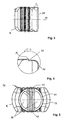
- FIG. 1 shows in a perspective view of an embodiment of the invention, in which a container 10 of two container parts 12, 14 is composed.
- the two container parts 12, 14 are made of plastic, for example, high molecular weight low-density polyethylene, and are made by blow molding.
- the first container part 12 includes a filling and emptying opening 16.
- both container parts 12, 14 are constructed the same, so that each container part 12, 14 can be made with the same blow mold. Only for the first container part 12 with a filler neck 18 (see. FIG. 2 ) a mold insert is then inserted into the blow mold.
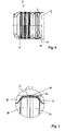
- FIG. 2 shows the container 10 in a side view, wherein the structure for the filling and emptying opening 16 is removed; to recognize is thus only one Inlet nozzle 18 in the topsoil 24 through which the entire container 10 can be filled and emptied.
- Each container part 12, 14 contains in its lateral surface beads 20, which serve to stiffen the outer shape of the container 10. These beads 20 are groove-like depressions, which are formed during plastic blowing in the lateral surface. The beads 20 increase the stiffness of the sheath body, so that the earth load and the buoyancy forces occurring by the groundwater is taken into account.
- the container parts 12, 14 are rounded at their edges and have in their lateral surface on the bottom 22 and the topsoil 24, the aforementioned beads 20.
- Each container part 12, 14 has a single connection frame 26 or 28, along which the two container parts 12, 14 are connected to each other.
- the container 10 typically has a square base of about 2.3 meters at a height of 1.35 meters.
- the inlet port 18 has a typical diameter of 0.7 m.
- FIG. 3 shows the container part 14, which is produced by plastic blowing.
- this preparation serving as a support device partition 30 is formed with, the structure in FIG. 4 as a section Z in the scale 1: 4 and in FIG. 5 can be seen in more detail in a view from direction H1.
- FIG. 4 shows that along the circumference of the shell of the container part 14, a raised edge 34 is formed. At the point 32, the partition wall 30 is then separated along the circumference.
- FIG. 5 shows a view from direction H1 in FIG. 3 ,
- the partition wall 30 includes in the middle region reinforcing ribs 36 and through holes 38 on both sides of the reinforcing ribs 36.
- an upper bore 40 and a lower bore 42 is provided to allow a fluid exchange in the region of the reinforcing ribs 36.
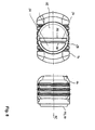
- FIG. 6 shows the container 10 in the assembled state as a side view.
- the container part 14 is assembled with the only partially visible container part 12, wherein the container part 14 belonging partition 30th and a partition part 44 belonging to the container part 12 face each other.
- the section Y is in the ratio 1: 4 in FIG. 7 shown in more detail as a cross section.
- the in the FIGS. 3, 4 and 5 shown partition 30 has been circumferentially separated at the point 32 and has been used in the resulting opening of the container part 14 after turning 180 °. The same thing happened to the container part 12 with the partition wall 44.
- the two container parts 12, 14 with their partitions 30, 44 face each other.
- the jacket body of the container parts 12, 14 and the associated partitions 44, 30 are connected to each other.
- the partitions 30, 44 contain the in FIG. 5 shown ribs 36 and form the support device for receiving vertical forces.
- the in the FIG. 2 illustrated connecting frame 28, 26 of the container parts 14, 12 are formed in this embodiment by the end faces of the open container parts 14, 12 and the end faces of the partition walls 30 and 44.
- FIGS. 8 to 12 show a further embodiment of the invention, in which the mutually facing connection frame 28, 26 of the container parts 12, 14 also include a support device. The same parts are still designated the same.
- FIG. 8 left is a front view of the connecting frame 28 is shown, which contains two sections 50, 52 as a connection opening.
- the left illustration is a view from direction H2 of the right side view.
- the connecting frame 28 includes in the vertical direction a supporting device 54 which includes projecting ribs 56, 58.
- FIG. 9 shows a representation of the two identical except for the topsoil container parts 14, 12 with associated connection frame 26, 28.
- the ribs 56, 58 of the container part 14 and the similar ribs 60, 62 of the container part 12 are arranged offset to one another and are in accordance with the Arrows P1, P2 moved towards each other.
- FIG. 10 shows the assembly of the container parts 14, 12.
- the cutouts W in FIG. 11 and X in FIG. 12 show details of the connection of the connection frame 26, 28.
- FIG. 11 It is shown that the opposing ribs 56, 60 are welded together in the vertical direction at the point 62. Another possibility is to screw or rivet the two ribs 56, 60 together. As in FIG. 11 can be seen, the ribs 56, 60 each protrude into the other container part, so that there are further advantages in terms of support function.
- FIG. 12 shows the in FIG. 10 designated cutout X.
- the container part 12 circumferential edge-shaped centering surface 66 abuts a formed on the container part 14 projecting abutment surface 68.
- the container width of a container part is chosen so that it is smaller than twice the diameter of the respective connecting frame.
Landscapes
- Engineering & Computer Science (AREA)
- Mechanical Engineering (AREA)
- Hydrology & Water Resources (AREA)
- Health & Medical Sciences (AREA)
- Public Health (AREA)
- Water Supply & Treatment (AREA)
- Life Sciences & Earth Sciences (AREA)
- Environmental & Geological Engineering (AREA)
- Rigid Containers With Two Or More Constituent Elements (AREA)
- Containers Having Bodies Formed In One Piece (AREA)
- Stackable Containers (AREA)
- Cooling, Air Intake And Gas Exhaust, And Fuel Tank Arrangements In Propulsion Units (AREA)
- Details Of Rigid Or Semi-Rigid Containers (AREA)
Abstract
Description
- Die Erfindung betrifft einen Behälter aus Kunststoff, der aus zwei Behälterteilen besteht, die in einem Öffnungsbereich miteinander verbunden sind.
- Ein derartiger Behälter ist aus der
DE 201 05 030 U1 desselben Anmelders bekannt. Der beschriebene Behälter dient zur Lagerung von Flüssigkeiten und besteht aus mindestens zwei getrennt gefertigten und weitgehend identischen Behälterteilen. Jeder Behälterteil enthält einen oberen und einen unteren Strömungsstutzen mit einer Öffnung. Die beiden Behälterteile werden im Bereich des oberen Strömungsstutzens und im Bereich des unteren Strömungsstutzens miteinander verbunden. Ferner enthalten die Behälterteile Sicken zur Erhöhung der Stabilität. - Ein derartiger Behälter kann zur Aufnahme von Regenwasser oder Abwasser verwendet werden und soll für die unterirdische Lagerung geeignet sein. Bekannte Behälter haben eine kugelförmige, zylindrische oder quaderförmige Geometrie. Bei quaderförmig gestalteten Behältern wird im allgemeinen eine im Verhältnis zur Länge geringe Breite gewählt, um Erdlasten zu widerstehen.
- Zum Erreichen eines großen Volumens muß dann die Behälterhöhe groß gewählt werden, was eine große Einbautiefe erfordert. Aus Gründen der Bodenbeschaffenheit, wie z.B. bei steinigen Böden oder bei Vorhandensein von Grundwasser, ist es häufig notwendig, die Einbautiefe gering zu halten.
- Es ist Aufgabe der Erfindung, einen Behälter aus Kunststoff anzugeben, der bei einem großen Aufnahmevolumen für den Einsatz in der Erde geeignet ist und eine hohe Stabilität hat.
- Diese Aufgabe wird durch die Merkmale des Anspruchs 1 gelöst. Vorteilhafte Weiterbildungen sind in den abhängigen Ansprüchen angegeben.
- Gemäß der Erfindung wird das bereits beschriebene Prinzip beibehalten, bei dem der Behälter aus zwei Behälterteilen zusammengesetzt wird. Auf diese Weise können die Behälterteile mit relativ kleinen Blasformen hergestellt werden und gut transportiert werden. Jeder Behälterteil hat einen einzigen Verbindungsrahmen, der die Verbindungsöffnung enthält wobei erfindungsgemäß mindestens ein Verbindungsrahmen eine Stützvorrichtung enthält, die sich in vertikaler Richtung erstreckt. Dadurch wird der gesamte Behälter im Bereich der miteinander verbundenen Verbindungsrahmen gestützt und in diesem Bereich die Festigkeit erhöht. Der aus den beiden Behälterteilen zusammengesetzte Behälter hat damit eine hohe Formfestigkeit und kann große Erdlasten aufnehmen sowie Auftriebskräften im Grundwasser widerstehen.
- Bei einem Ausführungsbeispiel hat der jeweilige Verbindungsrahmen eine Kreisform, dessen Außendurchmesser annähernd der Höhe des Behälters entspricht. Dadurch kann zwischen den beiden Behälterteilen eine große Öffnungsfläche für den Austausch von Flüssigkeit geschaffen werden. Weiterhin ist bei einem großen Durchmesser des Verbindungsrahmens die erforderliche Verbindung der beiden Behälterteile am Aufstellungsort, beispielsweise durch Verschweißen, einfacher auszuführen.
- Gemäß einem weiteren Ausführungsbeispiel ist die Grundfläche des Behälters in etwa quadratisch. Demgemäß kann ein solcher Behälter leicht in das Erdreich einer vorhandenen quadratischen Grundstücksfläche eingebettet werden. Die dabei auftretenden erhöhten Erdlasten und Auftriebskräfte werden durch die Stützvorrichtung abgefangen.
- Ausführungsbeispiele der Erfindung werden im folgenden anhand der Zeichnung erläutert. Darin zeigt:
- Figur 1
- eine perspektivische Ansicht eines ersten Ausführungsbeispiels der Erfindung,
- Figur 2
- den in
Figur 1 gezeigten Behälter in einer Seitenansicht, - Figur 3
- ein Behälterteil mit angeformter, noch nicht abgetrennter Trennwand,
- Figur 4
- ein Detail nach
Figur 3 , - Figur 5
- eine Ansicht der
Figur 3 aus Richtung H1, - Figur 6
- den Behälter im zusammengebauten Zustand als Seitenansicht,
- Figur 7
- einen Detailausschnitt aus
Figur 6 , - Figur 8
- Ansichten eines weiteren Ausführungsbeispiels der Erfindung,
- Figur 9
- die beiden Behälterteile vor dem Zusammenbau,
- Figur 10
- die zusammengebauten beiden Behälterteile,
- Figur 11
- ein Detail nach
Figur 10 , bei dem Rippen miteinander verschweißt werden, und - Figur 12
- ein Detail nach
Figur 10 , bei dem die Verbindungsrahmen umlaufend verschweißt werden. -
Figur 1 zeigt in einer perspektivischen Ansicht ein Ausführungsbeispiel der Erfindung, bei dem ein Behälter 10 aus zwei Behälterteilen 12, 14 zusammengesetzt ist. Die beiden Behälterteile 12, 14 bestehen aus Kunststoff, beispielsweise aus hochmolekularem Niederdruckpolyethylen, und sind im Blasformverfahren gefertigt. Der erste Behälterteil 12 enthält eine Füll- und Entleerungsöffnung 16. In den weiteren Teilen sind beide Behälterteile 12, 14 gleich aufgebaut, so daß jeder Behälterteil 12, 14 mit der gleichen Blasform hergestellt werden kann. Lediglich für den ersten Behälterteil 12 mit einem Einfüllstutzen 18 (vgl.Figur 2 ) wird in die Blasform dann ein Formeinsatz eingelegt. -
Figur 2 zeigt den Behälter 10 in einer Seitenansicht, wobei der Aufbau für die Füll- und Entleerungsöffnung 16 abmontiert ist; zu erkennen ist somit nur ein Einlassstutzen 18 im Oberboden 24, über den der gesamte Behälter 10 gefüllt und entleert werden kann. - Jeder Behälterteil 12, 14 enthält in seiner Mantelfläche Sicken 20, die der Versteifung der äußeren Form des Behälters 10 dienen. Diese Sicken 20 sind rinnenartige Vertiefungen, die beim Kunststoffblasen in der Mantelfläche ausgeformt werden. Die Sicken 20 erhöhen die Steifigkeit des Mantelkörpers, so daß der Erdlast und den durch das Grundwasser auftretenden Auftriebskräften Rechnung getragen wird. Die Behälterteile 12, 14 sind an ihren Kanten abgerundet und weisen in ihrer Mantelfläche auch am Unterboden 22 und am Oberboden 24 die erwähnten Sicken 20 auf.
- Jeder Behälterteil 12, 14 hat einen einzigen Verbindungsrahmen 26 bzw. 28, entlang dem die beiden Behälterteile 12, 14 miteinander verbunden sind.
- Typischerweise hat der Behälter 10 für ein nutzbares Volumen von 5000 Liter Flüssigkeit ein quadratisches Grundmaß von etwa 2,3 m bei einer Höhe von 1,35 m. Der Einlassstutzen 18 hat einen typischen Durchmesser von 0,7 m.
-
Figur 3 zeigt den Behälterteil 14, der im Kunststoffblasverfahren hergestellt wird. Bei dieser Herstellung wird eine als Stützvorrichtung dienende Trennwand 30 mit ausgeformt, deren Aufbau inFigur 4 als Ausschnitt Z im Maßstab 1:4 und inFigur 5 in einer Ansicht aus Richtung H1 genauer zu erkennen ist. -
Figur 4 zeigt, daß entlang dem Umfang des Mantels des Behälterteils 14 ein erhabener Rand 34 ausgebildet ist. An der Stelle 32 wird dann die Trennwand 30 entlang dem Umfang abgetrennt. -
Figur 5 zeigt eine Sicht aus Richtung H1 inFigur 3 . Die Trennwand 30 enthält im mittleren Bereich Verstärkungsrippen 36 und Durchgangsöffnungen 38 beidseitig der Verstärkungsrippen 36. Im Bereich der Verstärkungsrippen 36 ist eine obere Bohrung 40 und eine untere Bohrung 42 vorgesehen, um einen Flüssigkeitsaustausch im Bereich der Verstärkungsrippen 36 zu ermöglichen. -
Figur 6 zeigt den Behälter 10 im zusammengebauten Zustand als Seitenansicht. Das Behälterteil 14 ist mit dem nur teilweise zu sehenden Behälterteil 12 zusammengesetzt, wobei die zum Behälterteil 14 gehörende Trennwand 30 und eine zum Behälterteil 12 gehörende Trennwand 44 einander zugewandt sind. Der Ausschnitt Y ist im Verhältnis 1:4 inFigur 7 als Querschnitt näher dargestellt. Die in denFiguren 3, 4 und 5 dargestellte Trennwand 30 ist an der Stelle 32 umlaufend abgetrennt worden und in die so entstandene Öffnung des Behälterteils 14 nach Umdrehen um 180° eingesetzt worden. Ähnliches ist beim Behälterteil 12 mit der Trennwand 44 geschehen. Somit stehen sich die beiden Behälterteile 12, 14 mit ihren Trennwänden 30, 44 einander gegenüber. Im Bereich des erhabenen Randes 34 des Behälterteils 14 und eines entsprechenden erhabenen Randes 46 des Behälterteils 12 erfolgt eine umlaufende Verschweißung mit dem Schmelzgut 48, wobei gleichzeitig der Mantelkörper der Behälterteile 12, 14 sowie die zugehörigen Trennwände 44, 30 miteinander verbunden werden. Die Trennwände 30, 44 enthalten die inFigur 5 dargestellten Rippen 36 und bilden die Stützvorrichtung zur Aufnahme vertikaler Kräfte. Die in derFigur 2 dargestellten Verbindungsrahmen 28, 26 der Behälterteile 14, 12 werden bei diesem Ausführungsbeispiel durch die Stirnflächen der offenen Behälterteile 14, 12 und die Stirnflächen der Trennwände 30 und 44 gebildet. - Die
Figuren 8 bis 12 zeigen ein weiteres Ausführungsbeispiel der Erfindung, bei dem die einander zugewandten Verbindungsrahmen 28, 26 der Behälterteile 12, 14 ebenfalls eine Stützvorrichtung enthalten. Gleiche Teile sind weiterhin gleich bezeichnet. - In
Figur 8 ist links eine Vorderansicht auf den Verbindungsrahmen 28 gezeigt, der als Verbindungsöffnung zwei Abschnitte 50, 52 enthält. Die linke Darstellung ist eine Ansicht aus Richtung H2 der rechts dargestellten Seitenansicht. Der Verbindungsrahmen 28 enthält in vertikaler Richtung eine Stützvorrichtung 54, die vorstehende Rippen 56, 58 enthält. -
Figur 9 zeigt eine Darstellung mit den zwei bis auf die Oberböden identischen Behälterteilen 14, 12 mit zugehörigen Verbindungsrahmen 26, 28. Die Rippen 56, 58 des Behälterteils 14 und die gleichartigen Rippen 60, 62 des Behälterteils 12 sind zueinander versetzt angeordnet und werden beim Zusammenbau entsprechend den Pfeilen P1, P2 aufeinander zu bewegt. -
Figur 10 zeigt den Zusammenbau der Behälterteile 14, 12. Die Ausschnitte W inFigur 11 und X inFigur 12 zeigen Details der Verbindung der Verbindungsrahmen 26, 28. InFigur 11 ist dargestellt, daß die einander gegenüberstehenden Rippen 56, 60 in vertikaler Richtung miteinander an der Stelle 62 verschweiß werden. Eine andere Möglichkeit besteht darin, die beiden Rippen 56, 60 miteinander zu verschrauben oder zu vernieten. Wie inFigur 11 zu erkennen ist, ragen die Rippen 56, 60 jeweils in den anderen Behälterteil hinein, so daß sich weitere Vorteile im Hinblick auf die Stützfunktion ergeben. -
Figur 12 zeigt den inFigur 10 bezeichneten Ausschnitt X. Entlang der beiden Verbindungsrahmen der Behälterteile 12, 14 erfolgt eine Verschweißung mit dem Schweißgut 64, wobei ein am Behälterteil 12 ausgebildetes umlaufendes randförmiges Zentrierfläche 66 an einer am Behälterteil 14 ausgebildeten vorragenden Stoßfläche 68 anliegt. - Es können zahlreiche Varianten vorgesehen sein. Beispielsweise kann es ausreichen, nur einen Verbindungsrahmen mit einer Stützvorrichtung auszustatten. Weiterhin ist es möglich, daß die Behälterteile unterschiedliche Grundflächen haben.
- Vorzugsweise wird die Behälterbreite eines Behälterteils so gewählt, daß sie kleiner als der doppelte Durchmesser des jeweiligen Verbindungsrahmens ist.
-
- 10
- Behälter
- 12, 14
- Behälterteile
- 16
- Füll- und Entleeröffnung
- 18
- Einlassstutzen
- 20
- Sicken
- 22
- Unterboden
- 24
- Oberboden
- 26, 28
- Verbindungsrahmen
- 30
- als Stützvorrichtung dienende Trennwand
- 32
- Abtrennstelle
- 34
- erhabener Rand
- 36
- Verstärkungsrippen
- 38
- Durchgangsöffnungen
- 40
- obere Bohrung
- 42
- untere Bohrung
- 44
- als Stützvorrichtung dienende Trennwand
- 46
- erhabener Rand
- 48
- Schmelzgut
- 50,52
- Öffnungsabschnitte
- 54
- Stützvorrichtung
- 56, 58
- Rippen
- 60, 62
- Rippen
- P1, P2
- Richtungspfeile
- 64
- Schweißgut
- 66
- Zentrierfläche
- 68
- Stoßfläche
Claims (14)
- Behälter aus Kunststoff,
wobei der Behälter (10) aus zwei Behälterteilen (12, 14) besteht, die in einem Öffnungsbereich miteinander verbunden sind, wobei
jeder Behälterteil (12, 14) einen einzigen Verbindungsrahmen (26, 28) hat, der die Verbindungsöffnung enthält und wobei
die Behälterteile (12, 14) entlang der einander zugewandten Verbindungsrahmen (26, 28) verbindbar sind,
dadurch gekennzeichnet, daß mindestens ein Verbindungsrahmen (26, 28) eine Stützvorrichtung (30, 44, 54) enthält, die sich im Verbindungsrahmen (26, 28) in vertikaler Richtung erstreckt. - Behälter nach Anspruch 1, dadurch gekennzeichnet, daß beide Verbindungsrahmen (26, 28) eine Kreisform haben, deren Außendurchmesser annähemd der Höhe des Behälters (10) entspricht.
- Behälter nach Anspruch 1 oder 2, dadurch gekennzeichnet, daß die beiden Behälterteile (12, 14) mit Ausnahme eines Einlaßstutzens (18) einen im wesentlichen identischen Aufbau haben.
- Behälter nach einem der vorhergehenden Ansprüche, dadurch gekennzeichnet, daß die Stützvorrichtung (54) vertikal verlaufende Versteifungsrippen (56, 58, 60, 62) enthält.
- Behälter nach Anspruch 4, dadurch gekennzeichnet, daß die Versteifungsrippen (56, 58, 60, 62) aus der Ebene des Verbindungsrahmens (26, 28) hervorragen.
- Behälter nach Anspruch 4 oder 5, dadurch gekennzeichnet, daß die Versteifungsrippen (56, 58, 60, 62) an ihrem unteren und oberen Enden jeweils Zentrierflächen (66) haben, die mit gegenüberliegenden Stoßflächen (68) zusammenwirken.
- Behälter nach einem der vorhergehenden Ansprüche 4 bis 6, dadurch gekennzeichnet, daß einander gegenüberstehende Versteifungsrippen (56, 58, 60, 62) der beiden Behälterteile (12, 14) im Mittenbereich miteinander verbunden sind.
- Behälter nach einem der vorhergehenden Ansprüche 1 bis 3, dadurch gekennzeichnet, daß die Stützvorrichtung eine Wand (30, 44) enthält.
- Behälter nach Anspruch 8, dadurch gekennzeichnet, daß die Wand (30, 44) vertikal verlaufende Rippen (36) umfaßt.
- Behälter nach Anspruch 8, dadurch gekennzeichnet, daß die Wand (30, 44) einen zylinderförmigen Rand hat, der in den Verbindungsrahmen (26, 28) eingesetzt ist, und daß die Verbindungsrahmen (26, 28) der beiden Behälterteile (12, 14) miteinander verschweißt werden, wobei die Schweißnaht (48) auch den Rand der Wand (30, 44) mit den Verbindungsrahmen (26, 28) verschweißt.
- Behälter nach einem der vorhergehenden Ansprüche, dadurch gekennzeichnet, daß die Breite jedes Behälterteils (12, 14) kleiner als der doppelte Durchmesser des jeweiligen Verbindungsrahmens (26, 28) ist.
- Behälter nach einem der vorhergehenden Ansprüche, dadurch gekennzeichnet, daß er aus hochmolekularem Niederdruckpolyethylen besteht.
- Behälter nach einem der vorhergehenden Ansprüche, dadurch gekennzeichnet, daß er ein Fassungsvolumen von 4000 bis 6000 Liter hat.
- Behälter nach einem der vorhergehenden Ansprüche, dadurch gekennzeichnet, daß er etwa eine quadratische Grundfläche hat.
Priority Applications (1)
| Application Number | Priority Date | Filing Date | Title |
|---|---|---|---|
| SI200332214T SI1549555T1 (sl) | 2002-09-12 | 2003-09-10 | Velikoprostorninski vsebnik z dvema deloma vsebnika in z oporno pripravo v območju povezave |
Applications Claiming Priority (3)
| Application Number | Priority Date | Filing Date | Title |
|---|---|---|---|
| DE10242387A DE10242387A1 (de) | 2002-09-12 | 2002-09-12 | Großvolumiger Behälter mit zwei Behälterteilen und einer Stützvorrichtung im Verbindungsbereich |
| DE10242387 | 2002-09-12 | ||
| PCT/EP2003/010044 WO2004026711A1 (de) | 2002-09-12 | 2003-09-10 | Grossvolumiger behälter mit zwei behälterteilen und einer stützvorrichtung im verbindungsbereich |
Publications (2)
| Publication Number | Publication Date |
|---|---|
| EP1549555A1 EP1549555A1 (de) | 2005-07-06 |
| EP1549555B1 true EP1549555B1 (de) | 2012-08-22 |
Family
ID=31969099
Family Applications (1)
| Application Number | Title | Priority Date | Filing Date |
|---|---|---|---|
| EP03797289A Expired - Lifetime EP1549555B1 (de) | 2002-09-12 | 2003-09-10 | Grossvolumiger behälter mit zwei behälterteilen und einer stützvorrichtung im verbindungsbereich |
Country Status (8)
| Country | Link |
|---|---|
| US (1) | US7735668B2 (de) |
| EP (1) | EP1549555B1 (de) |
| CA (1) | CA2498318A1 (de) |
| DE (1) | DE10242387A1 (de) |
| ES (1) | ES2392043T3 (de) |
| PL (1) | PL202128B1 (de) |
| SI (1) | SI1549555T1 (de) |
| WO (1) | WO2004026711A1 (de) |
Families Citing this family (15)
| Publication number | Priority date | Publication date | Assignee | Title |
|---|---|---|---|---|
| ES2350050T3 (es) * | 2006-01-06 | 2011-01-17 | Roth, Manfred | Depósito de plástico. |
| CN100398416C (zh) * | 2006-06-13 | 2008-07-02 | 黄晓东 | 安全环保型埋地储油罐 |
| ES2318633T3 (es) * | 2006-09-04 | 2009-05-01 | Graf Plastics Gmbh | Deposito de agua. |
| DE202006015139U1 (de) * | 2006-09-29 | 2007-01-04 | KVT Klävertec GmbH | Kunststoffbehälter |
| US8496810B2 (en) | 2011-05-04 | 2013-07-30 | Rainflex, Llc | Rainwater collection, storage, and distribution system |
| DE202012103630U1 (de) | 2012-09-21 | 2014-01-02 | Bodo Richter | Lagertank zum Aufnehmen von Flüssigkeiten |
| US9551142B2 (en) * | 2013-11-05 | 2017-01-24 | Mifab, Inc. | Grease interceptor system and method of installing a grease interceptor system |
| DE102016113442A1 (de) * | 2016-07-21 | 2018-01-25 | Bodo Richter | Abwasserbehälter |
| US11326335B2 (en) * | 2017-06-30 | 2022-05-10 | South East Water Corporation | Tank for pressure sewer installation |
| PL127197U1 (pl) * | 2018-03-30 | 2019-10-07 | Aqua World Spółka Z Ograniczoną Odpowiedzialnością | Konstrukcja wzmacniająca zbiorniki plastikowe składające się z metalowych obejm o profilu otwartym i plastikowych podpór |
| PL127198U1 (pl) * | 2018-03-30 | 2019-10-07 | Aqua World Spółka Z Ograniczoną Odpowiedzialnością | Konstrukcja wzmacniająca zbiorniki plastikowe składająca się z metalowych obejm o profilu zamkniętym i plastikowych podpór |
| PL71418Y1 (pl) * | 2018-03-30 | 2020-05-18 | Aqua World Spolka Z Ograniczona Odpowiedzialnoscia | Konstrukcja wzmacniająca zbiorniki plastikowe składająca się z metalowych obejm o profilu otwartym i plastikowych żeber |
| PL71419Y1 (pl) * | 2018-03-30 | 2020-05-18 | Aqua World Spolka Z Ograniczona Odpowiedzialnoscia | Konstrukcja wzmacniająca zbiorniki plastikowe składająca się z metalowych obejm o profilu zamkniętym i plastikowych żeber |
| US20230079885A1 (en) * | 2021-09-15 | 2023-03-16 | Schier Products Company | Integrated double baffle wall grease interceptor |
| USD1118820S1 (en) * | 2023-07-20 | 2026-03-17 | Tigre Soluções Ambientais, Indústria, Comércio E Manutenção De Equipamentos Ltda | Sewage reactor |
Family Cites Families (9)
| Publication number | Priority date | Publication date | Assignee | Title |
|---|---|---|---|---|
| DE1787190U (de) * | 1959-02-11 | 1959-04-16 | Nordrhein Westfaelische Bau Un | Fluessigkeitsbehaelter, insbesondere fuer heizoel. |
| US3176879A (en) * | 1962-04-16 | 1965-04-06 | Mojonnier Inc Albert | Container with spout, handle and a depression in its bottom wall for stacking |
| US3405862A (en) * | 1966-09-27 | 1968-10-15 | Burghof Engineering & Mfg Co | Plastic container |
| DE2526627C2 (de) * | 1975-06-14 | 1982-07-29 | E. Schneiter & Cie, Lausanne | Verfahren zur Herstellung der Boden- und Deckenteile eines Vorratsbehälters für große Lagermengen von Flüssigkeit |
| JPS605817U (ja) * | 1983-06-23 | 1985-01-16 | アイシン精機株式会社 | 樹脂製バキユ−ムリザ−バ |
| DE3833646A1 (de) | 1988-10-04 | 1990-04-05 | Roth Werke Gmbh | Lagerbehaelter fuer fluessigkeiten |
| JPH0751343B2 (ja) * | 1988-10-17 | 1995-06-05 | 日本石油化学株式会社 | 中空容器 |
| DE20018080U1 (de) * | 2000-10-21 | 2001-01-18 | Otto Graf GmbH Kunststofferzeugnisse, 79331 Teningen | Erdtank |
| DE20105030U1 (de) * | 2001-03-22 | 2001-07-05 | Richter, Günter, Dipl.-Ing., 57610 Altenkirchen | Vorrichtung zur Lagerung von Flüssigkeiten |
-
2002
- 2002-09-12 DE DE10242387A patent/DE10242387A1/de not_active Withdrawn
-
2003
- 2003-09-10 PL PL374225A patent/PL202128B1/pl unknown
- 2003-09-10 EP EP03797289A patent/EP1549555B1/de not_active Expired - Lifetime
- 2003-09-10 US US10/527,612 patent/US7735668B2/en not_active Expired - Fee Related
- 2003-09-10 WO PCT/EP2003/010044 patent/WO2004026711A1/de not_active Ceased
- 2003-09-10 SI SI200332214T patent/SI1549555T1/sl unknown
- 2003-09-10 CA CA002498318A patent/CA2498318A1/en not_active Abandoned
- 2003-09-10 ES ES03797289T patent/ES2392043T3/es not_active Expired - Lifetime
Also Published As
| Publication number | Publication date |
|---|---|
| SI1549555T1 (sl) | 2012-12-31 |
| PL374225A1 (en) | 2005-10-03 |
| US20060124640A1 (en) | 2006-06-15 |
| ES2392043T3 (es) | 2012-12-04 |
| WO2004026711A1 (de) | 2004-04-01 |
| EP1549555A1 (de) | 2005-07-06 |
| PL202128B1 (pl) | 2009-06-30 |
| CA2498318A1 (en) | 2004-04-01 |
| DE10242387A1 (de) | 2004-04-01 |
| US7735668B2 (en) | 2010-06-15 |
Similar Documents
| Publication | Publication Date | Title |
|---|---|---|
| EP1549555B1 (de) | Grossvolumiger behälter mit zwei behälterteilen und einer stützvorrichtung im verbindungsbereich | |
| WO2008135053A1 (de) | Kunststoff-tank | |
| EP0549921A1 (de) | Tank mit Zwischenwand | |
| DE3049232C2 (de) | Strebe zur Verbindung der beiden größeren Seitenwände eines Kanisters aus Kunststoff | |
| DE102007023788B3 (de) | Leitschwellenstrang aus Stahl für Kraftfahrzeuge | |
| DE8909771U1 (de) | Wechseltank | |
| DE20214119U1 (de) | Großvolumiger Behälter mit zwei Behälterteilen und einer Stützvorrichtung im Verbindungsbereich | |
| EP1806458B1 (de) | Kunststoff-Tank | |
| DE3831644C2 (de) | Hydraulisch dämpfendes Lager | |
| DE20105030U1 (de) | Vorrichtung zur Lagerung von Flüssigkeiten | |
| EP3580130B1 (de) | Doppelfass für gefahrengüter | |
| EP2109573B1 (de) | Flexibler flüssigkeitstank | |
| EP1659227A1 (de) | Druckspülvorrichtung | |
| DE29805419U1 (de) | Mehrkammerbehälter für Kleinkläranlagen | |
| EP1370469B1 (de) | Vorrichtung zur lagerung von flüssigkeiten | |
| EP1354825B1 (de) | Müllbehälter mit verstärkter Zapfen-Einheit | |
| EP3790815A1 (de) | Transport- und lagerbehälter für flüssigkeiten | |
| EP2711312B1 (de) | Lagertank zum aufnehmen von flüssigkeiten | |
| DE20015661U1 (de) | Gabionenkorb | |
| DE202007017720U1 (de) | Klärbehälter | |
| DE19508261C1 (de) | Behälter für einen Erdtank und Verfahren zur Verstärkung von Behältern eines Erdtanks | |
| EP3050822B1 (de) | Behälter, tankcontaineranordnung | |
| DE69801038T2 (de) | Inspektionskammer für unterirdisches Leitungssystem | |
| DE3225827A1 (de) | Stahlrahmenschalungselement und verfahren zur aussteifung desselben | |
| DE1908556U (de) | Kanister. |
Legal Events
| Date | Code | Title | Description |
|---|---|---|---|
| PUAI | Public reference made under article 153(3) epc to a published international application that has entered the european phase |
Free format text: ORIGINAL CODE: 0009012 |
|
| 17P | Request for examination filed |
Effective date: 20050411 |
|
| AK | Designated contracting states |
Kind code of ref document: A1 Designated state(s): AT BE BG CH CY CZ DE DK EE ES FI FR GB GR HU IE IT LI LU MC NL PT RO SE SI SK TR |
|
| AX | Request for extension of the european patent |
Extension state: AL LT LV MK |
|
| DAX | Request for extension of the european patent (deleted) | ||
| 17Q | First examination report despatched |
Effective date: 20101221 |
|
| REG | Reference to a national code |
Ref country code: DE Ref legal event code: R079 Ref document number: 50314471 Country of ref document: DE Free format text: PREVIOUS MAIN CLASS: B65D0006020000 Ipc: B65D0088020000 |
|
| GRAP | Despatch of communication of intention to grant a patent |
Free format text: ORIGINAL CODE: EPIDOSNIGR1 |
|
| RIC1 | Information provided on ipc code assigned before grant |
Ipc: B65D 88/02 20060101AFI20120126BHEP |
|
| GRAS | Grant fee paid |
Free format text: ORIGINAL CODE: EPIDOSNIGR3 |
|
| GRAA | (expected) grant |
Free format text: ORIGINAL CODE: 0009210 |
|
| AK | Designated contracting states |
Kind code of ref document: B1 Designated state(s): AT BE BG CH CY CZ DE DK EE ES FI FR GB GR HU IE IT LI LU MC NL PT RO SE SI SK TR |
|
| REG | Reference to a national code |
Ref country code: GB Ref legal event code: FG4D Free format text: NOT ENGLISH |
|
| REG | Reference to a national code |
Ref country code: CH Ref legal event code: EP |
|
| REG | Reference to a national code |
Ref country code: IE Ref legal event code: FG4D Free format text: LANGUAGE OF EP DOCUMENT: GERMAN |
|
| REG | Reference to a national code |
Ref country code: AT Ref legal event code: REF Ref document number: 571860 Country of ref document: AT Kind code of ref document: T Effective date: 20120915 |
|
| REG | Reference to a national code |
Ref country code: DE Ref legal event code: R096 Ref document number: 50314471 Country of ref document: DE Effective date: 20121018 |
|
| REG | Reference to a national code |
Ref country code: CH Ref legal event code: NV Representative=s name: SCHNEIDER FELDMANN AG PATENT- UND MARKENANWAEL, CH |
|
| REG | Reference to a national code |
Ref country code: ES Ref legal event code: FG2A Ref document number: 2392043 Country of ref document: ES Kind code of ref document: T3 Effective date: 20121204 |
|
| REG | Reference to a national code |
Ref country code: NL Ref legal event code: VDEP Effective date: 20120822 |
|
| PG25 | Lapsed in a contracting state [announced via postgrant information from national office to epo] |
Ref country code: FI Free format text: LAPSE BECAUSE OF FAILURE TO SUBMIT A TRANSLATION OF THE DESCRIPTION OR TO PAY THE FEE WITHIN THE PRESCRIBED TIME-LIMIT Effective date: 20120822 Ref country code: CY Free format text: LAPSE BECAUSE OF FAILURE TO SUBMIT A TRANSLATION OF THE DESCRIPTION OR TO PAY THE FEE WITHIN THE PRESCRIBED TIME-LIMIT Effective date: 20120822 |
|
| PG25 | Lapsed in a contracting state [announced via postgrant information from national office to epo] |
Ref country code: GR Free format text: LAPSE BECAUSE OF FAILURE TO SUBMIT A TRANSLATION OF THE DESCRIPTION OR TO PAY THE FEE WITHIN THE PRESCRIBED TIME-LIMIT Effective date: 20121123 Ref country code: PT Free format text: LAPSE BECAUSE OF FAILURE TO SUBMIT A TRANSLATION OF THE DESCRIPTION OR TO PAY THE FEE WITHIN THE PRESCRIBED TIME-LIMIT Effective date: 20121224 Ref country code: SE Free format text: LAPSE BECAUSE OF FAILURE TO SUBMIT A TRANSLATION OF THE DESCRIPTION OR TO PAY THE FEE WITHIN THE PRESCRIBED TIME-LIMIT Effective date: 20120822 |
|
| PG25 | Lapsed in a contracting state [announced via postgrant information from national office to epo] |
Ref country code: NL Free format text: LAPSE BECAUSE OF FAILURE TO SUBMIT A TRANSLATION OF THE DESCRIPTION OR TO PAY THE FEE WITHIN THE PRESCRIBED TIME-LIMIT Effective date: 20120822 |
|
| BERE | Be: lapsed |
Owner name: RICHTER, GUNTER Effective date: 20120930 |
|
| PG25 | Lapsed in a contracting state [announced via postgrant information from national office to epo] |
Ref country code: RO Free format text: LAPSE BECAUSE OF FAILURE TO SUBMIT A TRANSLATION OF THE DESCRIPTION OR TO PAY THE FEE WITHIN THE PRESCRIBED TIME-LIMIT Effective date: 20120822 Ref country code: EE Free format text: LAPSE BECAUSE OF FAILURE TO SUBMIT A TRANSLATION OF THE DESCRIPTION OR TO PAY THE FEE WITHIN THE PRESCRIBED TIME-LIMIT Effective date: 20120822 Ref country code: DK Free format text: LAPSE BECAUSE OF FAILURE TO SUBMIT A TRANSLATION OF THE DESCRIPTION OR TO PAY THE FEE WITHIN THE PRESCRIBED TIME-LIMIT Effective date: 20120822 Ref country code: MC Free format text: LAPSE BECAUSE OF NON-PAYMENT OF DUE FEES Effective date: 20120930 |
|
| PGFP | Annual fee paid to national office [announced via postgrant information from national office to epo] |
Ref country code: HU Payment date: 20121107 Year of fee payment: 10 |
|
| PG25 | Lapsed in a contracting state [announced via postgrant information from national office to epo] |
Ref country code: SK Free format text: LAPSE BECAUSE OF FAILURE TO SUBMIT A TRANSLATION OF THE DESCRIPTION OR TO PAY THE FEE WITHIN THE PRESCRIBED TIME-LIMIT Effective date: 20120822 |
|
| REG | Reference to a national code |
Ref country code: IE Ref legal event code: MM4A |
|
| PLBE | No opposition filed within time limit |
Free format text: ORIGINAL CODE: 0009261 |
|
| REG | Reference to a national code |
Ref country code: HU Ref legal event code: AG4A Ref document number: E015686 Country of ref document: HU |
|
| STAA | Information on the status of an ep patent application or granted ep patent |
Free format text: STATUS: NO OPPOSITION FILED WITHIN TIME LIMIT |
|
| 26N | No opposition filed |
Effective date: 20130523 |
|
| PG25 | Lapsed in a contracting state [announced via postgrant information from national office to epo] |
Ref country code: IE Free format text: LAPSE BECAUSE OF NON-PAYMENT OF DUE FEES Effective date: 20120910 Ref country code: BE Free format text: LAPSE BECAUSE OF NON-PAYMENT OF DUE FEES Effective date: 20120930 Ref country code: BG Free format text: LAPSE BECAUSE OF FAILURE TO SUBMIT A TRANSLATION OF THE DESCRIPTION OR TO PAY THE FEE WITHIN THE PRESCRIBED TIME-LIMIT Effective date: 20121122 |
|
| REG | Reference to a national code |
Ref country code: DE Ref legal event code: R097 Ref document number: 50314471 Country of ref document: DE Effective date: 20130523 |
|
| PG25 | Lapsed in a contracting state [announced via postgrant information from national office to epo] |
Ref country code: LU Free format text: LAPSE BECAUSE OF NON-PAYMENT OF DUE FEES Effective date: 20120910 |
|
| PG25 | Lapsed in a contracting state [announced via postgrant information from national office to epo] |
Ref country code: HU Free format text: LAPSE BECAUSE OF NON-PAYMENT OF DUE FEES Effective date: 20130911 |
|
| REG | Reference to a national code |
Ref country code: DE Ref legal event code: R082 Ref document number: 50314471 Country of ref document: DE Representative=s name: SCHAUMBURG & PARTNER PATENTANWAELTE GBR, DE Ref country code: DE Ref legal event code: R082 Ref document number: 50314471 Country of ref document: DE Representative=s name: SCHAUMBURG & PARTNER PATENTANWAELTE MBB, DE Ref country code: DE Ref legal event code: R082 Ref document number: 50314471 Country of ref document: DE Representative=s name: SCHAUMBURG UND PARTNER PATENTANWAELTE MBB, DE |
|
| REG | Reference to a national code |
Ref country code: FR Ref legal event code: PLFP Year of fee payment: 14 |
|
| PGFP | Annual fee paid to national office [announced via postgrant information from national office to epo] |
Ref country code: GB Payment date: 20160921 Year of fee payment: 14 |
|
| PGFP | Annual fee paid to national office [announced via postgrant information from national office to epo] |
Ref country code: CZ Payment date: 20160830 Year of fee payment: 14 Ref country code: AT Payment date: 20160921 Year of fee payment: 14 |
|
| PGFP | Annual fee paid to national office [announced via postgrant information from national office to epo] |
Ref country code: TR Payment date: 20160902 Year of fee payment: 14 |
|
| PGFP | Annual fee paid to national office [announced via postgrant information from national office to epo] |
Ref country code: IT Payment date: 20160922 Year of fee payment: 14 |
|
| REG | Reference to a national code |
Ref country code: FR Ref legal event code: PLFP Year of fee payment: 15 |
|
| PG25 | Lapsed in a contracting state [announced via postgrant information from national office to epo] |
Ref country code: CZ Free format text: LAPSE BECAUSE OF NON-PAYMENT OF DUE FEES Effective date: 20170910 |
|
| REG | Reference to a national code |
Ref country code: AT Ref legal event code: MM01 Ref document number: 571860 Country of ref document: AT Kind code of ref document: T Effective date: 20170910 |
|
| GBPC | Gb: european patent ceased through non-payment of renewal fee |
Effective date: 20170910 |
|
| PG25 | Lapsed in a contracting state [announced via postgrant information from national office to epo] |
Ref country code: GB Free format text: LAPSE BECAUSE OF NON-PAYMENT OF DUE FEES Effective date: 20170910 |
|
| PG25 | Lapsed in a contracting state [announced via postgrant information from national office to epo] |
Ref country code: AT Free format text: LAPSE BECAUSE OF NON-PAYMENT OF DUE FEES Effective date: 20170910 Ref country code: IT Free format text: LAPSE BECAUSE OF NON-PAYMENT OF DUE FEES Effective date: 20170910 |
|
| REG | Reference to a national code |
Ref country code: FR Ref legal event code: PLFP Year of fee payment: 16 |
|
| PGFP | Annual fee paid to national office [announced via postgrant information from national office to epo] |
Ref country code: FR Payment date: 20180921 Year of fee payment: 16 |
|
| PGFP | Annual fee paid to national office [announced via postgrant information from national office to epo] |
Ref country code: CH Payment date: 20180924 Year of fee payment: 16 Ref country code: SI Payment date: 20180829 Year of fee payment: 16 |
|
| PGFP | Annual fee paid to national office [announced via postgrant information from national office to epo] |
Ref country code: DE Payment date: 20181024 Year of fee payment: 16 |
|
| PGFP | Annual fee paid to national office [announced via postgrant information from national office to epo] |
Ref country code: ES Payment date: 20181024 Year of fee payment: 16 |
|
| REG | Reference to a national code |
Ref country code: DE Ref legal event code: R119 Ref document number: 50314471 Country of ref document: DE |
|
| REG | Reference to a national code |
Ref country code: CH Ref legal event code: PL |
|
| PG25 | Lapsed in a contracting state [announced via postgrant information from national office to epo] |
Ref country code: CH Free format text: LAPSE BECAUSE OF NON-PAYMENT OF DUE FEES Effective date: 20190930 Ref country code: DE Free format text: LAPSE BECAUSE OF NON-PAYMENT OF DUE FEES Effective date: 20200401 Ref country code: LI Free format text: LAPSE BECAUSE OF NON-PAYMENT OF DUE FEES Effective date: 20190930 |
|
| PG25 | Lapsed in a contracting state [announced via postgrant information from national office to epo] |
Ref country code: SI Free format text: LAPSE BECAUSE OF NON-PAYMENT OF DUE FEES Effective date: 20190911 |
|
| REG | Reference to a national code |
Ref country code: SI Ref legal event code: KO00 Effective date: 20200722 |
|
| PG25 | Lapsed in a contracting state [announced via postgrant information from national office to epo] |
Ref country code: FR Free format text: LAPSE BECAUSE OF NON-PAYMENT OF DUE FEES Effective date: 20190930 |
|
| REG | Reference to a national code |
Ref country code: ES Ref legal event code: FD2A Effective date: 20210127 |
|
| PG25 | Lapsed in a contracting state [announced via postgrant information from national office to epo] |
Ref country code: ES Free format text: LAPSE BECAUSE OF NON-PAYMENT OF DUE FEES Effective date: 20190911 |
|
| PG25 | Lapsed in a contracting state [announced via postgrant information from national office to epo] |
Ref country code: TR Free format text: LAPSE BECAUSE OF NON-PAYMENT OF DUE FEES Effective date: 20170910 |