EP1549029B1 - Terminal portable avec fonction d'appareil photographique numérique. - Google Patents
Terminal portable avec fonction d'appareil photographique numérique. Download PDFInfo
- Publication number
- EP1549029B1 EP1549029B1 EP04030681A EP04030681A EP1549029B1 EP 1549029 B1 EP1549029 B1 EP 1549029B1 EP 04030681 A EP04030681 A EP 04030681A EP 04030681 A EP04030681 A EP 04030681A EP 1549029 B1 EP1549029 B1 EP 1549029B1
- Authority
- EP
- European Patent Office
- Prior art keywords
- main body
- portable terminal
- display
- camera
- unit
- Prior art date
- Legal status (The legal status is an assumption and is not a legal conclusion. Google has not performed a legal analysis and makes no representation as to the accuracy of the status listed.)
- Expired - Lifetime
Links
- 230000008878 coupling Effects 0.000 claims description 17
- 238000010168 coupling process Methods 0.000 claims description 17
- 238000005859 coupling reaction Methods 0.000 claims description 17
- 238000003780 insertion Methods 0.000 claims description 9
- 230000037431 insertion Effects 0.000 claims description 9
- 230000033001 locomotion Effects 0.000 claims description 7
- 230000008859 change Effects 0.000 claims description 2
- 239000004973 liquid crystal related substance Substances 0.000 claims description 2
- 238000000926 separation method Methods 0.000 claims 1
- 238000004891 communication Methods 0.000 abstract description 9
- 230000010365 information processing Effects 0.000 abstract description 3
- 238000000034 method Methods 0.000 description 3
- 238000011161 development Methods 0.000 description 2
- 238000005516 engineering process Methods 0.000 description 2
- 230000008569 process Effects 0.000 description 2
- 230000005540 biological transmission Effects 0.000 description 1
- 230000001419 dependent effect Effects 0.000 description 1
- 230000000694 effects Effects 0.000 description 1
- 238000005286 illumination Methods 0.000 description 1
- 230000000007 visual effect Effects 0.000 description 1
Images

Classifications
-
- H—ELECTRICITY
- H04—ELECTRIC COMMUNICATION TECHNIQUE
- H04M—TELEPHONIC COMMUNICATION
- H04M1/00—Substation equipment, e.g. for use by subscribers
- H04M1/02—Constructional features of telephone sets
- H04M1/0202—Portable telephone sets, e.g. cordless phones, mobile phones or bar type handsets
- H04M1/0206—Portable telephones comprising a plurality of mechanically joined movable body parts, e.g. hinged housings
- H04M1/0247—Portable telephones comprising a plurality of mechanically joined movable body parts, e.g. hinged housings comprising more than two body parts
-
- H—ELECTRICITY
- H04—ELECTRIC COMMUNICATION TECHNIQUE
- H04B—TRANSMISSION
- H04B1/00—Details of transmission systems, not covered by a single one of groups H04B3/00 - H04B13/00; Details of transmission systems not characterised by the medium used for transmission
- H04B1/38—Transceivers, i.e. devices in which transmitter and receiver form a structural unit and in which at least one part is used for functions of transmitting and receiving
- H04B1/40—Circuits
-
- H—ELECTRICITY
- H04—ELECTRIC COMMUNICATION TECHNIQUE
- H04M—TELEPHONIC COMMUNICATION
- H04M1/00—Substation equipment, e.g. for use by subscribers
- H04M1/02—Constructional features of telephone sets
- H04M1/0202—Portable telephone sets, e.g. cordless phones, mobile phones or bar type handsets
- H04M1/026—Details of the structure or mounting of specific components
- H04M1/0264—Details of the structure or mounting of specific components for a camera module assembly
-
- H—ELECTRICITY
- H04—ELECTRIC COMMUNICATION TECHNIQUE
- H04N—PICTORIAL COMMUNICATION, e.g. TELEVISION
- H04N23/00—Cameras or camera modules comprising electronic image sensors; Control thereof
- H04N23/50—Constructional details
- H04N23/51—Housings
-
- H—ELECTRICITY
- H04—ELECTRIC COMMUNICATION TECHNIQUE
- H04N—PICTORIAL COMMUNICATION, e.g. TELEVISION
- H04N23/00—Cameras or camera modules comprising electronic image sensors; Control thereof
- H04N23/50—Constructional details
- H04N23/53—Constructional details of electronic viewfinders, e.g. rotatable or detachable
- H04N23/531—Constructional details of electronic viewfinders, e.g. rotatable or detachable being rotatable or detachable
-
- H—ELECTRICITY
- H04—ELECTRIC COMMUNICATION TECHNIQUE
- H04N—PICTORIAL COMMUNICATION, e.g. TELEVISION
- H04N23/00—Cameras or camera modules comprising electronic image sensors; Control thereof
- H04N23/50—Constructional details
- H04N23/55—Optical parts specially adapted for electronic image sensors; Mounting thereof
-
- H—ELECTRICITY
- H04—ELECTRIC COMMUNICATION TECHNIQUE
- H04N—PICTORIAL COMMUNICATION, e.g. TELEVISION
- H04N23/00—Cameras or camera modules comprising electronic image sensors; Control thereof
- H04N23/58—Means for changing the camera field of view without moving the camera body, e.g. nutating or panning of optics or image sensors
-
- H—ELECTRICITY
- H04—ELECTRIC COMMUNICATION TECHNIQUE
- H04M—TELEPHONIC COMMUNICATION
- H04M1/00—Substation equipment, e.g. for use by subscribers
- H04M1/02—Constructional features of telephone sets
- H04M1/0202—Portable telephone sets, e.g. cordless phones, mobile phones or bar type handsets
- H04M1/0206—Portable telephones comprising a plurality of mechanically joined movable body parts, e.g. hinged housings
- H04M1/0208—Portable telephones comprising a plurality of mechanically joined movable body parts, e.g. hinged housings characterized by the relative motions of the body parts
- H04M1/0214—Foldable telephones, i.e. with body parts pivoting to an open position around an axis parallel to the plane they define in closed position
- H04M1/0216—Foldable in one direction, i.e. using a one degree of freedom hinge
- H04M1/0218—The hinge comprising input and/or output user interface means
-
- H—ELECTRICITY
- H04—ELECTRIC COMMUNICATION TECHNIQUE
- H04M—TELEPHONIC COMMUNICATION
- H04M1/00—Substation equipment, e.g. for use by subscribers
- H04M1/02—Constructional features of telephone sets
- H04M1/0202—Portable telephone sets, e.g. cordless phones, mobile phones or bar type handsets
- H04M1/0206—Portable telephones comprising a plurality of mechanically joined movable body parts, e.g. hinged housings
- H04M1/0208—Portable telephones comprising a plurality of mechanically joined movable body parts, e.g. hinged housings characterized by the relative motions of the body parts
- H04M1/0235—Slidable or telescopic telephones, i.e. with a relative translation movement of the body parts; Telephones using a combination of translation and other relative motions of the body parts
- H04M1/0237—Sliding mechanism with one degree of freedom
-
- H—ELECTRICITY
- H04—ELECTRIC COMMUNICATION TECHNIQUE
- H04M—TELEPHONIC COMMUNICATION
- H04M2250/00—Details of telephonic subscriber devices
- H04M2250/20—Details of telephonic subscriber devices including a rotatable camera
-
- H—ELECTRICITY
- H04—ELECTRIC COMMUNICATION TECHNIQUE
- H04N—PICTORIAL COMMUNICATION, e.g. TELEVISION
- H04N7/00—Television systems
- H04N7/14—Systems for two-way working
- H04N7/141—Systems for two-way working between two video terminals, e.g. videophone
- H04N7/142—Constructional details of the terminal equipment, e.g. arrangements of the camera and the display
- H04N2007/145—Handheld terminals
Definitions
- Embodiments of the present invention may relate to a portable terminal. More particularly, embodiments of the present invention may relate to a portable terminal having a digital camera function that allows the user to perform voice communication and to easily photograph a still image or dynamic image of a subject.
- a portable terminal is a communication apparatus that a user may easily carry to perform voice transmission/reception. Due to rapid development of information and communication technologies, portable terminals may have a function of photographing a still image or dynamic image of a subject using a built-in camera, and transmitting or receiving the photographed image to/from another user as well as have functions relating to internet access and/or TV reception. The continuous development of the information and communication technologies may expand the application field of the portable terminal.
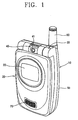
- Fig. 1 is a perspective view illustrating a portable terminal having a camera according to an example arrangement. Other arrangements are also possible.
- a portable terminal having the camera may include a main body 10 for inputting information and controlling communication, a folder 20 having a display (not shown) for outputting the information as an image, a hinge coupling device 30 for rotatably coupling the folder 20 to the main body 10, a camera unit 40 rotatably coupled to the hinge coupling device 30, and a battery 50 detachably coupled to the rear surface of the main body 10.
- Fig. 1 also shows an antenna 60, a speaker 70, an auxiliary display 22, and a lens 41 of a camera module.
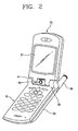
- the user may open the folder 20 from the main body 10 as shown in Fig. 2 .
- the folder 20 may be angularly rotated about an axis by using the hinge coupling device 30 as an axis.
- the folder 20 may have a predetermined angle relative to the main body 10.
- the user may telephone another user or answer the phone in a state in which the user opens the folder 20 from the main body 10.
- the user may open the folder 20 from the main body 10 as shown in Fig. 2 .
- the user may position the display 21 of the folder 20 and the lens 41 of the camera unit 40 in a same direction by rotating the camera unit 40.
- the user may adjust his/her image focused by the lens 41 and displayed on the display 21 by controlling the camera unit 40, and photograph himself/herself.
- the user may position the lens 41 of the camera unit 40 and the display 21 of the folder 20 in opposite directions by rotating the camera unit 40.
- the user may watch an image of the subject focused by the lens 41 and displayed on the display 21 by controlling the camera unit 40 and photograph the subject. After photographing the subject, the user may close the folder 20 to return to the original position.
- the user when the user photographs the still image or dynamic image of the subject using the camera unit 40, the user must open the folder 20 to photograph the subject.
- the user may adjust the image of the subject displayed on the display 21 by rotating the camera unit 40. That is, the portable terminal having the above-described camera may be disadvantageous in that the photographing process is complicated.
- the folder 20 and the main body 10 may have a predetermined angle, and thus the display 21 for displaying the image of the subject may be inclined at a predetermined angle. Accordingly, the user cannot easily adjust the image of the subject to a desired composition. While the user is photographing the subject, if the main body 10 or the folder 20 gets an impact, it may be easily broken because the folder 20 is angularly opened from the main body 10.
- Document JP 2002-111835 concerns a portable terminal comprising a main body and a slider unit, which are mounted for relative sliding movement in a longitudinal direction of the terminal.
- a camera unit including a camera is rotatably mounted to the slider unit in a top portion thereof. The axis of rotation of the camera unit relative to the slider unit is parallel to the widthwise direction of the terminal.
- Embodiments of the present invention may solve at least the above problems and/or disadvantages and provide at least the advantages described hereinafter.
- Embodiments of the present invention may provide a portable terminal having a digital camera function that allows the user to perform voice communication and/or easily photograph a still image or dynamic image of a subject.
- Embodiments of the present invention may provide a portable terminal having a digital camera function that allows the user to photograph a subject and that improves the structural intensity in a photographing state to prevent damages based on an external impact.
- Embodiments of the present invention may provide a portable terminal having a digital camera function.
- This may include a display main body, a camera assembly, a turning unit, a terminal main body, and a speaker/mike unit (hereafter also called a speaker and a mike unit).
- the display main body may have a display.
- the camera assembly may have a camera module for focusing on a subject and photographing an image of the subject displayed on the display.
- the turning unit may rotatably couple the display main body to the camera assembly.
- the terminal main body may have an information processing function and may be movably mounted on the display main body.
- the speaker unit and the mike unit may transmit and/or receive voice information.
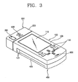
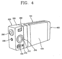
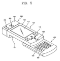
- FIGS. 3 to 5 are perspective views illustrating a portable terminal having a digital camera function according to an example embodiment of the present invention.
- the portable terminal having the digital camera function may include a display main body 100, a camera assembly 200, a turning unit 300, a terminal main body 400, a speaker unit 500 and a mike unit 600.
- the display main body 100 may have a display 110.
- the camera assembly 200 may have a camera module 210 for focusing on a subject and photographing an image of the subject displayed on the display 110.
- the turning unit 300 may rotatably couple the display main body 100 to the camera assembly 200.
- the terminal main body 400 may have an information processing function and be movably mounted on the display main body 100.
- the speaker unit 500 and the mike unit 600 may transmit and/or receive voice information.
- a sliding unit may move the terminal main body 400 in a lengthwise direction of the display main body 100.
- the sliding unit may be disposed in the terminal main body 400 and the display main body 100.
- the display main body 100 may include a main body casing 120 having a mounting unit 121 on which the terminal main body 400 is slidably positioned at its one side, and having circuit components inside.
- the display 110 may be coupled to the main body casing 120.
- Control buttons 130 may be formed at one side of the main body casing 120 for controlling the camera module 210.
- the main body casing 120 may be formed in a hexahedral shape having a predetermined width and length.
- the mounting unit 121 may be formed on one surface of the hexahedral shape.
- the mounting unit 121 is formed on one surface of the main body casing 120 to have a predetermined depth.
- the depth of the mounting unit 121 may correspond to the height (or depth) of the terminal main body 400, and the flat plate shape of the mounting unit 121 may correspond to the flat plate shape of the terminal main body 400.
- the display 110 may be coupled to the main body casing 120 on an opposite side as the mounting unit 121.
- the display 110 may include a liquid crystal screen for displaying various image information for calls as well as an image (or images) of a subject for photographing.
- the plurality of control buttons 130 may be formed on one surface of the main body casing 120.
- the control buttons 130 may be disposed next to the display 110.
- the control buttons 130 may have control functions for the camera module 210 such as zoom, photographing definition and shutter speed.
- the control buttons 130 may have a call start/end function, a power on/off function and a menu function as well as control functions for the camera module 210 in photographing.
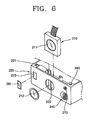
- the camera assembly 200 may include a camera casing 220 formed in a predetermined shape.
- the camera module 210 may mounted on the camera casing 220 and have a photographing button 230 mounted on the camera casing 220 and a flash 240 for lighting.
- the camera casing 220 may be formed in a hexahedral shape.
- the width and height of the hexahedron may be identical (or substantially identical) to those of the display main body 100.
- One surface of the camera assembly 200 and one surface of the display main body 100 may be coupled to contact each other by way of the turning unit 300.
- One surface of the camera assembly 200 and one surface of the display main body 100 contacting each other may be formed in the same shape.
- the camera module 210 may be mounted on one surface of the camera casing 220.
- the surface on which the camera module 210 is mounted may be vertical to the surface contacting the display main body 100.
- a coupling groove 221 may be formed in the camera casing 220 in a predetermined shape and the camera module 210 may be inserted into the coupling groove 221.
- the shape of the coupling groove 221 may correspond to the shape of the camera module 210.
- a through hole 222 may be provided on which a lens 211 composing the camera module 210 is formed on the surface of the camera casing 220 positioned on a side of the coupling groove 221.
- a protecting lens 212 for protecting the lens 211 of the camera module 210 may be coupled to the through hole 222.
- a mode select switch 250 may be formed on the camera assembly 200 for changing a photographing mode based on the photographing conditions.
- the mode select switch 250 may be mounted on one surface of the camera casing 220.
- the surface on which the mode select switch 250 is mounted may be an opposite surface as compared to the surface contacting the display main body 100.
- the mode select switch 250 may be a rotary type switch.
- the user may change the photographing mode into general photographing, clear day photographing, cloudy day photographing, night photographing, outdoor photographing, indoor photographing or close-up photographing, for example, by rotating (or otherwise operating) the mode select switch 250.
- An optimum shutter speed and an optimum exposure speed may be previously set for each of the photographing modes under specific conditions such as weather and brightness. Accordingly, the user may perform high quality photographing.
- the photographing button 230 may be positioned on the side of the mode select switch 250.
- a direct perspective device 260 may be formed on the camera assembly 200 to allow the user to see a subject with a naked eye when he/she is not able to see the subject through the display 110 due to high illumination, for example.
- the direct perspective device 260 may include a passage 223 passing through the camera casing 220, and transparent lenses 261 mounted on the passage 223.
- the transparent lenses 261 may be fixedly coupled to both surfaces of the camera casing 220 composing the passage 223.
- the flash 240 may be mounted on the camera casing 220 on the side of the camera module 210.
- the camera assembly 200 may include an auxiliary mike unit 270 for inputting photographing-related voice when photographing.
- the auxiliary mike unit 270 may be positioned at the side of the flash 240.
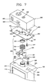
- the turning unit 300 may include a cylindrical shaft 310, a fixing protrusion 320, a cam holder 330, a cam unit 332, a spring insertion unit 333, a spring 340 and a fixing member 350.
- the cylindrical shaft 310 may be formed in a cylindrical shape on the display main body 100.
- the fixing protrusion 320 may be formed at the side of the cylindrical shaft 310.
- the cam holder 330 may be rotatably inserted onto the cylindrical shaft 310 and fixedly coupled to the camera assembly 200.
- the cam unit 332 may be formed at one side end of a cylindrical unit 331 having a larger inside diameter than an outside diameter of the cylindrical shaft 310 and a predetermined length.
- the spring insertion unit 333 may be formed at the other side of the cylindrical unit 331.
- the spring 340 may be inserted into the spring insertion unit 333 of the cam holder 330.
- the fixing member 350 may be fixedly coupled to the cylindrical shaft 310 inserted into the cylindrical unit 331 of the cam holder 330 for fixedly supporting the spring 340.
- the cylindrical shaft 310 may be formed on one surface of the main body casing 120 of the display main body 100 contacting the camera assembly 200.
- the cylindrical shaft 310 may be vertical to the surface.
- a through hole (not shown) corresponding to an inside diameter of the cylindrical shaft 310 may be formed on the surface of the main body casing 120 on which the cylindrical shaft 310 has been formed. Lines connecting the components of the camera assembly 200 to the components of the display main body 100 may be coupled through the through hole.
- the fixing protrusion 320 may be formed on one surface of the main body casing 120 at the side of the cylindrical shaft 310.
- the cam unit 332 of the cam holder 330 may be formed at the end of the cylindrical unit 331 in a waveform shape having a plurality of concave and convex parts.
- An angle of rotating the cam holder 330 may be dependent upon a number of the waveform shapes. When the number of the waveforms increases, the angle of rotating the cam holder 330 may decrease.
- the fixing member 350 may be a nut.
- a thread to which the nut may be coupled may be formed on the outer circumferential surface of the cylindrical shaft 310.
- the outside diameter of the fixing member 250 may be equal to or larger than the outside diameter of the spring 340.
- Coupling units 334 having a predetermined thickness and length may be formed at both sides of the outer circumferential surface of the cylindrical unit 331 of the cam holder 330, respectively, and through holes 335 may be formed on the coupling units 334.
- Screw holes 224 corresponding to the through holes 335 of the coupling units 334 may be formed on one surface of the camera assembly 200 contacting one surface of the display main body 100 (i.e., namely one surface of the camera casing 220 of the camera assembly 200).
- An insertion hole 225 into which the spring insertion unit 333 and the cylindrical unit 331 of the cam holder 330 are inserted may be formed between the screw holes 224.
- Fig. 7 further shows screws 281 and screw holes 282, 283.
- the cylindrical shaft 310 may be inserted into the cylindrical unit 331 of the cam holder 330.
- the spring 340 may be inserted into the spring insertion unit 333 of the cam holder 330 and the fixing member 350 may be fixedly coupled to the end of the cylindrical shaft 310 compressing the spring 340.
- the cam unit 332 of the cam holder 330 may adhere to one surface of the display main body 100 by elasticity of the spring 340 and may be engaged with the fixing protrusion 320.
- the coupling units 334 of the cam holder 330 may be fixedly coupled to one surface of the camera casing 220 by a plurality of bolts 336.
- the camera assembly 200 may be rotatably coupled to the display main body 100 by the turning unit 300.
- the cam unit 332 of the cam holder 330 and the fixing protrusion 320 that form the turning unit 300 may adhere to each other by the spring 340, and the cam holder 330 may be rotated.
- a sensing device may be provided for sensing rotation of the camera assembly 200.
- the sensing device may be formed on the camera assembly 200 and the display main body 100.
- the sensing device may include a magnet 391 mounted on the camera assembly 200, a sensor 392 mounted on one surface of the display main body 100 facing the magnet 391 for sensing a magnetic field of the magnet 391, and a signal line 393 for transmitting a signal sensed by the sensor 392.
- a plurality of magnets 391 may be circularly arranged at predetermined intervals by using a rotation axis for a relative motion of the camera assembly 200 and the display main body 100 as a concentric axis.
- the sensor 392 of the sensing device may sense the magnetic field of the magnet 391 to detect a rotation number or angle of the camera assembly 200.
- Various signal input methods may be used according to rotation of the camera assembly 200, or operation signals for turning on/off power.
- the speaker unit 500 may be installed on the camera assembly 200. More specifically, the speaker unit 500 may be installed on one surface of the camera casing 220 on the opposite side to the camera module 210.
- the mike unit 600 may be installed on the display main body 100. More specifically, the mike unit 600 may be installed on the main body casing 120 at sides of the control buttons 130. When the user talks over the phone, the speaker unit 500 installed on the camera assembly 200 and the mike unit 600 installed on the display main body 100 are positioned on the same surface.
- the terminal main body 400 may be formed in a hexahedral shape having a predetermined thickness.
- a keypad 410 for inputting information may be disposed on one surface of the terminal main body 400 and a battery 420 may be detachably mounted on the opposite surface thereof.
- the sliding unit may include guide grooves 122 formed with a predetermined width and length on the mounting surface of the display main body 100 on which the terminal main body 400 is mounted.
- a rack 123 may be formed on the mounting surface in parallel to the guide grooves 122.
- Guide protrusions 430 may protrude from one surface of the terminal main body 400 facing the mounting surface of the display main body 100, and may be slidably inserted into the guide grooves 122.
- a pinion 440 may be mounted on the terminal main body 400 and engaged with the rack 123.
- a driving motor 450 may rotate the pinion 440.
- the two guide grooves 122 may be formed in a length direction of the display main body 100 at predetermined intervals.
- the guide protrusions 430 may be press-fit into the guide grooves 122 and formed in a hook shape having a slit groove 431 to be separated from the guide grooves 122.
- the number of the guide protrusions 430 may correspond to the number of the guide grooves 122. That is, when two guide grooves 122 are formed, two guide protrusions 430 may be formed.
- the rack 123 may be formed in a length direction of the terminal main body 400 and may be positioned between the two guide grooves 122.
- a through hole 124 having a predetermined area may be formed on the mounting surface (i.e., one surface of the mounting unit 121 of the display main body 100).
- a through hole 460 corresponding to the through hole 124 may be formed on one surface of the terminal main body 400 facing the mounting surface of the display main body 100.
- the signal lines connecting the components of the display main body 100 to the components of the terminal main body 400 may be coupled through the through hole 124 of the display main body 100 and the through hole 460 of the terminal main body 400.
- the pinion 440 may be positioned inside the through hole 460 of the display main body 100, and may be externally protruded to be engaged with the rack 123 when the terminal main body 400 and the display main body 100 are coupled.
- the driving motor 450 may be mounted inside the terminal main body 400.
- the pinion 440 coupled to the driving motor 450 may be rotated in a forward or backward direction.
- the rack 123 engaged with the pinion 440 may perform a linear motion in one direction or in an opposite direction.
- the terminal main body 400 and the display main body 100 perform a relative motion so that the terminal main body 400 can slide to/from the mounting unit 121 of the display main body 100.
- the terminal main body 400 may perform a linear motion within a limited distance based on the guide grooves 122 and the guide protrusions 430.
- the terminal main body 400 may be hinge-coupled to one side of the display main body 100 by a hinge device.
- An open/close switch 470 may be provided for operating the driving motor 450. Operational effects of the portable terminal having a digital camera function in accordance with an example embodiment of the present invention will now be described.
- the user may answer the phone by pressing one of the control buttons 130 and phone another user by pulling the terminal main body 400 from the display main body 100 by the sliding unit and using the keypad 410 and the control buttons 130 of the terminal main body 400.
- the speaker unit 500, the display 110 and the mike unit 600 are positioned on the same surface.
- the display 110 may display image information.
- the terminal main body 400 may slide to/from the mounting unit 121 of the display main body 100 by the sliding unit.
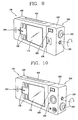
- the user may position the camera module 210 and the display 110 in the opposite directions by rotating the camera assembly 200.
- the camera module 210 may be rotated by the turning unit 300.
- the user may see an image of the subject focused by the camera module 210 and displayed on the display 110, and photograph the wanted image of the subject.
- the camera module 210 and the display 110 may be positioned at different angles such as at an angle of 180° with respect to each other.
- the user may not clearly distinguish the image of the subject displayed on the display 110. Accordingly, the user may photograph the subject seeing the subject with the naked eye through the direct perspective device 260.
- the user may position the camera module 210 and the display 110 in the same direction by rotating the camera assembly 200.
- the user may see his/her image focused by the camera module 210 and displayed on the display 110, and photograph the wanted image.
- the user may photograph a still image or dynamic images of the subject or the user himself/herself when the terminal main body 400 slides to/from the mounting unit 121 of the display main body 100.
- the portable terminal having the digital camera function may allow the user to perform voice communication and photograph the subject or the user himself/herself by rotating the camera assembly 200 or the display main body 100. Therefore, the photographing process may be simplified. Conversely, the portable terminal may not be convenient since the user may have to open the folder 20 to photograph the subject or the user himself/herself.
- the user when the user is not able to clearly see the subject through the display 110 in a lighted place, the user may easily photograph the subject seeing the subject with the naked eye.
- the display main body 100 and the camera assembly 200 may be arranged in a straight line to improve the structural intensity.
- the portable terminal having the digital camera function may allow the user to perform voice communication and to easily photograph still images or dynamic images resulting in the user's satisfaction.
- the portable terminal having the digital camera function shows high structural intensity in the photographing state to prevent damages by an external impact and improve reliability.
- the portable terminal allows the user to freely photograph still images or dynamic images with high satisfaction.
Landscapes
- Engineering & Computer Science (AREA)
- Signal Processing (AREA)
- Multimedia (AREA)
- Computer Networks & Wireless Communication (AREA)
- Studio Devices (AREA)
- Telephone Set Structure (AREA)
- Telephone Function (AREA)
- Details Of Cameras Including Film Mechanisms (AREA)
- Camera Bodies And Camera Details Or Accessories (AREA)
Claims (23)
- Terminal portable ayant une fonction d'appareil photographique numérique comprenant- un corps principal d'afficheur (100) ayant un afficheur (110), et- un ensemble d'appareil photographique (200) couplé au corps principal d'afficheur (100) pour un mouvement rotatif relatif et ayant un module d'appareil photographique (210) pour focaliser sur un sujet et pour photographier une image du sujet, par quoi l'ensemble d'appareil photographique (200) est agencé pour une rotation autour d'un axe de rotation perpendiculaire à une direction de la largeur du corps principal d'afficheur (100),caractérisé en ce que le terminal portable comprend en outre un corps principal de terminal (400) monté de façon mobile sur le corps principal d'afficheur et une unité tournante (300) pour coupler à rotation l'ensemble d'appareil photographique (200) au corps principal d'afficheur (100), l'unité tournante (300) incluant un arbre cylindrique (310) formé à une forme cylindrique, et un porte-came (330) dans lequel l'arbre cylindrique (310) est inséré à rotation,
dans lequel une saillie de fixation (320) est formée sur un côté de l'arbre cylindrique (310), et une unité de came (332) est formée à une extrémité d'une unité cylindrique (331) du porte-came (330) et ayant une pluralité de parties concaves et convexes et un ressort (340) pour presser l'unité de came (332) sur la saillie de fixation (320),
dans lequel l'ensemble d'appareil photographique (200) est adapté pour stopper instantanément lorsque la saillie de fixation (320) est engagée avec l'une des parties concaves. - Terminal portable selon la revendication 1, dans lequel le corps principal d'afficheur (100) inclut un boîtier de corps principal (120) ayant une unité de montage (121) sur laquelle le corps principal de terminal (400) est positionné à coulissement, le boîtier de corps principal (120) ayant des composants de circuits, l'afficheur (110) couplé au boîtier de corps principal (120), et des boutons de commande (130) prévus sur un côté du boîtier de corps principal (120) pour commander le module d'appareil photographique (210).
- Terminal portable selon la revendication 2, dans lequel le boîtier de corps principal (120) est formé à une forme substantiellement hexaédrique ayant une largeur et une longueur prédéterminées, et l'unité de montage (121) est formée sur une surface de la forme d'hexaèdre avec une surface différentielle à épaulement ayant une hauteur prédéterminée.
- Terminal portable selon la revendication 3, dans lequel la hauteur de la surface différentielle à épaulement de l'unité de montage (121) correspond à une épaisseur du corps principal de terminal (400).
- Terminal portable selon la revendication 1, dans lequel l'afficheur (110) inclut un écran à cristaux liquides pour afficher les informations d'image et pour afficher l'image du sujet.
- Terminal portable selon la revendication 1, dans lequel l'ensemble d'appareil photographique (200) inclut un boîtier d'appareil photographique (220) formé à une forme prédéterminée et ayant, monté dans celui-ci, le module d'appareil photographique (210), l'ensemble d'appareil photographique incluant en outre un bouton de prise de vues (230) sur le boîtier d'appareil photographique et un flash (240) pour l'éclairage.
- Terminal portable selon la revendication 6, dans lequel le boîtier d'appareil photographique (220) est formé à une forme hexaédrique, et une largeur et une hauteur de la forme d'hexaèdre correspondent à une largeur et une hauteur du corps principal d'afficheur (100).
- Terminal portable selon la revendication 6, dans lequel l'ensemble d'appareil photographique (200) inclut un commutateur de sélection de mode (250) pour changer un mode de prise de vues.
- Terminal portable selon la revendication 6, dans lequel l'ensemble d'appareil photographique (200) inclut un dispositif de perspective directe (260) pour permettre à l'utilisateur de voir le sujet à travers le dispositif de perspective directe.
- Terminal portable selon la revendication 9, dans lequel le dispositif de perspective directe (260) inclut un passage (223) passant à travers le boîtier d'appareil photographique (220), et des lentilles transparentes (261) montées dans le passage.
- Terminal portable selon la revendication 6, dans lequel l'ensemble d'appareil photographique (200) inclut une unité de microphone auxiliaire (270) pour entrer des informations vocales.
- Terminal portable selon la revendication 6, dans lequel une rainure de couplage (221) est formée dans le boîtier d'appareil photographique (220) à une forme prédéterminée, et le module d'appareil photographique (210) est inséré dans la rainure de couplage (221).
- Terminal portable selon la revendication 1, dans lequel l'arbre cylindrique (310) est formé sur le corps principal d'afficheur (100), et le porte-came (330) est couplé de façon fixe à l'ensemble d'appareil photographique (200).
- Terminal portable selon la revendication 13, dans lequel le terminal mobile comprend en outre un élément de fixation (350) couplé à une extrémité de l'arbre cylindrique (310) de sorte que le porte-came (330) puisse être couplé à coulissement à l'arbre cylindrique (310) dans une direction de sa longueur, et le ressort (340) est installé entre le porte-came (330) et l'élément de fixation (350).
- Terminal portable selon la revendication 14, dans lequel le porte-came comprend en outre une unité d'insertion de ressort (333) formée à une autre extrémité de l'unité cylindrique (331) pour recevoir le ressort (340).
- Terminal portable selon la revendication 1, dans lequel un dispositif de détection pour détecter la rotation de l'ensemble d'appareil photographique (200) est prévu sur l'ensemble d'appareil photographique et le corps principal d'afficheur (100).
- Terminal portable selon la revendication 16, dans lequel le dispositif de détection inclut un aimant (391) monté sur l'ensemble d'appareil photographique (200), un détecteur (392) monté sur une surface du corps principal d'afficheur (100) face à l'aimant, et une ligne de signaux, le détecteur pour détecter un champ magnétique de l'aimant, et la ligne de signaux pour transmettre un signal détecté par le détecteur.
- Terminal portable selon la revendication 17, dans lequel une pluralité d'aimants (391) sont agencés à des intervalles prédéterminés en utilisant l'axe de rotation autour duquel l'ensemble d'appareil photographique (200) et le corps principal d'afficheur (100) tournent l'un par rapport à l'autre, comme un axe concentrique.
- Terminal portable selon la revendication 1, comprenant en outre une unité de haut-parleur (500) positionnée sur l'ensemble d'appareil photographique (200).
- Terminal portable selon la revendication 1, comprenant en outre une unité de microphone (600) positionnée sur le corps principal d'afficheur (100).
- Terminal portable selon la revendication 1, comprenant en outre des rainures de guidage (122) formées avec une largeur et une longueur prédéterminées sur une surface de montage du corps principal d'afficheur (100) sur laquelle le corps principal de terminal (400) est monté, une crémaillère (123) formée sur la surface de montage en parallèle avec les rainures de guidage (122), des saillies de guidage (430) faisant saillie d'une surface du corps principal de terminal (400) qui fait face à la surface de montage du corps principal d'afficheur (100), dans lequel les saillies de guidage sont insérées dans les rainures de guidage pour un mouvement de coulissement dans celles-ci, un pignon (440) monté sur le corps principal de terminal (400) et s'engageant dans la crémaillère (123), et un moteur d'entraînement (450) pour faire tourner le pignon (440).
- Terminal portable selon la revendication 21, dans lequel deux rainures de guidage (122) sont formées selon une séparation mutuelle prédéterminée, et deux saillies de guidage (430) sont insérées dans les deux rainures de guidage.
- Terminal portable selon la revendication 21, dans lequel un trou traversant (124) ayant une aire prédéterminée est formé sur la surface de montage formant l'unité de montage (121) du corps principal d'afficheur (100), et un trou traversant correspondant (460) est formé sur une surface du corps principal de terminal (400) faisant face à la surface de montage du corps principal d'afficheur.
Priority Applications (1)
| Application Number | Priority Date | Filing Date | Title |
|---|---|---|---|
| EP08006879A EP1944950B1 (fr) | 2003-12-26 | 2004-12-23 | Terminal portable doté d'une fonction caméra numérique |
Applications Claiming Priority (2)
| Application Number | Priority Date | Filing Date | Title |
|---|---|---|---|
| KR1020030097904A KR100608732B1 (ko) | 2003-12-26 | 2003-12-26 | 디지털 카메라 기능을 갖는 휴대용 단말기 |
| KR2003097904 | 2003-12-26 |
Related Child Applications (1)
| Application Number | Title | Priority Date | Filing Date |
|---|---|---|---|
| EP08006879A Division EP1944950B1 (fr) | 2003-12-26 | 2004-12-23 | Terminal portable doté d'une fonction caméra numérique |
Publications (2)
| Publication Number | Publication Date |
|---|---|
| EP1549029A1 EP1549029A1 (fr) | 2005-06-29 |
| EP1549029B1 true EP1549029B1 (fr) | 2008-04-09 |
Family
ID=34545918
Family Applications (2)
| Application Number | Title | Priority Date | Filing Date |
|---|---|---|---|
| EP08006879A Expired - Lifetime EP1944950B1 (fr) | 2003-12-26 | 2004-12-23 | Terminal portable doté d'une fonction caméra numérique |
| EP04030681A Expired - Lifetime EP1549029B1 (fr) | 2003-12-26 | 2004-12-23 | Terminal portable avec fonction d'appareil photographique numérique. |
Family Applications Before (1)
| Application Number | Title | Priority Date | Filing Date |
|---|---|---|---|
| EP08006879A Expired - Lifetime EP1944950B1 (fr) | 2003-12-26 | 2004-12-23 | Terminal portable doté d'une fonction caméra numérique |
Country Status (7)
| Country | Link |
|---|---|
| US (3) | US7636124B2 (fr) |
| EP (2) | EP1944950B1 (fr) |
| JP (1) | JP4625323B2 (fr) |
| KR (1) | KR100608732B1 (fr) |
| CN (1) | CN1638403B (fr) |
| AT (2) | ATE445963T1 (fr) |
| DE (2) | DE602004023660D1 (fr) |
Families Citing this family (31)
| Publication number | Priority date | Publication date | Assignee | Title |
|---|---|---|---|---|
| KR100617681B1 (ko) * | 2003-04-15 | 2006-08-28 | 삼성전자주식회사 | 휴대용 단말기의 회전키 장치 사용 방법 |
| FI20050106A7 (fi) * | 2005-01-31 | 2006-08-01 | Elcoteq Se | Matkaviestinlaite |
| US7747004B2 (en) * | 2005-12-22 | 2010-06-29 | Motorola, Inc. | Devices and methods for acoustic usability |
| USD566082S1 (en) * | 2005-12-22 | 2008-04-08 | Samsung Electronics Co., Ltd. | Mobile phone |
| KR100713433B1 (ko) | 2006-01-27 | 2007-05-04 | 삼성전자주식회사 | 자기 거치 타입 휴대 단말기 |
| CN101433062B (zh) * | 2006-03-02 | 2011-11-09 | 松下电器产业株式会社 | 便携终端 |
| US7672584B2 (en) * | 2006-03-06 | 2010-03-02 | Samsung Electronics Co., Ltd. | Digital device |
| KR100837433B1 (ko) * | 2006-03-06 | 2008-06-12 | 삼성전자주식회사 | 디지털 기기 |
| KR100842527B1 (ko) * | 2006-04-17 | 2008-07-01 | 삼성전자주식회사 | 휴대용 단말기의 힌지 장치 |
| JP4767833B2 (ja) * | 2006-12-15 | 2011-09-07 | 富士通株式会社 | 電子機器およびカメラモジュールユニット |
| USD562295S1 (en) * | 2007-02-26 | 2008-02-19 | Howard Lindner | Solar cell phone |
| WO2008120706A1 (fr) * | 2007-03-30 | 2008-10-09 | Nec Corporation | Structure coulissante pour dispositif portable, et dispositif portable |
| DE102007031559A1 (de) * | 2007-07-06 | 2009-01-08 | Robert Bosch Gmbh | Tragbares elektronisches Gerät |
| TWI330062B (en) * | 2007-12-07 | 2010-09-01 | Htc Corp | Handheld electronic device |
| TWI386008B (zh) * | 2008-01-22 | 2013-02-11 | Asustek Comp Inc | 可攜式電子裝置 |
| CN101742859A (zh) * | 2008-11-20 | 2010-06-16 | 深圳富泰宏精密工业有限公司 | 便携式电子装置 |
| CN101750698A (zh) * | 2008-12-10 | 2010-06-23 | 深圳富泰宏精密工业有限公司 | 镜头模组及应用该镜头模组的电子装置 |
| CN101753647A (zh) * | 2008-12-22 | 2010-06-23 | 鸿富锦精密工业(深圳)有限公司 | 分体式手机 |
| CN101990011B (zh) * | 2009-07-29 | 2013-11-20 | 鸿富锦精密工业(深圳)有限公司 | 可携式电子装置 |
| TWI387429B (zh) * | 2009-08-25 | 2013-02-21 | Wistron Corp | 具有可拆卸式攝影模組之可攜式電子系統 |
| KR101594367B1 (ko) * | 2009-09-02 | 2016-02-26 | 엘지전자 주식회사 | 휴대용 단말기 |
| KR101094767B1 (ko) * | 2010-05-19 | 2011-12-16 | 엘지전자 주식회사 | 휴대용 전자기기 |
| CN102928833B (zh) * | 2011-08-10 | 2014-03-19 | 广州三星通信技术研究有限公司 | 用于便携式终端的防撞装置、防撞方法以及便携式终端 |
| JP5456082B2 (ja) * | 2012-02-03 | 2014-03-26 | キヤノン株式会社 | 電子機器 |
| CN104238579B (zh) * | 2014-09-26 | 2017-05-24 | 广东欧珀移动通信有限公司 | 一种应用于移动终端的摄像头旋转控制方法和移动终端 |
| EP3210437B1 (fr) * | 2014-10-16 | 2020-05-27 | LG Electronics Inc. | Terminal de type montre et son procédé de commande |
| WO2016195144A1 (fr) * | 2015-06-05 | 2016-12-08 | 엘지전자 주식회사 | Module appareil photo, et terminal mobile le comprenant |
| CN104980544B (zh) * | 2015-07-13 | 2016-10-26 | 广东欧珀移动通信有限公司 | 一种两端可折弯的柔性屏移动终端 |
| CN204859341U (zh) * | 2015-08-11 | 2015-12-09 | 深圳遨乐科技有限公司 | 一种fancam带转轴迷你运动相机 |
| CN110022428B (zh) * | 2019-05-24 | 2020-11-06 | 维沃移动通信(杭州)有限公司 | 摄像头模组、终端设备及信息处理方法 |
| US11812127B2 (en) * | 2021-10-27 | 2023-11-07 | Dell Products L.P. | Monitor with integrated camera to achieve optimized vertical dimension |
Family Cites Families (33)
| Publication number | Priority date | Publication date | Assignee | Title |
|---|---|---|---|---|
| US4543609A (en) * | 1981-01-19 | 1985-09-24 | Lectrolarm Custom Systems, Inc. | Television surveillance system |
| JP2778876B2 (ja) | 1992-07-09 | 1998-07-23 | 極東鋼弦コンクリート振興株式会社 | 斜張橋のケーブル装着用案内装置 |
| JPH08294030A (ja) | 1995-04-19 | 1996-11-05 | Hitachi Ltd | 携帯電話一体型ビデオカメラ |
| WO1997008888A1 (fr) | 1995-08-25 | 1997-03-06 | Hitachi, Ltd. | Enregistreur equipe d'une camera video |
| JP3153747B2 (ja) | 1995-10-26 | 2001-04-09 | シャープ株式会社 | 無線式画像伝送電話機 |
| JPH1070485A (ja) | 1996-08-27 | 1998-03-10 | Saitama Nippon Denki Kk | 携帯電話機の構造 |
| JPH1075287A (ja) | 1996-08-30 | 1998-03-17 | Kokusai Electric Co Ltd | 携帯テレビ電話 |
| US6295088B1 (en) * | 1997-02-17 | 2001-09-25 | Nikon Corporation | Portable display device |
| JP3988102B2 (ja) | 1998-11-06 | 2007-10-10 | 富士フイルム株式会社 | 腕装着型カメラ |
| JP2000165718A (ja) | 1998-11-30 | 2000-06-16 | Matsushita Electric Ind Co Ltd | 電子撮像装置 |
| JP2001245267A (ja) * | 2000-02-28 | 2001-09-07 | Matsushita Electric Ind Co Ltd | ビデオカメラ付き携帯型情報通信端末装置 |
| JP2002057759A (ja) * | 2000-08-09 | 2002-02-22 | Nec Saitama Ltd | 折り畳み可能な携帯電話 |
| JP3751197B2 (ja) | 2000-10-02 | 2006-03-01 | 株式会社ケンウッド | 移動体電話機 |
| JP2002141990A (ja) | 2000-10-31 | 2002-05-17 | Kyocera Corp | 携帯テレビ電話機 |
| KR100438433B1 (ko) * | 2001-06-26 | 2004-07-03 | 삼성전자주식회사 | 피디에이 겸용 디지털 카메라 통신 휴대 장치 |
| JP2003031968A (ja) | 2001-07-11 | 2003-01-31 | Kyocera Corp | 電子端末装置 |
| JP3810294B2 (ja) | 2001-09-07 | 2006-08-16 | シャープ株式会社 | 携帯電話機 |
| JP2003110680A (ja) | 2001-09-27 | 2003-04-11 | Sanyo Electric Co Ltd | 携帯式通信機 |
| WO2003030518A1 (fr) | 2001-09-28 | 2003-04-10 | Telefonaktiebolaget L. M. Ericsson (Publ) | Terminal mobile de communications |
| JP2003120652A (ja) | 2001-10-12 | 2003-04-23 | Strawberry Corporation | ヒンジ装置並びにヒンジ装置を用いた電子機器 |
| CN1284059C (zh) | 2001-11-27 | 2006-11-08 | 皇家飞利浦电子股份有限公司 | 便携式电子装置 |
| KR100450581B1 (ko) * | 2002-02-28 | 2004-09-30 | 삼성전자주식회사 | 힌지 장치 및 그를 채용한 휴대용 단말기 |
| JP4055116B2 (ja) * | 2002-05-07 | 2008-03-05 | 日本電気株式会社 | 携帯電話機 |
| JP2004056408A (ja) | 2002-07-19 | 2004-02-19 | Hitachi Ltd | 携帯電話端末 |
| US6967247B2 (en) * | 2002-07-24 | 2005-11-22 | Isis Pharmaceuticals, Inc. | Deprotection of phosphorus in oligonucleotide synthesis |
| KR100484732B1 (ko) * | 2002-11-19 | 2005-04-22 | 삼성전자주식회사 | 슬라이딩 타입 휴대용 무선 단말기 |
| JP4101043B2 (ja) * | 2002-12-11 | 2008-06-11 | キヤノン株式会社 | 画像データ表示システム及びその画像データ表示方法、並びにプログラム、記憶媒体及び撮像装置 |
| KR100575999B1 (ko) * | 2003-03-10 | 2006-05-02 | 삼성전자주식회사 | 바 타입 휴대용 무선 단말기 |
| US20040192220A1 (en) * | 2003-03-24 | 2004-09-30 | Inventec Appliances Corp. | Mechanism for switching cellular phone to digital camera |
| FI118668B (fi) * | 2003-04-01 | 2008-01-31 | Samsung Electro Mech | Matkapuhelin ja sen automaattinen pyöritysmenetelmä |
| FI118669B (fi) * | 2003-04-01 | 2008-01-31 | Samsung Electro Mech | Liukutyyppinen matkapuhelin ja liukumismenetelmä siihen |
| JP4187607B2 (ja) * | 2003-08-14 | 2008-11-26 | 富士通株式会社 | 移動式無線通信装置 |
| US7565183B2 (en) * | 2004-11-15 | 2009-07-21 | Sony Ericsson Mobile Communications Ab | Mobile device with selectable camera position |
-
2003
- 2003-12-26 KR KR1020030097904A patent/KR100608732B1/ko not_active Expired - Fee Related
-
2004
- 2004-12-21 US US11/016,759 patent/US7636124B2/en not_active Expired - Fee Related
- 2004-12-22 JP JP2004371021A patent/JP4625323B2/ja not_active Expired - Fee Related
- 2004-12-23 AT AT08006879T patent/ATE445963T1/de not_active IP Right Cessation
- 2004-12-23 DE DE602004023660T patent/DE602004023660D1/de not_active Expired - Lifetime
- 2004-12-23 AT AT04030681T patent/ATE392083T1/de not_active IP Right Cessation
- 2004-12-23 DE DE602004012954T patent/DE602004012954T2/de not_active Expired - Lifetime
- 2004-12-23 EP EP08006879A patent/EP1944950B1/fr not_active Expired - Lifetime
- 2004-12-23 EP EP04030681A patent/EP1549029B1/fr not_active Expired - Lifetime
- 2004-12-24 CN CN2004100615411A patent/CN1638403B/zh not_active Expired - Fee Related
-
2006
- 2006-12-18 US US11/640,333 patent/US7742100B2/en not_active Expired - Fee Related
- 2006-12-18 US US11/640,335 patent/US7692717B2/en not_active Expired - Fee Related
Also Published As
| Publication number | Publication date |
|---|---|
| US20070097248A1 (en) | 2007-05-03 |
| EP1944950A2 (fr) | 2008-07-16 |
| US20070099656A1 (en) | 2007-05-03 |
| US7742100B2 (en) | 2010-06-22 |
| CN1638403B (zh) | 2010-05-26 |
| US7636124B2 (en) | 2009-12-22 |
| DE602004012954D1 (de) | 2008-05-21 |
| EP1944950A3 (fr) | 2008-09-03 |
| US20050140811A1 (en) | 2005-06-30 |
| JP2005198279A (ja) | 2005-07-21 |
| CN1638403A (zh) | 2005-07-13 |
| ATE392083T1 (de) | 2008-04-15 |
| EP1549029A1 (fr) | 2005-06-29 |
| KR100608732B1 (ko) | 2006-08-04 |
| KR20050066596A (ko) | 2005-06-30 |
| DE602004012954T2 (de) | 2009-05-28 |
| ATE445963T1 (de) | 2009-10-15 |
| EP1944950B1 (fr) | 2009-10-14 |
| JP4625323B2 (ja) | 2011-02-02 |
| US7692717B2 (en) | 2010-04-06 |
| DE602004023660D1 (de) | 2009-11-26 |
Similar Documents
| Publication | Publication Date | Title |
|---|---|---|
| EP1549029B1 (fr) | Terminal portable avec fonction d'appareil photographique numérique. | |
| EP1469656A2 (fr) | Téléphone mobile avec un boítier rotatif pour un objectif de caméra | |
| EP2206014B1 (fr) | Dispositif électronique portable ayant une caméra haute résolution avec une mise au point automatique de détecteur accordable | |
| US20070070184A1 (en) | Mobile Communication Device With Enhanced Image Communication Capability | |
| KR100703402B1 (ko) | 다방향으로 촬영되는 카메라 렌즈 모듈을 구비한 휴대단말기 | |
| EP3525429B1 (fr) | Un terminal mobile à coques coulissantes comprenant une caméra | |
| KR100593177B1 (ko) | 광학 줌 기능이 가능한 휴대용 단말기 카메라 모듈 | |
| CN111294428A (zh) | 电子设备 | |
| KR20030089359A (ko) | 줌 기능을 갖는 촬상소자 모듈 | |
| CN112437214B (zh) | 电子设备及其摄像头单元 | |
| JP2004208176A (ja) | 携帯端末機器 | |
| US20050047770A1 (en) | Imaging device and portable equipment | |
| KR100557065B1 (ko) | 회전성 카메라 렌즈 하우징을 구비한 휴대용 단말기 | |
| JP3839749B2 (ja) | 携帯電話機 | |
| KR100526652B1 (ko) | 소형 휴대단말기용 카메라장치 | |
| KR100548424B1 (ko) | 슬라이드형 휴대용 단말기의 줌카메라 | |
| JP2005107073A (ja) | 撮影装置 | |
| JP2005107074A (ja) | 携帯型電子機器 | |
| KR20050020515A (ko) | 휴대용 단말기의 카메라 줌장치 | |
| TWI421623B (zh) | 相機模組及使用該相機模組的可攜式電子裝置 | |
| HK40012082B (en) | A mobile terminal with sliding shells comprising a camera | |
| KR20060032489A (ko) | 이동단말기의 길이측정장치 | |
| HK40012082A (en) | A mobile terminal with sliding shells comprising a camera | |
| KR20050041632A (ko) | 휴대용 디지털 통신 단말기 | |
| JP2001313863A (ja) | 撮像装置、撮像装置一体型ハンドセット電話機及び撮像装置一体型携帯情報機器 |
Legal Events
| Date | Code | Title | Description |
|---|---|---|---|
| PUAI | Public reference made under article 153(3) epc to a published international application that has entered the european phase |
Free format text: ORIGINAL CODE: 0009012 |
|
| 17P | Request for examination filed |
Effective date: 20041223 |
|
| AK | Designated contracting states |
Kind code of ref document: A1 Designated state(s): AT BE BG CH CY CZ DE DK EE ES FI FR GB GR HU IE IS IT LI LT LU MC NL PL PT RO SE SI SK TR |
|
| AX | Request for extension of the european patent |
Extension state: AL BA HR LV MK YU |
|
| AKX | Designation fees paid |
Designated state(s): AT BE BG CH CY CZ DE DK EE ES FI FR GB GR HU IE IS IT LI LT LU MC NL PL PT RO SE SI SK TR |
|
| 17Q | First examination report despatched |
Effective date: 20051114 |
|
| GRAP | Despatch of communication of intention to grant a patent |
Free format text: ORIGINAL CODE: EPIDOSNIGR1 |
|
| GRAS | Grant fee paid |
Free format text: ORIGINAL CODE: EPIDOSNIGR3 |
|
| GRAA | (expected) grant |
Free format text: ORIGINAL CODE: 0009210 |
|
| AK | Designated contracting states |
Kind code of ref document: B1 Designated state(s): AT BE BG CH CY CZ DE DK EE ES FI FR GB GR HU IE IS IT LI LT LU MC NL PL PT RO SE SI SK TR |
|
| REG | Reference to a national code |
Ref country code: GB Ref legal event code: FG4D |
|
| REG | Reference to a national code |
Ref country code: CH Ref legal event code: EP |
|
| REG | Reference to a national code |
Ref country code: IE Ref legal event code: FG4D |
|
| REF | Corresponds to: |
Ref document number: 602004012954 Country of ref document: DE Date of ref document: 20080521 Kind code of ref document: P |
|
| PG25 | Lapsed in a contracting state [announced via postgrant information from national office to epo] |
Ref country code: SI Free format text: LAPSE BECAUSE OF FAILURE TO SUBMIT A TRANSLATION OF THE DESCRIPTION OR TO PAY THE FEE WITHIN THE PRESCRIBED TIME-LIMIT Effective date: 20080409 |
|
| PG25 | Lapsed in a contracting state [announced via postgrant information from national office to epo] |
Ref country code: BG Free format text: LAPSE BECAUSE OF FAILURE TO SUBMIT A TRANSLATION OF THE DESCRIPTION OR TO PAY THE FEE WITHIN THE PRESCRIBED TIME-LIMIT Effective date: 20080709 Ref country code: ES Free format text: LAPSE BECAUSE OF FAILURE TO SUBMIT A TRANSLATION OF THE DESCRIPTION OR TO PAY THE FEE WITHIN THE PRESCRIBED TIME-LIMIT Effective date: 20080720 Ref country code: PT Free format text: LAPSE BECAUSE OF FAILURE TO SUBMIT A TRANSLATION OF THE DESCRIPTION OR TO PAY THE FEE WITHIN THE PRESCRIBED TIME-LIMIT Effective date: 20080909 |
|
| PG25 | Lapsed in a contracting state [announced via postgrant information from national office to epo] |
Ref country code: PL Free format text: LAPSE BECAUSE OF FAILURE TO SUBMIT A TRANSLATION OF THE DESCRIPTION OR TO PAY THE FEE WITHIN THE PRESCRIBED TIME-LIMIT Effective date: 20080409 Ref country code: AT Free format text: LAPSE BECAUSE OF FAILURE TO SUBMIT A TRANSLATION OF THE DESCRIPTION OR TO PAY THE FEE WITHIN THE PRESCRIBED TIME-LIMIT Effective date: 20080409 |
|
| PG25 | Lapsed in a contracting state [announced via postgrant information from national office to epo] |
Ref country code: IS Free format text: LAPSE BECAUSE OF FAILURE TO SUBMIT A TRANSLATION OF THE DESCRIPTION OR TO PAY THE FEE WITHIN THE PRESCRIBED TIME-LIMIT Effective date: 20080809 |
|
| ET | Fr: translation filed | ||
| PG25 | Lapsed in a contracting state [announced via postgrant information from national office to epo] |
Ref country code: LT Free format text: LAPSE BECAUSE OF FAILURE TO SUBMIT A TRANSLATION OF THE DESCRIPTION OR TO PAY THE FEE WITHIN THE PRESCRIBED TIME-LIMIT Effective date: 20080409 Ref country code: CZ Free format text: LAPSE BECAUSE OF FAILURE TO SUBMIT A TRANSLATION OF THE DESCRIPTION OR TO PAY THE FEE WITHIN THE PRESCRIBED TIME-LIMIT Effective date: 20080409 Ref country code: DK Free format text: LAPSE BECAUSE OF FAILURE TO SUBMIT A TRANSLATION OF THE DESCRIPTION OR TO PAY THE FEE WITHIN THE PRESCRIBED TIME-LIMIT Effective date: 20080409 |
|
| PLBE | No opposition filed within time limit |
Free format text: ORIGINAL CODE: 0009261 |
|
| STAA | Information on the status of an ep patent application or granted ep patent |
Free format text: STATUS: NO OPPOSITION FILED WITHIN TIME LIMIT |
|
| PG25 | Lapsed in a contracting state [announced via postgrant information from national office to epo] |
Ref country code: BE Free format text: LAPSE BECAUSE OF FAILURE TO SUBMIT A TRANSLATION OF THE DESCRIPTION OR TO PAY THE FEE WITHIN THE PRESCRIBED TIME-LIMIT Effective date: 20080409 Ref country code: SK Free format text: LAPSE BECAUSE OF FAILURE TO SUBMIT A TRANSLATION OF THE DESCRIPTION OR TO PAY THE FEE WITHIN THE PRESCRIBED TIME-LIMIT Effective date: 20080409 Ref country code: RO Free format text: LAPSE BECAUSE OF FAILURE TO SUBMIT A TRANSLATION OF THE DESCRIPTION OR TO PAY THE FEE WITHIN THE PRESCRIBED TIME-LIMIT Effective date: 20080409 |
|
| 26N | No opposition filed |
Effective date: 20090112 |
|
| PG25 | Lapsed in a contracting state [announced via postgrant information from national office to epo] |
Ref country code: EE Free format text: LAPSE BECAUSE OF FAILURE TO SUBMIT A TRANSLATION OF THE DESCRIPTION OR TO PAY THE FEE WITHIN THE PRESCRIBED TIME-LIMIT Effective date: 20080409 |
|
| PG25 | Lapsed in a contracting state [announced via postgrant information from national office to epo] |
Ref country code: MC Free format text: LAPSE BECAUSE OF NON-PAYMENT OF DUE FEES Effective date: 20081231 |
|
| REG | Reference to a national code |
Ref country code: CH Ref legal event code: PL |
|
| PG25 | Lapsed in a contracting state [announced via postgrant information from national office to epo] |
Ref country code: CY Free format text: LAPSE BECAUSE OF FAILURE TO SUBMIT A TRANSLATION OF THE DESCRIPTION OR TO PAY THE FEE WITHIN THE PRESCRIBED TIME-LIMIT Effective date: 20080409 |
|
| PG25 | Lapsed in a contracting state [announced via postgrant information from national office to epo] |
Ref country code: CH Free format text: LAPSE BECAUSE OF NON-PAYMENT OF DUE FEES Effective date: 20081231 Ref country code: IE Free format text: LAPSE BECAUSE OF NON-PAYMENT OF DUE FEES Effective date: 20081223 Ref country code: LI Free format text: LAPSE BECAUSE OF NON-PAYMENT OF DUE FEES Effective date: 20081231 |
|
| PG25 | Lapsed in a contracting state [announced via postgrant information from national office to epo] |
Ref country code: HU Free format text: LAPSE BECAUSE OF FAILURE TO SUBMIT A TRANSLATION OF THE DESCRIPTION OR TO PAY THE FEE WITHIN THE PRESCRIBED TIME-LIMIT Effective date: 20081010 Ref country code: LU Free format text: LAPSE BECAUSE OF NON-PAYMENT OF DUE FEES Effective date: 20081223 |
|
| PG25 | Lapsed in a contracting state [announced via postgrant information from national office to epo] |
Ref country code: TR Free format text: LAPSE BECAUSE OF FAILURE TO SUBMIT A TRANSLATION OF THE DESCRIPTION OR TO PAY THE FEE WITHIN THE PRESCRIBED TIME-LIMIT Effective date: 20080409 |
|
| PG25 | Lapsed in a contracting state [announced via postgrant information from national office to epo] |
Ref country code: GR Free format text: LAPSE BECAUSE OF FAILURE TO SUBMIT A TRANSLATION OF THE DESCRIPTION OR TO PAY THE FEE WITHIN THE PRESCRIBED TIME-LIMIT Effective date: 20080710 |
|
| REG | Reference to a national code |
Ref country code: FR Ref legal event code: PLFP Year of fee payment: 12 |
|
| PGFP | Annual fee paid to national office [announced via postgrant information from national office to epo] |
Ref country code: IT Payment date: 20151215 Year of fee payment: 12 Ref country code: GB Payment date: 20151111 Year of fee payment: 12 Ref country code: DE Payment date: 20151111 Year of fee payment: 12 Ref country code: FI Payment date: 20151111 Year of fee payment: 12 |
|
| PGFP | Annual fee paid to national office [announced via postgrant information from national office to epo] |
Ref country code: SE Payment date: 20151111 Year of fee payment: 12 Ref country code: FR Payment date: 20151113 Year of fee payment: 12 Ref country code: NL Payment date: 20151112 Year of fee payment: 12 |
|
| REG | Reference to a national code |
Ref country code: DE Ref legal event code: R119 Ref document number: 602004012954 Country of ref document: DE |
|
| PG25 | Lapsed in a contracting state [announced via postgrant information from national office to epo] |
Ref country code: FI Free format text: LAPSE BECAUSE OF NON-PAYMENT OF DUE FEES Effective date: 20161223 |
|
| REG | Reference to a national code |
Ref country code: SE Ref legal event code: EUG |
|
| REG | Reference to a national code |
Ref country code: NL Ref legal event code: MM Effective date: 20170101 |
|
| GBPC | Gb: european patent ceased through non-payment of renewal fee |
Effective date: 20161223 |
|
| PG25 | Lapsed in a contracting state [announced via postgrant information from national office to epo] |
Ref country code: SE Free format text: LAPSE BECAUSE OF NON-PAYMENT OF DUE FEES Effective date: 20161224 |
|
| PG25 | Lapsed in a contracting state [announced via postgrant information from national office to epo] |
Ref country code: NL Free format text: LAPSE BECAUSE OF NON-PAYMENT OF DUE FEES Effective date: 20170101 |
|
| REG | Reference to a national code |
Ref country code: FR Ref legal event code: ST Effective date: 20170831 |
|
| PG25 | Lapsed in a contracting state [announced via postgrant information from national office to epo] |
Ref country code: IT Free format text: LAPSE BECAUSE OF NON-PAYMENT OF DUE FEES Effective date: 20161223 Ref country code: FR Free format text: LAPSE BECAUSE OF NON-PAYMENT OF DUE FEES Effective date: 20170102 |
|
| PG25 | Lapsed in a contracting state [announced via postgrant information from national office to epo] |
Ref country code: DE Free format text: LAPSE BECAUSE OF NON-PAYMENT OF DUE FEES Effective date: 20170701 Ref country code: GB Free format text: LAPSE BECAUSE OF NON-PAYMENT OF DUE FEES Effective date: 20161223 |