EP1548874B1 - Parafoudre pour les dispositifs d'antenne - Google Patents
Parafoudre pour les dispositifs d'antenne Download PDFInfo
- Publication number
- EP1548874B1 EP1548874B1 EP04016127A EP04016127A EP1548874B1 EP 1548874 B1 EP1548874 B1 EP 1548874B1 EP 04016127 A EP04016127 A EP 04016127A EP 04016127 A EP04016127 A EP 04016127A EP 1548874 B1 EP1548874 B1 EP 1548874B1
- Authority
- EP
- European Patent Office
- Prior art keywords
- lightning
- protection device
- lightning protection
- radiator
- antenna
- Prior art date
- Legal status (The legal status is an assumption and is not a legal conclusion. Google has not performed a legal analysis and makes no representation as to the accuracy of the status listed.)
- Expired - Lifetime
Links
- 230000001681 protective effect Effects 0.000 claims abstract description 30
- 230000005670 electromagnetic radiation Effects 0.000 claims description 4
- 230000007704 transition Effects 0.000 claims 1
- 239000004020 conductor Substances 0.000 abstract description 28
- 238000009434 installation Methods 0.000 abstract 1
- 239000011152 fibreglass Substances 0.000 description 5
- 230000005855 radiation Effects 0.000 description 5
- 230000010287 polarization Effects 0.000 description 4
- 230000008878 coupling Effects 0.000 description 3
- 238000010168 coupling process Methods 0.000 description 3
- 238000005859 coupling reaction Methods 0.000 description 3
- 230000005540 biological transmission Effects 0.000 description 2
- 230000015572 biosynthetic process Effects 0.000 description 2
- 230000000694 effects Effects 0.000 description 2
- 230000007613 environmental effect Effects 0.000 description 2
- 239000002184 metal Substances 0.000 description 2
- 229910000831 Steel Inorganic materials 0.000 description 1
- 230000002411 adverse Effects 0.000 description 1
- 230000006866 deterioration Effects 0.000 description 1
- 239000011810 insulating material Substances 0.000 description 1
- 239000004033 plastic Substances 0.000 description 1
- 229920003023 plastic Polymers 0.000 description 1
- 238000009877 rendering Methods 0.000 description 1
- 230000000284 resting effect Effects 0.000 description 1
- 238000009420 retrofitting Methods 0.000 description 1
- 239000010959 steel Substances 0.000 description 1
Images


Classifications
-
- H—ELECTRICITY
- H01—ELECTRIC ELEMENTS
- H01Q—ANTENNAS, i.e. RADIO AERIALS
- H01Q1/00—Details of, or arrangements associated with, antennas
- H01Q1/50—Structural association of antennas with earthing switches, lead-in devices or lightning protectors
Definitions
- the invention relates to a lightning protection for antenna systems according to the preamble of claim 1.
- radiator and radiator structures In order to protect such antenna systems from weather and environmental influences, they are usually housed in a surrounding the radiator and radiator structures cylindrical protective housing. It is a permeable to electromagnetic radiation housing, which is usually formed of a glass fiber reinforced plastic (GRP).
- GRP glass fiber reinforced plastic
- Typical dimensions of such cylinders for broadcast transmit antennas are from 0.3m to 4m in diameter and more.
- the height of such cylindrical protective housing may well have values of 20 m to 30 m.
- the lightning protection consists of a lightning catcher at the upper end of the cylindrical protective housing.
- lightning rods or general Lightning arresting devices arranged offset in the circumferential direction, for example in the form of straight line ends that project with radially and vertically upward component outward and free ends.
- lightning baskets in which two diametrically opposed and outwardly extending, free ends of metallic rods are connected to each other via a semicircular electrical connection line or metal rod, resulting in a basket-like design.
- the lightning catch basket thus formed is then connected to a plurality of circumferentially offset lightning derivatives, which extend at the outer periphery of the cylinder in the vertical direction down to the cylinder base, where they are connected to the ground potential.
- the lightning current can be derived from the lightning catcher to ground.
- such lightning rods are also suitable to protect the entire antenna assembly against lateral impacts.
- the antenna system comprises transmitting antennas with horizontally polarized radiators (for example, horizontally polarized dipole radiators or slot radiators, etc.), then the influence of the lightning arrester is generally very small due to the polarization decoupling.
- horizontally polarized radiators for example, horizontally polarized dipole radiators or slot radiators, etc.
- An antenna arrangement with a radome and a lightning protection device is also made of Patent Abstract of Japan vol. 2002, no. 05, 3 May 2002 (2002-05-03 ) JP 2002 016420 A (Mitsubishi Electric Corp .; NTT Docomo Inc.), January 18, 2002 (2002-01-18). It is provided a cap-shaped radome, in which circumferentially offset lying from top to bottom extending lightning conductors are provided.
- a lightning protection device with such a cap-shaped radome for an antenna device can also be used in connection with an aircraft, for example, if the "leading nose" of the aircraft is designed as a cap-shaped random below which the antenna device is provided.
- the lightning protection device then runs along a leading section on the outer shell of the radome, each at different levels, which are in intersect a longitudinal axis passing through the aircraft in the longitudinal direction.
- An antenna arrangement consisting of one antenna each for horizontally and vertically polarized radiation is also known from US Pat DE 12 97 707 B become known, wherein the antenna is disposed within a tubular mast covering of insulating material.
- wires or bars are provided which extend in the vertical direction and geebenmann can act as additional vertically polarized antenna.
- the flash bands are each divided into ⁇ / 4 to ⁇ / 2 long sections and fed accordingly via coaxial cable.
- Object of the present invention is in contrast to provide an improved and yet simple design lightning protection for antenna systems, which are usually surrounded by a permeable to electromagnetic radiation protective housing.
- a clear improvement of the radiation characteristic, in particular for vertically polarized antennas and transmitting antennas, can be realized by designing the lightning conductors or the lightning conductor structure in such a way that the at least one provided lightning discharge or lightning conductor individual sections thereof are helical, helical, helical, zigzag and / or sinusoidal.
- the at least one lightning derivative or portions thereof is or are arranged in a pitch angle ⁇ , which is greater than 20 ° and smaller than 87 ° compared with the vertical.
- This lightning arrester surrounds the radiators and radiator structures of the antenna system.
- at least two mutually offset by 180 ° helix or helix sections are provided, which are preferably mounted on the GRP cylinder.
- a lightning arrester structure formed in this way can also be used from home with emitters or emitter elements which transmit or receive, for example, in horizontal polarization.
- a lightning arrester structure also has advantages if the transmitter system should initially only comprise radiators or radiator structures with horizontal polarization. Even with a retrofitting of the antenna system with vertical radiators or radiator structures, this has the advantage that the lightning arrester structure can be left unchanged since, when using the lightning arrester structure according to the invention, the optionally retrofitted vertically polarized antenna elements are not adversely affected in terms of their electrical characteristic transmission and reception characteristics.
- the slope of the helical or helical spaced apart from the antenna around this lightning rod structures can vary widely with respect to the slope and / or the number of helices.
- the formation is such that at least each vertical strip is crossed on the usually provided cylindrical protective casing of the antenna mast system at least once by the helix, helical or diagonal-shaped lightning conductor structure or lightning conductor line.
- the pitch of the helical structure can vary within wide ranges and, for example, preferably more than 20 ° and less than 87 °. Preferred are angular ranges between 40 ° to 70 °.
- the pitch of the helix is to be seen in relation to the number of circumferentially offset helical arrangement, since with increasingly denser lightning rod structure ultimately increasing shielding of the radiator and radiator elements could be caused on the antenna mast (Faraday effect).
- an optimum is to be chosen, which takes into account that the lightning discharge should on the one hand as short as possible from top to bottom to the ground potential (ie as vertical), and on the other hand, the ground dissipation should be sufficiently inclined relative to the vertical in order to obtain the best possible radiation pattern ,
- the lightning arrester leads which are inclined relative to the vertical, are not limited to a vertical component but are also aligned with a superimposed horizontal component, not in the sense of a continuous helix or helix must be arranged running from top to bottom. Rather, it is possible that the lightning conductor lines are arranged for example in a side view of the antenna mast or in side view on the antenna mast and the radiator surrounding preferably cylindrical protective sheath, for example, zigzag-shaped running from top to bottom. Decisive in the context of the invention is merely that individual, belonging to the lightning rod structure electrical lines and derivatives are not exactly aligned vertically, but are aligned when looking at the page so that their positioning results as superposition of a vertical and horizontal component.
- the antenna system comprises a vertically oriented supporting structure 1, on which in the vertical direction one above the other and in the circumferential direction offset a plurality of radiators 3 and radiator structures 3 are arranged for transmitting and / or receiving.
- Such an antenna system can serve, for example, as a television and / or radio antenna system which operates, for example, in the so-called Band III (174 MHz to 230 MHz) and / or, for example, in Band IV and V (470 MHz to 860 MHz).
- the transmitter can send and receive in the FM range, so for example in the 88 to 108 MHz range.
- the entire supporting structure 1 with the radiators and radiator structures 3 is arranged in the exemplary embodiment shown in a cylindrical protective housing 5 and thereby protected from environmental influences. It is a protective housing permeable to electromagnetic radiation, usually a GRP housing.
- the load-bearing structure 1 can essentially be formed by the cylindrical protective housing 5, which comprises cross-members in the interior at a vertical spacing.
- the radiator and radiator structures can then be fastened inwardly protruding to the protective covering.
- Einraumen may be provided in the interior of the protective sheath, for example, steel beams on which then the radiator and radiator structures as well as the protective sheath attached in addition to or connected.
- a so-called flash catcher 9 is provided in the upper end 5 'of the protective housing.
- This includes one conductive, on the front end 5 'of the protective housing 5 patch cover 11, which are circumferentially offset with vertical and horizontal component outwardly radially projecting lightning rods 11a are arranged, which are electrically connected via one or more annular connecting lines 11b connecting them, whereby also a mechanical support of the lightning rods 11a is ensured.
- two diagonally opposite ends of the aforementioned lightning rods 11a are connected by means of convexly upwardly projecting semicircular conductor sections 11c, resulting in a structure formed in the manner of an inverted basket, which is why this arrangement is also called a lightning trap.
- the flash catcher 9 with a ground potential 15 at the antenna 1 'connecting lightning 17 are provided.
- these lightning conductors 17 consist of two helical or helical lightning conductors 17 which are offset by 180 ° and, in the exemplary embodiment shown in FIG. 1, rotate the cylindrical protective housing 5 at least once from top to bottom.
- the individual lightning derivatives include a pitch angle ⁇ with respect to the horizontal.
- the gradients of the individual lightning conductors may well be on the order of a few meters.
- the pitch angle ⁇ may therefore preferably have values between 20 ° to 87 ° relative to the horizontal, in particular values between preferably 40 ° to 70 °.
- a einlündlige lightning rod structure can be selected.
- the arrangement should be such that the at least one spiral formation of the discharge line 17 over the entire length of the protective housing 5 rotates the antenna mast with the radiator and radiator structures at least once, preferably several times.
- FIG. 5 shows a lightning arrester structure with four lightning derivatives 17 offset in the circumferential direction, whose pitch angle ⁇ is steeper, for example, than in the exemplary embodiment according to FIG. 3 and 4 and about 45 °.
- helix or helixes 17 are designed to run left or right can be chosen as desired.
- FIG. 6 it is shown with respect to the protective housing reproduced in the manner of a development in side view that the lightning conductors 17 basically do not have to be helical or helical over the entire height, but should only be configured in sections. Therefore, a more zigzag-shaped derivative structure may result in side view.
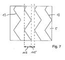
- the lightning discharge for example, clockwise, preferably on the protective housing 5 is arranged circumferentially and then merges at a certain height in an opposing helical or helical structure. If such a change occurs more frequently, it is possible to speak of a zigzag structure, as is explained with reference to FIGS. 6 and 7, for example.
- the first lightning conductor 17a is zigzag-shaped from top to bottom. The same applies to the lightning discharge 17b, 17c and 17d.
- FIG. 1 In this case, four are in the embodiment of FIG shown from top to bottom leading leads 17a to 17d, which are each aligned in pairs in opposite directions, touching each other at their coupling points 107 facing each other.
- the embodiment is therefore chosen as if a clockwise and a left-handed helix (here with the same pitch) are provided, which touch each other at the coupling points 107.
- the zigzag derivatives could also be separated at their coupling points and arranged laterally further apart.
- the lightning conductors could also be designed sinusoidally running from top to bottom. Mixed forms between a sinusoidal and a zigzag structure are also conceivable.
- the lightning conductors have a double function. On the one hand, they serve as lightning conductors and on the other hand they are intended to provide protection against lateral impacts. They are therefore often referred to in the literature as a guide.
Landscapes
- Details Of Aerials (AREA)
- Elimination Of Static Electricity (AREA)
- Emergency Protection Circuit Devices (AREA)
Claims (12)
- Parafoudre pour installations d'antennes, comportant plusieurs antennes rayonnantes ou agencements d'antennes rayonnantes (3) disposés en décalage en direction verticale, comportant une structure (1) portante, présentant les caractéristiques suivantes :- il est prévu un dispositif parafoudre,- le dispositif parafoudre comprend des lignes de parafoudre (17) s'étendant de haut en bas vers un potentiel de masse (15),caractérisé par les autres caractéristiques suivantes :- vue de côté, ladite au moins une ligne de parafoudre (17) s'étendant de haut en bas ou des tronçons individuels de celle-ci est/sont orientée(s) en angle par rapport à la verticale par le fait que la ligne de parafoudre (17) ou des tronçons individuels de celle-ci s'étendent sous forme d'hélice, de spirale, de vis, de zigzag et/ou sous forme sinusoïdale.
- Parafoudre selon la revendication 1, caractérisé en ce que ladite au moins une ligne de parafoudre (17) ou des tronçons de celle-ci est/sont agencée(s) sous un angle d'inclinaison α qui est supérieur à 20° et inférieur à 87°, de préférence supérieur à 40° et inférieur à 70°.
- Parafoudre selon la revendication 1 ou 2, caractérisé en ce qu'au moins deux lignes de parafoudre sous forme d'hélice, de spirale ou de vis sont prévues avec un décalage de 180° l'une par rapport aux autres.
- Parafoudre selon la revendication 1 ou 2, caractérisé en ce que les lignes de parafoudre (17) sont réalisées sous forme de spirale en vue de dessus axiale et s'étendent ici sur une hauteur axiale.
- Parafoudre selon l'une des revendications 1 à 4, caractérisé en ce qu'il est prévu au moins une ligne de parafoudre (17) qui, vue latéralement passe en s'étendant depuis le haut vers le bas d'une structure sous forme d'hélice, de spirale ou de vis dextrogyre en une structure lévogyre ou inversement.
- Parafoudre selon la revendication 5, caractérisé en ce qu'il est prévu au moins une ligne de parafoudre qui, en vue latérale, est réalisée en s'étendant en va-et-vient depuis le haut vers le bas sous forme de zigzag ou sous forme sinusoïdale ou sous une forme mixte de ces formes.
- Parafoudre selon l'une des revendications 1 à 6, caractérisé en ce que celui-ci est prévu pour des installations d'antennes qui comprennent des antennes rayonnantes ou des structures d'antennes rayonnantes (3) à polarisation horizontale.
- Parafoudre selon l'une des revendications 1 à 7, caractérisé en ce que celui-ci est prévu pour des installations d'antennes qui comprennent des agencements d'antennes à polarisation horizontale, des agencements d'antennes à polarisation verticale et/ou des agencements d'antennes (3) à polarisation circulaire.
- Parafoudre selon l'une des revendications 1 à 8, caractérisé en ce que la ligne de parafoudre (17), qui s'étend sous forme de zigzag et/ou sous forme sinusoïdale ou d'autre manière quelconque depuis le haut vers le bas en va et vient, est agencée en direction périphérique de l'agencement d'antennes en étant mutuellement décalée au moins deux fois, de préférence trois fois ou quatre fois.
- Parafoudre selon l'une des revendications 1 à 9, caractérisé en ce que l'installation d'antenne comprend des antennes rayonnantes et des structures d'antennes rayonnantes qui sont prévues en particulier pour fonctionner en mode TNT.
- Parafoudre selon l'une des revendications 1 à 10, caractérisé en ce qu'il est prévu un boîtier de protection (5), de préférence de forme cylindrique et entourant les antennes rayonnantes ou des structures d'antennes rayonnantes (3'), en matériau laissant passer les rayons électromagnétiques.
- Parafoudre selon l'une des revendications 1 à 10, caractérisé en ce que les lignes de parafoudre (17) sont reliées mécaniquement au boîtier de protection (5).
Priority Applications (1)
| Application Number | Priority Date | Filing Date | Title |
|---|---|---|---|
| SI200430516T SI1548874T1 (sl) | 2003-12-23 | 2004-07-08 | Zascita pred strelo za antenske naprave |
Applications Claiming Priority (2)
| Application Number | Priority Date | Filing Date | Title |
|---|---|---|---|
| DE20319983U | 2003-12-23 | ||
| DE20319983U DE20319983U1 (de) | 2003-12-23 | 2003-12-23 | Blitzschutz für Antennenanlagen |
Publications (2)
| Publication Number | Publication Date |
|---|---|
| EP1548874A1 EP1548874A1 (fr) | 2005-06-29 |
| EP1548874B1 true EP1548874B1 (fr) | 2007-10-31 |
Family
ID=32892539
Family Applications (1)
| Application Number | Title | Priority Date | Filing Date |
|---|---|---|---|
| EP04016127A Expired - Lifetime EP1548874B1 (fr) | 2003-12-23 | 2004-07-08 | Parafoudre pour les dispositifs d'antenne |
Country Status (6)
| Country | Link |
|---|---|
| EP (1) | EP1548874B1 (fr) |
| AT (1) | ATE377262T1 (fr) |
| AU (1) | AU2004205190B2 (fr) |
| DE (2) | DE20319983U1 (fr) |
| ES (1) | ES2294401T3 (fr) |
| SI (1) | SI1548874T1 (fr) |
Families Citing this family (4)
| Publication number | Priority date | Publication date | Assignee | Title |
|---|---|---|---|---|
| DE102010053639B4 (de) * | 2010-12-07 | 2017-05-18 | Rohde & Schwarz Gmbh & Co. Kg | Blitzfangstab für Antennensysteme |
| CN113898235A (zh) * | 2021-08-30 | 2022-01-07 | 张新磊 | 一种用于5g通信的网络通讯塔 |
| CN113675579B (zh) * | 2021-08-31 | 2024-01-19 | 国网河南省电力公司经济技术研究院 | 一种安装5g天线的变电站构支架装置 |
| CN119381756B (zh) * | 2024-12-27 | 2025-03-07 | 湖南湘银河传感科技有限公司 | 防雷型gnss扼流圈天线 |
Family Cites Families (11)
| Publication number | Priority date | Publication date | Assignee | Title |
|---|---|---|---|---|
| DE842664C (de) * | 1950-09-03 | 1952-06-30 | Siemens Ag | Blitzschutz fuer an geerdeten Traegern befestigte Strahler |
| US2985878A (en) * | 1952-02-13 | 1961-05-23 | Gen Electric | Wound antenna with conductive support |
| GB943779A (en) * | 1961-05-10 | 1963-12-04 | Siemens Ag | Improvements in aerials |
| DE1297707B (de) * | 1962-06-29 | 1969-06-19 | Rohde & Schwarz | Antennenanordnung bestehend aus je einer Antenne fuer horizontal und vertikal polarisierte Abstrahlung |
| US4287520A (en) * | 1979-11-09 | 1981-09-01 | The United States Of America As Represented By The Secretary Of The Air Force | Slot chevron element for periodic antennas and radomes |
| JP2544440B2 (ja) * | 1988-04-30 | 1996-10-16 | 富士通株式会社 | 絶縁体成形の導波管を用いた避雷構造 |
| FR2634598B1 (fr) * | 1988-07-22 | 1990-10-05 | Thomson Lgt | Antenne omnidirectionnelle, notamment pour l'emission de signaux de radiodiffusion ou de television dans la bande des ondes decimetriques, et systeme rayonnant forme d'un groupement de ces antennes |
| DE19615213B4 (de) * | 1996-04-18 | 2005-10-06 | Deutsche Telekom Ag | Fernsteuerbare Miniaturhebebühne |
| US5930100A (en) * | 1996-10-31 | 1999-07-27 | Marilyn A. Gasque | Lightning retardant cable |
| JP3634244B2 (ja) * | 2000-06-30 | 2005-03-30 | 三菱電機株式会社 | 誘雷装置及びその誘雷導体部の配置方法 |
| US7068233B2 (en) * | 2002-05-06 | 2006-06-27 | Db Systems, Inc. | Integrated multipath limiting ground based antenna |
-
2003
- 2003-12-23 DE DE20319983U patent/DE20319983U1/de not_active Expired - Lifetime
-
2004
- 2004-07-08 AT AT04016127T patent/ATE377262T1/de not_active IP Right Cessation
- 2004-07-08 ES ES04016127T patent/ES2294401T3/es not_active Expired - Lifetime
- 2004-07-08 SI SI200430516T patent/SI1548874T1/sl unknown
- 2004-07-08 EP EP04016127A patent/EP1548874B1/fr not_active Expired - Lifetime
- 2004-07-08 DE DE502004005354T patent/DE502004005354D1/de not_active Expired - Fee Related
- 2004-08-23 AU AU2004205190A patent/AU2004205190B2/en not_active Ceased
Also Published As
| Publication number | Publication date |
|---|---|
| DE20319983U1 (de) | 2004-08-19 |
| ATE377262T1 (de) | 2007-11-15 |
| EP1548874A1 (fr) | 2005-06-29 |
| DE502004005354D1 (de) | 2007-12-13 |
| ES2294401T3 (es) | 2008-04-01 |
| AU2004205190B2 (en) | 2009-03-05 |
| AU2004205190A1 (en) | 2005-07-07 |
| SI1548874T1 (sl) | 2008-02-29 |
Similar Documents
| Publication | Publication Date | Title |
|---|---|---|
| DE60034042T2 (de) | Rahmenantenne mit vier resonanzfrequenzen | |
| EP2340584B1 (fr) | Antenne à bande large | |
| DE69812776T2 (de) | Wendelantenne mit variabler Länge | |
| EP3025394B1 (fr) | Antenne omnidirectionnelle à large bande | |
| EP1095426B1 (fr) | Antenne a plusieurs plages de frequence | |
| EP1695417B1 (fr) | Antenne comportant au moins un dipole ou un ensemble rayonnant semblable a un dipole | |
| DE102005015561A1 (de) | Interne Breitbandantenne | |
| EP1470615A1 (fr) | Ensemble antenne rayonnante a double polarisation | |
| DE102010011867A1 (de) | Breitbandige omnidirektionale Antenne | |
| DE102005005781A1 (de) | Radom, insbesondere für Mobilfunkantennen sowie zugehörige Mobilfunkantenne | |
| EP1695416B1 (fr) | Antenne a large bande, notamment antenne omnidirectionnelle | |
| DE3118988A1 (de) | "antenne" | |
| DE10359623A1 (de) | Mobilfunk-Antennenanordnung für eine Basisstation | |
| EP1548874B1 (fr) | Parafoudre pour les dispositifs d'antenne | |
| DE102012108600B3 (de) | Antennenanordnung mit flachbauendem Antennenelement | |
| EP0933833B1 (fr) | Radiateur à guide d'ondes | |
| EP1056155B1 (fr) | Antenne pour mobile en particulier pour véhicule comprenant au moins une polarisation circulaire et une polarisation linéaire, de préférence verticale | |
| DE102016121335B4 (de) | Magnetantenne mit verringerten Verlusten und Verwendung derselben | |
| DE10239874B3 (de) | Antennensystem für mehrere Frequenzbereiche | |
| DE69212964T2 (de) | Kurzwellendipol und Drehantenne mit derartigen Dipolen | |
| DE68920494T2 (de) | Breitband-Empfangsantenne. | |
| DE3821529C2 (fr) | ||
| EP2756550B1 (fr) | Antenne multibande pour véhicule automobile | |
| DE3822081C2 (fr) | ||
| DE1297707B (de) | Antennenanordnung bestehend aus je einer Antenne fuer horizontal und vertikal polarisierte Abstrahlung |
Legal Events
| Date | Code | Title | Description |
|---|---|---|---|
| PUAI | Public reference made under article 153(3) epc to a published international application that has entered the european phase |
Free format text: ORIGINAL CODE: 0009012 |
|
| AK | Designated contracting states |
Kind code of ref document: A1 Designated state(s): AT BE BG CH CY CZ DE DK EE ES FI FR GB GR HU IE IT LI LU MC NL PL PT RO SE SI SK TR |
|
| AX | Request for extension of the european patent |
Extension state: AL HR LT LV MK |
|
| 17P | Request for examination filed |
Effective date: 20050908 |
|
| AKX | Designation fees paid |
Designated state(s): AT BE BG CH CY CZ DE DK EE ES FI FR GB GR HU IE IT LI LU MC NL PL PT RO SE SI SK TR |
|
| 17Q | First examination report despatched |
Effective date: 20060117 |
|
| GRAP | Despatch of communication of intention to grant a patent |
Free format text: ORIGINAL CODE: EPIDOSNIGR1 |
|
| GRAS | Grant fee paid |
Free format text: ORIGINAL CODE: EPIDOSNIGR3 |
|
| GRAA | (expected) grant |
Free format text: ORIGINAL CODE: 0009210 |
|
| AK | Designated contracting states |
Kind code of ref document: B1 Designated state(s): AT BE BG CH CY CZ DE DK EE ES FI FR GB GR HU IE IT LI LU MC NL PL PT RO SE SI SK TR |
|
| REG | Reference to a national code |
Ref country code: GB Ref legal event code: FG4D Free format text: NOT ENGLISH |
|
| REG | Reference to a national code |
Ref country code: IE Ref legal event code: FG4D Free format text: LANGUAGE OF EP DOCUMENT: GERMAN |
|
| REG | Reference to a national code |
Ref country code: CH Ref legal event code: EP |
|
| REF | Corresponds to: |
Ref document number: 502004005354 Country of ref document: DE Date of ref document: 20071213 Kind code of ref document: P |
|
| NLV1 | Nl: lapsed or annulled due to failure to fulfill the requirements of art. 29p and 29m of the patents act | ||
| REG | Reference to a national code |
Ref country code: ES Ref legal event code: FG2A Ref document number: 2294401 Country of ref document: ES Kind code of ref document: T3 |
|
| PG25 | Lapsed in a contracting state [announced via postgrant information from national office to epo] |
Ref country code: SE Free format text: LAPSE BECAUSE OF FAILURE TO SUBMIT A TRANSLATION OF THE DESCRIPTION OR TO PAY THE FEE WITHIN THE PRESCRIBED TIME-LIMIT Effective date: 20080131 Ref country code: NL Free format text: LAPSE BECAUSE OF FAILURE TO SUBMIT A TRANSLATION OF THE DESCRIPTION OR TO PAY THE FEE WITHIN THE PRESCRIBED TIME-LIMIT Effective date: 20071031 |
|
| GBV | Gb: ep patent (uk) treated as always having been void in accordance with gb section 77(7)/1977 [no translation filed] | ||
| PG25 | Lapsed in a contracting state [announced via postgrant information from national office to epo] |
Ref country code: PT Free format text: LAPSE BECAUSE OF FAILURE TO SUBMIT A TRANSLATION OF THE DESCRIPTION OR TO PAY THE FEE WITHIN THE PRESCRIBED TIME-LIMIT Effective date: 20080331 Ref country code: BG Free format text: LAPSE BECAUSE OF FAILURE TO SUBMIT A TRANSLATION OF THE DESCRIPTION OR TO PAY THE FEE WITHIN THE PRESCRIBED TIME-LIMIT Effective date: 20080131 Ref country code: PL Free format text: LAPSE BECAUSE OF FAILURE TO SUBMIT A TRANSLATION OF THE DESCRIPTION OR TO PAY THE FEE WITHIN THE PRESCRIBED TIME-LIMIT Effective date: 20071031 |
|
| REG | Reference to a national code |
Ref country code: IE Ref legal event code: FD4D |
|
| PG25 | Lapsed in a contracting state [announced via postgrant information from national office to epo] |
Ref country code: DK Free format text: LAPSE BECAUSE OF FAILURE TO SUBMIT A TRANSLATION OF THE DESCRIPTION OR TO PAY THE FEE WITHIN THE PRESCRIBED TIME-LIMIT Effective date: 20071031 |
|
| EN | Fr: translation not filed | ||
| PG25 | Lapsed in a contracting state [announced via postgrant information from national office to epo] |
Ref country code: SK Free format text: LAPSE BECAUSE OF FAILURE TO SUBMIT A TRANSLATION OF THE DESCRIPTION OR TO PAY THE FEE WITHIN THE PRESCRIBED TIME-LIMIT Effective date: 20071031 Ref country code: RO Free format text: LAPSE BECAUSE OF FAILURE TO SUBMIT A TRANSLATION OF THE DESCRIPTION OR TO PAY THE FEE WITHIN THE PRESCRIBED TIME-LIMIT Effective date: 20071031 |
|
| PLBE | No opposition filed within time limit |
Free format text: ORIGINAL CODE: 0009261 |
|
| STAA | Information on the status of an ep patent application or granted ep patent |
Free format text: STATUS: NO OPPOSITION FILED WITHIN TIME LIMIT |
|
| 26N | No opposition filed |
Effective date: 20080801 |
|
| PG25 | Lapsed in a contracting state [announced via postgrant information from national office to epo] |
Ref country code: FR Free format text: LAPSE BECAUSE OF FAILURE TO SUBMIT A TRANSLATION OF THE DESCRIPTION OR TO PAY THE FEE WITHIN THE PRESCRIBED TIME-LIMIT Effective date: 20080704 Ref country code: IE Free format text: LAPSE BECAUSE OF FAILURE TO SUBMIT A TRANSLATION OF THE DESCRIPTION OR TO PAY THE FEE WITHIN THE PRESCRIBED TIME-LIMIT Effective date: 20071031 |
|
| PG25 | Lapsed in a contracting state [announced via postgrant information from national office to epo] |
Ref country code: GB Free format text: LAPSE BECAUSE OF FAILURE TO SUBMIT A TRANSLATION OF THE DESCRIPTION OR TO PAY THE FEE WITHIN THE PRESCRIBED TIME-LIMIT Effective date: 20071031 |
|
| PG25 | Lapsed in a contracting state [announced via postgrant information from national office to epo] |
Ref country code: GR Free format text: LAPSE BECAUSE OF FAILURE TO SUBMIT A TRANSLATION OF THE DESCRIPTION OR TO PAY THE FEE WITHIN THE PRESCRIBED TIME-LIMIT Effective date: 20080201 |
|
| PG25 | Lapsed in a contracting state [announced via postgrant information from national office to epo] |
Ref country code: FI Free format text: LAPSE BECAUSE OF FAILURE TO SUBMIT A TRANSLATION OF THE DESCRIPTION OR TO PAY THE FEE WITHIN THE PRESCRIBED TIME-LIMIT Effective date: 20071031 |
|
| REG | Reference to a national code |
Ref country code: CH Ref legal event code: PL |
|
| PG25 | Lapsed in a contracting state [announced via postgrant information from national office to epo] |
Ref country code: MC Free format text: LAPSE BECAUSE OF NON-PAYMENT OF DUE FEES Effective date: 20080731 |
|
| PG25 | Lapsed in a contracting state [announced via postgrant information from national office to epo] |
Ref country code: EE Free format text: LAPSE BECAUSE OF FAILURE TO SUBMIT A TRANSLATION OF THE DESCRIPTION OR TO PAY THE FEE WITHIN THE PRESCRIBED TIME-LIMIT Effective date: 20071031 |
|
| PG25 | Lapsed in a contracting state [announced via postgrant information from national office to epo] |
Ref country code: LI Free format text: LAPSE BECAUSE OF NON-PAYMENT OF DUE FEES Effective date: 20080731 Ref country code: CH Free format text: LAPSE BECAUSE OF NON-PAYMENT OF DUE FEES Effective date: 20080731 |
|
| PG25 | Lapsed in a contracting state [announced via postgrant information from national office to epo] |
Ref country code: CY Free format text: LAPSE BECAUSE OF FAILURE TO SUBMIT A TRANSLATION OF THE DESCRIPTION OR TO PAY THE FEE WITHIN THE PRESCRIBED TIME-LIMIT Effective date: 20071031 |
|
| PG25 | Lapsed in a contracting state [announced via postgrant information from national office to epo] |
Ref country code: AT Free format text: LAPSE BECAUSE OF NON-PAYMENT OF DUE FEES Effective date: 20080708 |
|
| PGFP | Annual fee paid to national office [announced via postgrant information from national office to epo] |
Ref country code: DE Payment date: 20090923 Year of fee payment: 6 |
|
| PG25 | Lapsed in a contracting state [announced via postgrant information from national office to epo] |
Ref country code: HU Free format text: LAPSE BECAUSE OF FAILURE TO SUBMIT A TRANSLATION OF THE DESCRIPTION OR TO PAY THE FEE WITHIN THE PRESCRIBED TIME-LIMIT Effective date: 20080501 Ref country code: LU Free format text: LAPSE BECAUSE OF NON-PAYMENT OF DUE FEES Effective date: 20080708 Ref country code: BE Free format text: LAPSE BECAUSE OF NON-PAYMENT OF DUE FEES Effective date: 20080731 |
|
| PG25 | Lapsed in a contracting state [announced via postgrant information from national office to epo] |
Ref country code: TR Free format text: LAPSE BECAUSE OF FAILURE TO SUBMIT A TRANSLATION OF THE DESCRIPTION OR TO PAY THE FEE WITHIN THE PRESCRIBED TIME-LIMIT Effective date: 20071031 |
|
| PG25 | Lapsed in a contracting state [announced via postgrant information from national office to epo] |
Ref country code: IT Free format text: LAPSE BECAUSE OF NON-PAYMENT OF DUE FEES Effective date: 20080731 |
|
| PG25 | Lapsed in a contracting state [announced via postgrant information from national office to epo] |
Ref country code: DE Free format text: LAPSE BECAUSE OF NON-PAYMENT OF DUE FEES Effective date: 20110201 |
|
| REG | Reference to a national code |
Ref country code: DE Ref legal event code: R119 Ref document number: 502004005354 Country of ref document: DE Effective date: 20110201 |
|
| PGFP | Annual fee paid to national office [announced via postgrant information from national office to epo] |
Ref country code: CZ Payment date: 20140625 Year of fee payment: 11 |
|
| PGFP | Annual fee paid to national office [announced via postgrant information from national office to epo] |
Ref country code: ES Payment date: 20140721 Year of fee payment: 11 Ref country code: SI Payment date: 20140701 Year of fee payment: 11 |
|
| PG25 | Lapsed in a contracting state [announced via postgrant information from national office to epo] |
Ref country code: CZ Free format text: LAPSE BECAUSE OF NON-PAYMENT OF DUE FEES Effective date: 20150708 |
|
| REG | Reference to a national code |
Ref country code: SI Ref legal event code: KO00 Effective date: 20160331 |
|
| PG25 | Lapsed in a contracting state [announced via postgrant information from national office to epo] |
Ref country code: SI Free format text: LAPSE BECAUSE OF NON-PAYMENT OF DUE FEES Effective date: 20150709 |
|
| REG | Reference to a national code |
Ref country code: ES Ref legal event code: FD2A Effective date: 20160826 |
|
| PG25 | Lapsed in a contracting state [announced via postgrant information from national office to epo] |
Ref country code: ES Free format text: LAPSE BECAUSE OF NON-PAYMENT OF DUE FEES Effective date: 20150709 |