EP1548708A1 - Magnetkopf und magnetaufzeichnungs-/-wiedergabeeinrichtung - Google Patents
Magnetkopf und magnetaufzeichnungs-/-wiedergabeeinrichtung Download PDFInfo
- Publication number
- EP1548708A1 EP1548708A1 EP03792787A EP03792787A EP1548708A1 EP 1548708 A1 EP1548708 A1 EP 1548708A1 EP 03792787 A EP03792787 A EP 03792787A EP 03792787 A EP03792787 A EP 03792787A EP 1548708 A1 EP1548708 A1 EP 1548708A1
- Authority
- EP
- European Patent Office
- Prior art keywords
- magnetic
- multilayer film
- denotes
- magnetic head
- films
- Prior art date
- Legal status (The legal status is an assumption and is not a legal conclusion. Google has not performed a legal analysis and makes no representation as to the accuracy of the status listed.)
- Withdrawn
Links
Images


Classifications
-
- G—PHYSICS
- G11—INFORMATION STORAGE
- G11B—INFORMATION STORAGE BASED ON RELATIVE MOVEMENT BETWEEN RECORD CARRIER AND TRANSDUCER
- G11B5/00—Recording by magnetisation or demagnetisation of a record carrier; Reproducing by magnetic means; Record carriers therefor
- G11B5/127—Structure or manufacture of heads, e.g. inductive
- G11B5/187—Structure or manufacture of the surface of the head in physical contact with, or immediately adjacent to the recording medium; Pole pieces; Gap features
- G11B5/1875—"Composite" pole pieces, i.e. poles composed in some parts of magnetic particles and in some other parts of magnetic metal layers
- G11B5/1877—"Composite" pole pieces, i.e. poles composed in some parts of magnetic particles and in some other parts of magnetic metal layers including at least one magnetic thin film
- G11B5/1878—"Composite" pole pieces, i.e. poles composed in some parts of magnetic particles and in some other parts of magnetic metal layers including at least one magnetic thin film disposed immediately adjacent to the transducing gap, e.g. "Metal-In-Gap" structure
-
- G—PHYSICS
- G11—INFORMATION STORAGE
- G11B—INFORMATION STORAGE BASED ON RELATIVE MOVEMENT BETWEEN RECORD CARRIER AND TRANSDUCER
- G11B5/00—Recording by magnetisation or demagnetisation of a record carrier; Reproducing by magnetic means; Record carriers therefor
- G11B5/127—Structure or manufacture of heads, e.g. inductive
- G11B5/1274—Structure or manufacture of heads, e.g. inductive with "composite" cores, i.e. cores composed in some parts of magnetic particles and in some other parts of magnetic metal layers
- G11B5/1276—Structure or manufacture of heads, e.g. inductive with "composite" cores, i.e. cores composed in some parts of magnetic particles and in some other parts of magnetic metal layers including at least one magnetic thin film
-
- G—PHYSICS
- G11—INFORMATION STORAGE
- G11B—INFORMATION STORAGE BASED ON RELATIVE MOVEMENT BETWEEN RECORD CARRIER AND TRANSDUCER
- G11B5/00—Recording by magnetisation or demagnetisation of a record carrier; Reproducing by magnetic means; Record carriers therefor
- G11B5/008—Recording on, or reproducing or erasing from, magnetic tapes, sheets, e.g. cards, or wires
- G11B5/00813—Recording on, or reproducing or erasing from, magnetic tapes, sheets, e.g. cards, or wires magnetic tapes
- G11B5/00847—Recording on, or reproducing or erasing from, magnetic tapes, sheets, e.g. cards, or wires magnetic tapes on transverse tracks
- G11B5/0086—Recording on, or reproducing or erasing from, magnetic tapes, sheets, e.g. cards, or wires magnetic tapes on transverse tracks using cyclically driven heads providing segmented tracks
-
- G—PHYSICS
- G11—INFORMATION STORAGE
- G11B—INFORMATION STORAGE BASED ON RELATIVE MOVEMENT BETWEEN RECORD CARRIER AND TRANSDUCER
- G11B5/00—Recording by magnetisation or demagnetisation of a record carrier; Reproducing by magnetic means; Record carriers therefor
- G11B5/02—Recording, reproducing, or erasing methods; Read, write or erase circuits therefor
-
- G—PHYSICS
- G11—INFORMATION STORAGE
- G11B—INFORMATION STORAGE BASED ON RELATIVE MOVEMENT BETWEEN RECORD CARRIER AND TRANSDUCER
- G11B5/00—Recording by magnetisation or demagnetisation of a record carrier; Reproducing by magnetic means; Record carriers therefor
- G11B5/48—Disposition or mounting of heads or head supports relative to record carriers ; arrangements of heads, e.g. for scanning the record carrier to increase the relative speed
- G11B5/52—Disposition or mounting of heads or head supports relative to record carriers ; arrangements of heads, e.g. for scanning the record carrier to increase the relative speed with simultaneous movement of head and record carrier, e.g. rotation of head
- G11B5/53—Disposition or mounting of heads on rotating support
Definitions
- the present invention relates to a magnetic head for high-density recording that has an excellent property at high frequencies and relates to a magnetic recording/reproducing device provided with the magnetic head.
- a magnetic head including a metal magnetic film having a high saturation flux density and a high magnetic permeability provided close to a gap has been put to practical use in order to allow for sufficient recording/reproducing properties with respect to a magnetic medium having a high coercive force.
- the transfer rate of signals should be raised, and therefore still higher-frequency properties are currently demanded.
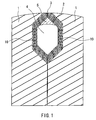
- a magnetic head having a cross-sectional configuration as shown in Fig. 1 has been proposed conventionally (Japanese Patent No. 2959908).
- Fig. 9 is an enlarged view of a portion around a gap of this magnetic head.
- This magnetic head is configured as follows: a magnetic metal film 8 and a non-magnetic layer 9 such as SiO 2 or Al 2 O 3 are alternately formed by sputtering or the like on a substrate 1 to form a laminated film, the substrate 1 being made of a magnetic oxide or being non-magnetic, in which a winding window 10 is formed. Subsequently, a gap member having a predetermined thickness is deposited for forming a gap 3, and then magnetic cores are bonded via the gap by glass or the like so as to be integrated.
- Reference numeral 5 denotes a welded glass.
- Fig. 2 shows one example of a configuration of a surface at which a magnetic head slides with respect to a magnetic medium.
- reference numeral 2 denotes a magnetic multilayer film constituting a core of the magnetic head
- 4 denotes a winding window of the magnetic head
- 6 denotes a welded glass
- 7 denotes an interface between the substrate 1 and the magnetic multilayer film 2
- 10 denotes a groove for forming the winding window
- 12 denotes an azimuth angle.
- the gap 3 is parallel with the interface 7 between the metal magnetic multilayer film and the substrate 1, and the respective non-magnetic layers 9 also are parallel with the gap 3.
- the respective non-magnetic layers that are parallel with the gap function as a pseudo gap, so that a pseudo signal is superimposed and a distortion occurs in a reproduced signal, thus increasing noise.
- a magnetic recording/reproducing device provided with such a magnetic head having a pseudo signal has a problem of degradation of S/N.
- a multilayer film is disposed including metal magnetic films and non-magnetic films that are alternately laminated, and a boundary between the multilayer film and a magnetic oxide substrate or a non-magnetic substrate on which the multilayer film is to be formed is parallel with a gap section at a surface of the magnetic head for sliding with respect to a magnetic recording medium.
- the metal magnetic films constituting the multilayer film have two or more types of thickness, or the metal magnetic films constituting the multilayer film have a uniform thickness, and the uniform thickness t satisfies t ⁇ v ⁇ cos ⁇ / fmax, where v denotes a relative speed of the head to the recording medium, fmax denotes an upper limit of frequencies to be used and ⁇ denotes an azimuth angle.
- a magnetic recording/reproducing device of the present invention is provided with a magnetic head, in which a multilayer film is disposed, the multilayer film including metal magnetic films and non-magnetic films that are alternately laminated, and a boundary between the multilayer film and a magnetic oxide substrate or a non-magnetic substrate on which the multilayer film is to be formed is parallel with a gap section at a surface of the magnetic head for sliding with respect to a magnetic recording medium.
- the metal magnetic films constituting the multilayer film have two or more types of thickness, or the metal magnetic films constituting the multilayer film have a uniform thickness, and the uniform thickness t satisfies t ⁇ v ⁇ cos ⁇ / fmax, where v denotes a relative speed of the head to the recording medium, fmax denotes an upper limit of frequencies to be used and ⁇ denotes an azimuth angle.
- a multilayer film is configured by laminating metal magnetic layers having a uniform thickness.
- a multilayer film is configured by laminating metal magnetic layers having different thicknesses or by making the thickness of the metal magnetic films constituting the multilayer film uniform.
- this thickness t satisfies t ⁇ v ⁇ cos ⁇ / fmax, where v denotes a relative speed of the head to the recording medium, fmax denotes an upper limit of frequencies to be used and ⁇ denotes an azimuth angle, whereby a pseudo signal can be suppressed and noise can be reduced.
- a magnetic recording/reproducing device of the present invention is provided with a magnetic head including metal magnetic films constituting the multilayer film having two or more types of thickness, or the metal magnetic films constituting the multilayer film having a thickness t satisfying t ⁇ v ⁇ cos ⁇ / f, whereby the magnetic recording/reproducing device can be substantially free from the influence of pseudo signals of the magnetic head.
- the difference in thicknesses of the metal magnetic films is less than 5%, a remarkable effect of reducing a pseudo signal cannot be observed, so that it is preferable that the difference in thicknesses is 5% or more.
- the metal magnetic films constituting the multilayer film have thicknesses varied within a range of 100 nm to 2000 nm.
- the metal magnetic films constituting the multilayer film have a uniform thickness within a range of 100 nm to 2000 nm.
- T denotes at least one element selected from the group consisting of Fe, Co and Ni
- M denotes at least one element selected from the group constituting of Nb, Zr, Ti, Ta, Hf, Cr, Mo, W and Mn
- X denotes at least one element
- the non-magnetic films include an oxide of Si, Al, Ti, Cr or Ta.
- the substrate includes: magnetic Mn-Zn ferrite single crystal; non-magnetic ferrite single crystal; ⁇ -hematite; calcium titanate or magnesium titanate.
- Mn-Zn ferrite single crystal was used as a substrate 1.
- a groove 10 for forming a winding window 4 was formed using a grinding stone.
- Fig. 4 which is an enlarged view of a portion around a gap, FeTaN films 8 and SiO 2 films 9 as non-magnetic layers were alternately formed on the above Mn-Zn ferrite single crystal so as to form a laminated film 2, where the FeTaN films 8 were formed by sputtering in a mixed gas of Ar gas and N 2 (nitrogen) gas using a Fe-Ta target, and the SiO 2 films 9 were formed in Ar gas.
- the thicknesses of the FeTaN films 8 as the magnetic multilayer film included two types of 0.5 ⁇ m and 1 ⁇ m, which were alternately laminated.
- the thickness of a SiO 2 film 9 was 10 nm.
- the overall film thickness was about 6 ⁇ m.
- a gap member was deposited for forming a gap 3 and core halves were bonded so as to sandwich the gap 3 therebetween.
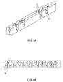
- grooves 11 for forming tracks were manufactured with respect to the thus bonded core using a grinding stone, which was then cut into chips to have the gradient of an azimuth angle 12 relative to the gap as shown in Fig. 8B, whereby a magnetic head was prepared.
- a configuration of the surface for sliding with respect to the magnetic medium was as shown in Fig. 2.
- a magnetic head was formed similarly, where when the magnetic multilayer film 2 was formed, the thickness of FeTaSiN films 8 as the magnetic films was made constant at 0.5 ⁇ m and the thickness of the SiO 2 films 9 as the non-magnetic layers was set at 10 nm as shown in Fig. 10, so that the overall film thickness of the laminated film was about 6 ⁇ m. Except for the configuration of the magnetic multilayer film of Fig. 10, this magnetic head had the same configuration as that of the magnetic head of the above-described embodiment.
- Fig. 11 schematically shows a configuration of a magnetic recording/reproducing device including a drum unit, which is provided with a magnetic head according to one embodiment of the present invention.
- a drum unit 23 for performing recording/reproducing with respect to a magnetic tape 24 is provided with magnetic heads 21 and 22 having mutually different azimuth angles.
- the tape 24 is guided by guideposts 25 to 30 while by using a capstan 31 and a pinch roller 32 so as to be supplied from a feeding reel 34 of a cassette 33 to a takeup reel 35 by way of the drum unit 23.
- the magnetic tape 24 is wound around the drum unit 23 rotating at high speed, recording and reproducing are performed with respect to the magnetic tape 24 using the magnetic heads 21 and 22.
- Non-magnetic ferrite single crystal was used as a substrate 1.
- a groove 10 for forming a winding window 4 was formed using a grinding stone.
- Fig. 3 which is an enlarged view of a portion around a gap, FeTaN films 8 and Al 2 O 3 films 9 as non-magnetic layers were formed alternately on the above non-magnetic ferrite single crystal so as to form a laminated film 2, where the FeTaN films 8 were formed by sputtering in a mixture gas of Ar gas and N 2 (nitrogen) gas using a Fe-Ta target, and the Al 2 O 3 films 9 were formed in Ar gas.
- the FeTaN films 8 as the magnetic multilayer film were laminated so that the thickness increased gradually by 0.05 ⁇ m. More specifically, the first layer had a thickness of 0.5 ⁇ m, the second layer had a thickness of 0.55 ⁇ m, the third layer had a thickness of 0.60 ⁇ m ... The thickness of an Al 2 O 3 film 9 was 5 nm. The overall film thickness was about 20 ⁇ m.
- the surface in which a gap 3 was to be formed was ground by lapping so that the magnetic multilayer film 2 was left only in the winding window 4, and then a gap member was deposited and core halves were bonded so as to sandwich the gap 3 therebetween. As shown in Fig.
- grooves 11 for forming tracks were manufactured in the bonded cores using a grinding stone, which was then cut into chips to form the gradient of an azimuth angle 12 of 20° relative to the gap as shown in Fig. 8B, whereby a magnetic head was prepared.
- a configuration of the surface for sliding with respect to the magnetic medium was as shown in Fig. 2.
- a magnetic head was formed similarly, where when the magnetic multilayer film 2 was formed, the thickness of the FeTaN films 8 as the magnetic films was made constant at 0.5 ⁇ m and the thickness of the Al 2 O 3 films 9 as the non-magnetic layers was set at 5 nm as shown in Fig. 9, so that the overall film thickness was about 20 ⁇ m. Except for the configuration of the magnetic multilayer film of Fig. 9, this magnetic head had the same configuration as that of the magnetic head of the above-described embodiment.
- the non-magnetic ferrite single crystal substrate was used as the substrate, even when Mn-Zn ferrite as a magnetic substrate was used instead, the same effects as in the non-magnetic substrate could be obtained concerning the reduction of a pseudo signal by virtue of the configuration with different film thicknesses.
- Non-magnetic ferrite single crystal was used as a substrate 1. Firstly, as shown in Fig. 5, a groove 10 for forming a winding window 4 was formed using a grinding stone. Next, as shown in Fig. 6 and Fig. 9, which is an enlarged view of a portion around a gap, FeTaN films 8 and SiO 2 films 9 as non-magnetic layers were alternately formed on the above non-magnetic ferrite single crystal so as to form a laminated film 2, where the FeTaN films 8 were formed by sputtering in a mixture gas of Ar gas and N 2 (nitrogen) gas using a Fe-Ta target, and the SiO 2 films 9 were formed in Ar gas.
- the thickness of a FeTaN film 8 laminated as the magnetic multilayer film was made uniform.
- samples were prepared including the FeTaN films 8, one layer of the FeTaN films 8 of each sample being 0.25 ⁇ m, 0.5 ⁇ m, 1 ⁇ m and 2 ⁇ m in thickness, and the thickness of their SiO 2 films 9 was 5 nm.
- the overall film thickness was about 20 ⁇ m, which was common to all of the samples.
- the surface in which a gap 3 was to be formed was ground by lapping so that the magnetic multilayer film 2 was left only in the winding window 4, and then a gap member was deposited and core halves were bonded so as to sandwich the gap 3 therebetween.
- Fig. 7 the surface in which a gap 3 was to be formed was ground by lapping so that the magnetic multilayer film 2 was left only in the winding window 4, and then a gap member was deposited and core halves were bonded so as to sandwich the gap 3 therebetween.
- Relative speed 10.5m/s
- a magnetic recording/reproducing device may be provided with a magnetic head that satisfies fmax ⁇ v ⁇ cos ⁇ / t, where v denotes a relative speed of the magnetic head to a magnetic tape and fmax is the upper limit of frequencies to be used, whereby the magnetic recording/reproducing device can be substantially free from the influence of pseudo signals of the magnetic head.
- the magnetic head provided in the magnetic recording/reproducing device of the present embodiment adopts the non-magnetic ferrite as the substrate 1.
- the configuration including the magnetic multilayer film whose thickness of the magnetic film satisfies fmax ⁇ v ⁇ cos ⁇ / t enables the above-stated effect, that is, the magnetic recording/reproducing device can be substantially free from the influence of pseudo signals of the magnetic head.
- a pseudo signal can be suppressed, and noise can be reduced.
- a magnetic recording/reproducing device of the present invention can reduce the influence of a pseudo signal of a magnetic head to a substantially trivial level.
Landscapes
- Engineering & Computer Science (AREA)
- Manufacturing & Machinery (AREA)
- Magnetic Heads (AREA)
Applications Claiming Priority (3)
| Application Number | Priority Date | Filing Date | Title |
|---|---|---|---|
| JP2002242498 | 2002-08-22 | ||
| JP2002242498 | 2002-08-22 | ||
| PCT/JP2003/010601 WO2004019319A1 (ja) | 2002-08-22 | 2003-08-21 | 磁気ヘッドおよび磁気記録再生装置 |
Publications (2)
| Publication Number | Publication Date |
|---|---|
| EP1548708A1 true EP1548708A1 (de) | 2005-06-29 |
| EP1548708A4 EP1548708A4 (de) | 2008-08-27 |
Family
ID=31944020
Family Applications (1)
| Application Number | Title | Priority Date | Filing Date |
|---|---|---|---|
| EP03792787A Withdrawn EP1548708A4 (de) | 2002-08-22 | 2003-08-21 | Magnetkopf und magnetaufzeichnungs-/-wiedergabeeinrichtung |
Country Status (4)
| Country | Link |
|---|---|
| US (1) | US7304822B2 (de) |
| EP (1) | EP1548708A4 (de) |
| CN (1) | CN100470634C (de) |
| WO (1) | WO2004019319A1 (de) |
Families Citing this family (1)
| Publication number | Priority date | Publication date | Assignee | Title |
|---|---|---|---|---|
| JP7477505B2 (ja) * | 2018-11-15 | 2024-05-01 | ロジャーズ・コーポレイション | 高周波数磁気フィルム、その製造方法及び使用 |
Family Cites Families (10)
| Publication number | Priority date | Publication date | Assignee | Title |
|---|---|---|---|---|
| JPH07101483B2 (ja) * | 1983-08-29 | 1995-11-01 | ソニー株式会社 | 薄膜型磁気ヘッド |
| US5278716A (en) * | 1987-07-14 | 1994-01-11 | Sanyo Electric Co. | Magnetic head with suppressed generation of pseudogap |
| JPS6423411A (en) * | 1987-07-17 | 1989-01-26 | Mitsubishi Electric Corp | Magnetic head |
| JPS6423411U (de) | 1987-07-31 | 1989-02-08 | ||
| JP2959908B2 (ja) | 1992-03-02 | 1999-10-06 | アルプス電気株式会社 | 磁気ヘッド |
| JPH06338410A (ja) * | 1993-03-31 | 1994-12-06 | Matsushita Electric Ind Co Ltd | 軟磁性多層膜と磁気ヘッド |
| JPH07296321A (ja) | 1994-04-21 | 1995-11-10 | Hitachi Metals Ltd | 磁気ヘッド |
| JPH08147621A (ja) | 1994-11-21 | 1996-06-07 | Hitachi Denshi Ltd | 磁気ヘッド |
| JPH11120528A (ja) * | 1997-10-08 | 1999-04-30 | Tdk Corp | 磁気ヘッド |
| US6717770B1 (en) * | 2000-03-24 | 2004-04-06 | Seagate Technology Llc | Recording head for applying a magnetic field perpendicular to the magnetizations within magnetic storage media |
-
2003
- 2003-08-21 EP EP03792787A patent/EP1548708A4/de not_active Withdrawn
- 2003-08-21 WO PCT/JP2003/010601 patent/WO2004019319A1/ja not_active Ceased
- 2003-08-21 CN CNB038199521A patent/CN100470634C/zh not_active Expired - Fee Related
- 2003-08-21 US US10/523,104 patent/US7304822B2/en not_active Expired - Fee Related
Also Published As
| Publication number | Publication date |
|---|---|
| CN1679086A (zh) | 2005-10-05 |
| EP1548708A4 (de) | 2008-08-27 |
| WO2004019319A1 (ja) | 2004-03-04 |
| US20060164755A1 (en) | 2006-07-27 |
| CN100470634C (zh) | 2009-03-18 |
| US7304822B2 (en) | 2007-12-04 |
Similar Documents
| Publication | Publication Date | Title |
|---|---|---|
| EP0206658A2 (de) | Magnetkopf | |
| US7304822B2 (en) | Magnetic head with multilayer film including metal magnetic films and non-magnetic films and magnetic recording/reproducing device | |
| US5121274A (en) | Magnetic head having feninb gap layer | |
| JP4255785B2 (ja) | 磁気ヘッド及び磁気記録再生装置 | |
| JP3089530B2 (ja) | 磁気ヘッド用非磁性材料及びそれを用いた磁気ヘッド | |
| JP2775770B2 (ja) | 軟磁性薄膜の製造方法 | |
| JP2001006109A (ja) | 磁気ヘッド用非磁性基板及び磁気ヘッド | |
| KR100376394B1 (ko) | 자기 헤드, 자기 헤드의 제조 방법, 자기 헤드를 포함하는영상 기록 및 재생 장치, 및 자기 헤드를 포함하는 비디오카메라 | |
| JP2933638B2 (ja) | 磁気ヘッドの製造方法 | |
| JP3213997B2 (ja) | 磁気ヘッド | |
| JP2591109B2 (ja) | 磁気ヘッド | |
| JP3704810B2 (ja) | 磁気ヘッド | |
| JPS63205810A (ja) | 複合磁気ヘツド | |
| JPS6387606A (ja) | 複合磁気ヘツド | |
| JPH07220215A (ja) | 磁気ヘッド | |
| JPS63173214A (ja) | 磁気ヘツド | |
| JPH08235515A (ja) | 磁気ヘッド | |
| JP2001006108A (ja) | 磁気ヘッド | |
| JPH11110715A (ja) | 磁気ヘッド及びその製造方法 | |
| JPS63300417A (ja) | 磁気ヘッド | |
| JPH07220227A (ja) | 磁気ヘッド | |
| JPH08255308A (ja) | 複合磁気ヘッドの製造方法 | |
| JPH07220221A (ja) | 磁気ヘッド | |
| JPH0887709A (ja) | 磁気ヘッド及びその製造方法 | |
| JPH06224039A (ja) | 軟磁性薄膜および磁気ヘッド |
Legal Events
| Date | Code | Title | Description |
|---|---|---|---|
| PUAI | Public reference made under article 153(3) epc to a published international application that has entered the european phase |
Free format text: ORIGINAL CODE: 0009012 |
|
| 17P | Request for examination filed |
Effective date: 20050302 |
|
| AK | Designated contracting states |
Kind code of ref document: A1 Designated state(s): AT BE BG CH CY CZ DE DK EE ES FI FR GB GR HU IE IT LI LU MC NL PT RO SE SI SK TR |
|
| RBV | Designated contracting states (corrected) |
Designated state(s): DE FR GB |
|
| A4 | Supplementary search report drawn up and despatched |
Effective date: 20080729 |
|
| RAP1 | Party data changed (applicant data changed or rights of an application transferred) |
Owner name: PANASONIC CORPORATION |
|
| 17Q | First examination report despatched |
Effective date: 20081031 |
|
| GRAP | Despatch of communication of intention to grant a patent |
Free format text: ORIGINAL CODE: EPIDOSNIGR1 |
|
| STAA | Information on the status of an ep patent application or granted ep patent |
Free format text: STATUS: THE APPLICATION IS DEEMED TO BE WITHDRAWN |
|
| 18D | Application deemed to be withdrawn |
Effective date: 20100407 |