EP1548403B1 - Vorrichtung und Verfahren zum Antrieb einer MEMS-Struktur und zu deren Bewegungsdetektion mittels einer einzigen Elektrode - Google Patents
Vorrichtung und Verfahren zum Antrieb einer MEMS-Struktur und zu deren Bewegungsdetektion mittels einer einzigen Elektrode Download PDFInfo
- Publication number
- EP1548403B1 EP1548403B1 EP04029996.8A EP04029996A EP1548403B1 EP 1548403 B1 EP1548403 B1 EP 1548403B1 EP 04029996 A EP04029996 A EP 04029996A EP 1548403 B1 EP1548403 B1 EP 1548403B1
- Authority
- EP
- European Patent Office
- Prior art keywords
- motion
- signal
- driving signal
- mems structure
- electrode plate
- Prior art date
- Legal status (The legal status is an assumption and is not a legal conclusion. Google has not performed a legal analysis and makes no representation as to the accuracy of the status listed.)
- Expired - Lifetime
Links
Images

Classifications
-
- B—PERFORMING OPERATIONS; TRANSPORTING
- B81—MICROSTRUCTURAL TECHNOLOGY
- B81B—MICROSTRUCTURAL DEVICES OR SYSTEMS, e.g. MICROMECHANICAL DEVICES
- B81B7/00—Microstructural systems; Auxiliary parts of microstructural devices or systems
- B81B7/02—Microstructural systems; Auxiliary parts of microstructural devices or systems containing distinct electrical or optical devices of particular relevance for their function, e.g. microelectro-mechanical systems [MEMS]
-
- G—PHYSICS
- G01—MEASURING; TESTING
- G01C—MEASURING DISTANCES, LEVELS OR BEARINGS; SURVEYING; NAVIGATION; GYROSCOPIC INSTRUMENTS; PHOTOGRAMMETRY OR VIDEOGRAMMETRY
- G01C19/00—Gyroscopes; Turn-sensitive devices using vibrating masses; Turn-sensitive devices without moving masses; Measuring angular rate using gyroscopic effects
- G01C19/56—Turn-sensitive devices using vibrating masses, e.g. vibratory angular rate sensors based on Coriolis forces
- G01C19/5776—Signal processing not specific to any of the devices covered by groups G01C19/5607 - G01C19/5719
Definitions
- the present invention relates to an apparatus and a method for driving a MEMS (Micro Electro Mechanical Systems) structure and detecting the motion of the driven MEMS structure.
- MEMS Micro Electro Mechanical Systems
- MEMS has realized the integration of mechanical components into microelectronic elements using semiconductor processes, and promises to revolutionize numerous industrial fields including electronics, mechanics, medical, and defense industries.
- MEMS makes it possible to realize machines and equipments having a hyperfine structure under several urn.
- sensors fabricated in a hyperfine structure through MEMS technology are embedded in compact devices such as a cellular phone and detect the mechanical motion in the range of several ten nm - several ⁇ m as an electronic signal of several pico F.
- the displacement of the MEMS structure is detected using the amount by which capacitance changes.
- a conventional apparatus for driving a MEMS structure and detecting the motion of the driven MEMS structure is described below.
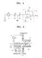
- FIG 1 is a circuit diagram showing the conventional apparatus for driving a MEMS structure and detecting the motion of the driven MEMS structure.
- the apparatus comprises a driving source 5, a first variable capacitor 6a being supplied with a driving signal from the driving source 5 to drive the MEMS structure, a second variable capacitor 6b serially connected to the first variable capacitor 6a, for detecting the motion of the MEMS structure and supplying a motion signal, and an amplifying circuit 8 connected to the second variable capacitor 6b, for outputting an amplified voltage signal V out with respect to an input signal in a current form.
- FIG 2 is a view showing configurations of the first and the second variable capacitors 6a and 6b of FIG 1 .
- the conventional apparatus for driving the MEMS structure and detecting the motion of the driven MEMS structure comprises a first fixed electrode plate 11a supplied with the driving signal, a second fixed electrode plate 11b disposed apart from the first fixed electrode plate 11b by a predetermined distance and opposite to the first fixed electrode plate 11b, and a movable electrode plate 15 integrally formed with the MEMS structure 14, which is supported on a spring 12 and a damper 13 to be movable to a predetermined direction, and located between the first an second fixed electrode plates 11a and 11b.
- the first variable capacitor 6a is embodied by the first fixed electrode plate 11 a and the movable electrode plate 15, and the second variable capacitor 6b is embodied by the movable electrode plate 15 and the second fixed electrode plate 11b.
- US 2002/059829 A1 relates to a dynamic quantity sensor including a semi-conductor substrate, a movable electrode, first fixed electrodes and second fixed electrodes.
- the movable electrode includes a mass portion and electrode portions.
- the mass portion includes two rod portions, which cross each other in an X-shaped configuration.
- the first fixed electrodes form, with the electrode portions, first capacitors for detecting displacement of the movable electrode in a first direction.
- the second fixed electrodes form, with the electrode portions, second capacitors for detecting displacement of the movable electrode in a second direction.
- an aspect of the present invention is to provide an apparatus for driving a MEMS structure and detecting the motion of the driven MEMS structure using a single electrode.
- an apparatus for driving a MEMS structure and detecting motion of the driven MEMS structure using a single electrode comprising: a driving signal generation part for generating and outputting a driving signal to drive the MEMS structure; a motion detection part configured by one single variable capacitor, for detecting the motion of the MEMS structure driven according to the driving signal and outputting a motion current signal corresponding to the motion of the MEMS structure; an amplification part for amplifying the motion current signal output from the motion detection part and outputting a motion voltage signal; a gain adjustment part for amplifying the driving signal input from the driving signal generation part and outputting a driving signal amplified by a predetermined gain; a differential circuit part for performing adding and subtracting operations with respect to the respective signals output from the amplifying and the gain adjustment part and outputting a motion signal without the driving signal by which the driving signal is compensated; and a motion signal detection part for selecting and outputting a motion signal of a predetermined frequency out of the motion signals output from the differential circuit part.
- the variable capacitor is configured by a movable electrode plate integrally formed with the MEMS structure and supplied with the driving signal and a fixed electrode plate disposed opposite to the movable electrode plate and virtually grounded.
- the amplification part may comprise: an amplifier having a negative input terminal connected to the fixed electrode plate, a positive terminal connected to a grounded electrode, and an output terminal; and a first capacitor connected to the amplifier in parallel.
- the variable capacitor may be configured by a movable electrode plate integrally formed with the MEMS structure, and a fixed electrode plate disposed opposite to the movable electrode plate, supplied with the driving signal, and virtually grounded.
- the amplification part may comprise: an amplifier having a negative input terminal connected to the fixed electrode plate, a positive input terminal connected to the driving signal generation part, and an output terminal; and a second capacitor connected to the amplifier in parallel.
- the motion signal detection part may be a band pass filter
- the gain adjustment part may be an amplifier for amplifying the driving signal to the amplitude of the driving signal included in the motion signal output from the amplification part.
- Another aspect of the invention includes a method for achieving the above.
- FIG 3 is a block diagram showing an apparatus for driving a MEMS structure and detecting motion of the driven MEMS structure according to an embodiment of the present invention.
- the apparatus for driving a MEMS structure and detecting motion of the driven MEMS structure comprises a driving signal generation part 20, a motion detection part 21, an amplification part 22, a gain adjustment part 24, a differential circuit part 25, and a motion signal detection part 26.
- the driving signal generation part 20 may be embodied as a voltage source or a current source for outputting a driving signal V s in a periodic square wave or sine wave form to drive the MEMS structure.
- the motion detection part 21 detects motion information of the MEMS structure driven in response to the driving signal V s and supplies a motion signal I.
- the motion signal I obtained by the motion detection part 21 contains the driving signal V s .
- the motion detection part 21 is embodied by a variable capacitor consisting of a movable electrode plate integrally formed with the MEMS structure and a fixed electrode.
- the MEMS structure, which is subjected to the motion detection, such as electrostatic accelerators, actuators, and gyroscopes has to be modeled by the variable capacitor. Accordingly, the detection of change in a capacitance of the variable capacitor enables obtaining the motion information of the MEMS structure.
- the amplification part 22 transforms the motion signal I in a current form supplied from the motion detection part 21 into an amplified motion signal V 1 in a voltage form and outputs the transformed signal.
- the amplification part 22 may be embodied by a charge amplifier constructed by the combination of an amplifier and a capacitor.
- the gain adjustment part 24 is connected to the motion detection part 21 in parallel, for amplifying the driving signal V s output from the driving signal generation part 20 by a predetermined gain.
- the gain adjustment part 24 may be embodied by the combination of an operational amplifier and a resistor or a capacitor connected to the operational amplifier in parallel, or may be embodied by a variable resistor or a multiplier.
- the differential circuit part 25 is supplied with the amplified motion signal V 1 including the driving signal and the driving signal amplified by the gain adjustment part 24, and performs addition and subtraction with respect to the signals.
- the gain adjustment 24 adjusts the gain to make the driving signal included in the amplified motion signal V 1 equal to the driving signal input into the differential circuit part 25 after passing through the gain adjustment part 24, in amplitude.
- the differential circuit part 25 is operated so that the two input driving signals are counterbalanced by each other. Accordingly, a motion signal V 2 output from the differential circuit part 25 excludes the driving signal V s .
- the motion signal V 2 supplied to the motion signal detection part 26 includes a signal corresponding to the change amount ( ⁇ C ) of the capacitance, as well as a DC signal corresponding to a nominal capacitance C 0 and a second high frequency signal, it is necessary to remove these signals.
- the motion signal detection part 26 blocks these unnecessary signals and detects and outputs only the motion signal V out corresponding to the change amount ( ⁇ C ) of the capacitance.
- FIG 4 is a circuit diagram showing a first example of an apparatus for driving a MEMS structure and detecting motion of the driven MEMS structure according to an embodiment of the preset invention.
- a driving signal V s output from a driving source 30 and having a predetermined frequency ⁇ is separated at a node 1 N 1 to be supplied to a variable capacitor 31 and a variable amplifier 34.
- variable capacitor 31 is embodied by a fixed electrode plate 41 and a movable electrode plate 45 integrally formed with a movable MEMS structure 44.
- the driving signal V s of the frequency ⁇ is supplied to the movable electrode plate 45, the MEMS structure 44 supported on a spring 42 and a damper 43 and the movable electrode plate 45 vibrate with the frequency ⁇ in response to the driving signal V s . That is, the motion of the movable electrode plate 45 causes the capacitance C (C 0 + ⁇ C ) of the variable capacitor 31, which consists of the two electrode plates 41 and 45, to be changed. Information about the change in the capacitance C is output as a signal in a current form.
- the variable amplifier 34 amplifies the input driving signal V s by a predetermined gain to make the driving signal V s equal to the driving signal of the frequency ⁇ of the output signals V 1 in an amplitude and outputs the amplified signal to an adder 35.
- the adder 35 performs an operation to counterbalance the two input driving signals of the frequency ⁇ and output a signal V 2 to a band pass filter (BPF) 36.
- BPF band pass filter
- the band pass filter 36 selects and outputs only the motion signal V out of the frequency ⁇ among the input signals V 2 . Using the selected motion signal V out , information about the motion of the variable capacitor 31, i.e., the motion of the MEMS structure can be obtained.
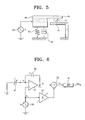
- FIG 6 is a circuit diagram showing a second example of an apparatus for driving a MEMS structure and detecting motion of the driven MEMS structure according to an embodiment of the present invention.
- a driving signal V s output from a driving source 50 and having a predetermined frequency ⁇ is separated at a node 1 P 1 to be supplied to a positive terminal of an amplifier 52 and a variable amplifier 54.
- a variable capacitor 51 having one end connected to a grounded electrode.
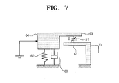
- the configuration of the variable capacitor 51 is described below with reference to FIG 7 .
- the variable capacitor 51 is embodied by a fixed electrode plate 61 to be supplied with the driving signal V s and a movable electrode plate 65 integrally formed with a MEMS structure 64.
- the driving signal V s of the frequency ⁇ is supplied to the fixed electrode plate 61
- the MEMS structure 64 supported on a spring 62 and a damper 63 and the movable electrode plate 65 vibrate with the frequency ⁇ in response to the driving signal V s . That is, the motion of the movable electrode plate 65 causes a capacitance C (C 0 + ⁇ C ) of the variable capacitor 51 consisting of the two electrode plates 61 and 65 to be changed.
- Information about the change in the capacitance C is output as a signal i in a current form.
- an electrical potential at a node 2 P 2 becomes the driving signal V s and the current signal i flowing from the variable capacitor 51 to the node 2 P 2 is output to a capacitor C f 53.
- V 1 denotes an electrical potential at a node 3 P 3 .
- the variable amplifier 54 amplifies the input driving signal Vs by a predetermined gain to the amplitude of the driving signal of frequency ⁇ among the output signals V 1 , and outputs the amplified signal to an adder 55.
- the adder 55 performs an operation so that the two input driving signals of the frequency ⁇ are counterbalanced by each other, and outputs a signal V 2 to a band pass filter (BPF) 56.
- BPF band pass filter
- the band pass filter 56 selects and outputs only the motion signal V out of the frequency ⁇ of the input signals V 2 . Using the selected motion signal V out , information about the motion of the variable capacitor 51, i.e., the motion of the MEMS structure is obtained.
- Another embodiment of the invention includes a method for driving a MEMS (Micro Electro Mechanical System) structure and detecting motion of the driven MEMS structure using a single electrode.
- the method includes generating and outputting a first driving signal to drive the MEMS structure.
- the motion of the MEMS structure driven according to the first driving signal is detected with a variable capacitor and a motion current signal corresponding to the motion of the MEMS structure is outputted.
- the motion current signal is amplified and a motion voltage signal is outputted.
- the first driving signal input is amplified and a second driving signal amplified by a predetermined gain is outputted. Adding and subtracting operations with respect to the motion voltage signal and the second driving signal is performed and a motion signal without the second driving signal is outputted.
- a motion signal of a predetermined frequency is selected and outputted from the motion signal.
- variable capacitor includes a movable electrode plate integral to the MEMS structure and supplied with the first driving signal and a fixed electrode plate disposed opposite to the movable electrode plate and virtually grounded.
- the apparatus for driving the MEMS structure and detecting the motion of the driven MEMS structure is embodied by one single electrode, which reduces overall size of the MEMS structure and also increases voltage efficiency.
Landscapes
- Engineering & Computer Science (AREA)
- Signal Processing (AREA)
- Physics & Mathematics (AREA)
- General Physics & Mathematics (AREA)
- Radar, Positioning & Navigation (AREA)
- Remote Sensing (AREA)
- Computer Hardware Design (AREA)
- Microelectronics & Electronic Packaging (AREA)
- Micromachines (AREA)
Claims (7)
- Vorrichtung zum Antreiben eines MEMS (Micro Electro Mechanical System)-Aufbaus und zum Erfassen einer Bewegung des angetriebenen MEMS-Aufbaus, umfassend:einen Antriebssignal-Erzeugungsteil (20) zum Erzeugen und Ausgeben eines ersten Antriebssignals für das Antreiben des MEMS-Aufbaus,einen Bewegungserfassungsteil (21) zum Erfassen der Bewegung des in Übereinstimmung mit dem ersten Antriebssignal angetriebenen MEMS-Aufbaus und zum Ausgeben eines Bewegungsstromsignals in Entsprechung zu der Bewegung des MEMS-Aufbaus,dadurch gekennzeichnet, dassder Bewegungserfassungsteil (21) eine einzelne variable Kapazität (31) aufweist, die eine bewegliche Elektrodenplatte (45), die mit einem beweglichen MEMS-Aufbau (44) integriert ist, und eine fixierte Elektrodenplatte (41), die der beweglichen Elektrodenplatte (45) gegenüberliegend angeordnet ist, umfasst, wobei das erste Antriebssignal zu der beweglichen Elektrodenplatte (45) zugeführt wird und die fixierte Elektrodenplatte (41) virtuell geerdet ist,einen Verstärkungsteil (22) zum Verstärken des aus dem Bewegungserfassungsteil (21) ausgegebenen Bewegungsstromsignals und zum Ausgeben eines Bewegungsspannungssignals,einen Verstärkungseinstellungsteil (24) zum Verstärken des von dem Antriebssignal-Erzeugungsteil (20) eingegebenen ersten Antriebssignals und zum Ausgeben eines mit einer vorbestimmten Verstärkung verstärkten zweiten Antriebssignals,einen Differentialschaltungsteil (25) zum Durchführen von Additions- und Subtraktionsoperationen in Bezug auf das von dem Verstärkungsteil (22) ausgegebene Bewegungsspannungssignal und das aus dem Verstärkungseinstellungsteil (24) ausgegebene zweite Antriebssignal und zum Ausgeben eines Bewegungssignals ohne das zweite Antriebssignal,undeinen Bewegungssignal-Erfassungsteil (26) zum Auswählen und Ausgeben eines Bewegungssignals mit einer vorbestimmten Frequenz aus dem von dem Differentialschaltungsteil (25) ausgegebenen Bewegungssignal.
- Vorrichtung nach Anspruch 1, wobei der Verstärkungsteil (22) umfasst:einen Verstärker mit einem negativen Eingangsanschluss, der mit der fixierten Elektrodenplatte verbunden ist, einem positiven Anschluss, der mit einer geerdeten Elektrode verbunden ist, und einem Ausgangsanschluss, undeine erste Kapazität, die parallel mit dem Verstärker verbunden ist.
- Vorrichtung nach Anspruch 1, wobei die bewegliche Elektrodenplatte (45) geerdet ist und das erste Antriebssignal zu der fixierten Elektrodenplatte (41) zugeführt wird.
- Vorrichtung nach Anspruch 3, wobei der Verstärkungsteil (22) umfasst:einen Verstärker mit einem negativen Eingangsanschluss, der mit der fixierten Elektrodenplatte verbunden ist, einem positiven Eingangsanschluss, der mit dem Antriebssignal-Erzeugungsteil verbunden ist und einem Ausgangsanschluss, undeine zweite Kapazität, die parallel mit dem Verstärker verbunden ist.
- Vorrichtung nach Anspruch 1, wobei der Bewegungssignal-Erfassungsteil (26) ein Bandpassfilter ist.
- Vorrichtung nach Anspruch 1, wobei der Verstärkungseinstellungsteil (24) ein Verstärker zum Verstärken des ersten Antriebssignals zu einer Amplitude eines in dem von dem Verstärkungsteil ausgegebenen Bewegungssignal enthaltenen dritten Antriebssignals ist.
- Verfahren zum Antreiben eines MEMS (Micro Electro Mechanical System)-Aufbaus und zum Erfassen einer Bewegung des angetriebenen MEMS-Aufbaus, umfassend:Erzeugen und Ausgeben eines ersten Antriebssignals für das Antreiben des MEMS-Aufbaus,Erfassen der Bewegung des in Übereinstimmung mit dem ersten Antriebssignal angetriebenen MEMS-Aufbaus und Ausgeben eines Bewegungsstromsignals in Entsprechung zu der Bewegung des MEMS-Aufbaus,dadurch gekennzeichnet, dassder Schritt zum Erfassen der Bewegung des MEMS-Aufbaus mit einer einzelnen variablen Kapazität (31) durchgeführt wird,wobei das Verfahren weiterhin umfasst:Verstärken des Bewegungsstromsignals und Ausgeben eines Bewegungsspannungssignals,Verstärken des eingegebenen ersten Antriebssignals und Ausgeben eines mit einer vorbestimmten Verstärkung verstärkten zweiten Antriebssignals,Durchführen von Additions- und Subtraktionsoperationen in Bezug auf das Bewegungsspannungssignal und das zweite Antriebssignal und Ausgeben eines Bewegungssignals ohne das zweite Antriebssignal, undAuswählen und Ausgeben eines Bewegungssignals mit einer vorbestimmten Frequenz aus dem Bewegungssignal,wobei der Schritt zum Erfassen der Bewegung des MEMS-Aufbaus mit der variablen Kapazität (31) durchgeführt wird, der eine bewegliche Elektrodenplatte (45), die mit dem MEMS-Aufbau (44) integriert ist und zu der das erste Antriebssignal zugeführt wird, und eine fixierte Elektrodenplatte (41), die der beweglichen Elektrodenplatte (45) gegenüberliegend angeordnet ist und virtuell geerdet ist, umfasst.
Applications Claiming Priority (2)
| Application Number | Priority Date | Filing Date | Title |
|---|---|---|---|
| KR1020030094617A KR100565800B1 (ko) | 2003-12-22 | 2003-12-22 | 단일 전극을 이용한 mems 구조물의 구동 및 구동검지장치 |
| KR2003094617 | 2003-12-22 |
Publications (2)
| Publication Number | Publication Date |
|---|---|
| EP1548403A1 EP1548403A1 (de) | 2005-06-29 |
| EP1548403B1 true EP1548403B1 (de) | 2015-03-04 |
Family
ID=34545887
Family Applications (1)
| Application Number | Title | Priority Date | Filing Date |
|---|---|---|---|
| EP04029996.8A Expired - Lifetime EP1548403B1 (de) | 2003-12-22 | 2004-12-17 | Vorrichtung und Verfahren zum Antrieb einer MEMS-Struktur und zu deren Bewegungsdetektion mittels einer einzigen Elektrode |
Country Status (4)
| Country | Link |
|---|---|
| US (1) | US7178397B2 (de) |
| EP (1) | EP1548403B1 (de) |
| JP (1) | JP4180047B2 (de) |
| KR (1) | KR100565800B1 (de) |
Families Citing this family (14)
| Publication number | Priority date | Publication date | Assignee | Title |
|---|---|---|---|---|
| JP4919819B2 (ja) * | 2007-01-24 | 2012-04-18 | 富士通株式会社 | マイクロマシンデバイスの駆動制御方法および装置 |
| JP4610576B2 (ja) * | 2007-03-30 | 2011-01-12 | 富士通株式会社 | マイクロマシンデバイスの駆動制御方法および装置 |
| US8294539B2 (en) * | 2008-12-18 | 2012-10-23 | Analog Devices, Inc. | Micro-electro-mechanical switch beam construction with minimized beam distortion and method for constructing |
| US8368490B2 (en) | 2008-12-18 | 2013-02-05 | Analog Devices, Inc. | Micro-electro-mechanical switch beam construction with minimized beam distortion and method for constructing |
| US8291765B2 (en) * | 2009-05-04 | 2012-10-23 | Raytheon Company | Carrier modulating accelerometer |
| US8102637B2 (en) * | 2009-07-22 | 2012-01-24 | Analog Devices, Inc. | Control techniques for electrostatic microelectromechanical (MEM) structure |
| US8587328B2 (en) * | 2009-08-25 | 2013-11-19 | Analog Devices, Inc. | Automatic characterization of an actuator based on capacitance measurement |
| JP5538831B2 (ja) * | 2009-11-17 | 2014-07-02 | キヤノン株式会社 | 電気機械変換装置の制御装置と制御方法、及び測定システム |
| JP5722681B2 (ja) * | 2011-03-30 | 2015-05-27 | 株式会社ダイヘン | 模擬負荷装置 |
| CN103105531B (zh) * | 2013-01-18 | 2015-09-30 | 东南大学 | 微电子机械在线式微波频率检测器及其检测方法 |
| JP6197323B2 (ja) * | 2013-03-22 | 2017-09-20 | セイコーエプソン株式会社 | 検出装置、センサー、ジャイロセンサー、電子機器及び移動体 |
| FR3005204A1 (fr) | 2013-04-30 | 2014-10-31 | St Microelectronics Rousset | Dispositif capacitif commutable integre |
| CN104390639B (zh) * | 2014-10-31 | 2017-10-03 | 中国人民解放军国防科学技术大学 | 用于微机械陀螺的刻度因数稳定性提升方法及装置 |
| KR101764338B1 (ko) | 2015-07-14 | 2017-08-03 | 주식회사 인디고엔터테인먼트 | 체어형 트레드밀 모션 트레킹 장치 |
Family Cites Families (10)
| Publication number | Priority date | Publication date | Assignee | Title |
|---|---|---|---|---|
| US5349855A (en) * | 1992-04-07 | 1994-09-27 | The Charles Stark Draper Laboratory, Inc. | Comb drive micromechanical tuning fork gyro |
| US5481914A (en) * | 1994-03-28 | 1996-01-09 | The Charles Stark Draper Laboratory, Inc. | Electronics for coriolis force and other sensors |
| JPH1073437A (ja) * | 1996-08-30 | 1998-03-17 | Fujitsu Ltd | 振動ジャイロの検出回路及びこれを用いた振動ジャイロ装置 |
| US5986497A (en) * | 1997-05-16 | 1999-11-16 | Mitsubishi Denki Kabushiki Kaisha | Interface circuit for capacitive sensor |
| WO1999009418A1 (en) * | 1997-08-13 | 1999-02-25 | California Institute Of Technology | Gyroscopes and compensation |
| US6253612B1 (en) * | 1998-06-05 | 2001-07-03 | Integrated Micro Instruments, Inc. | Generation of mechanical oscillation applicable to vibratory rate gyroscopes |
| US6731121B1 (en) * | 1999-10-15 | 2004-05-04 | Microsensors Corp. | Highly configurable capacitive transducer interface circuit |
| JP3606164B2 (ja) * | 2000-06-02 | 2005-01-05 | 株式会社村田製作所 | 静電容量型外力検出装置 |
| JP2002131331A (ja) * | 2000-10-24 | 2002-05-09 | Denso Corp | 半導体力学量センサ |
| US6393914B1 (en) * | 2001-02-13 | 2002-05-28 | Delphi Technologies, Inc. | Angular accelerometer |
-
2003
- 2003-12-22 KR KR1020030094617A patent/KR100565800B1/ko not_active Expired - Fee Related
-
2004
- 2004-12-17 EP EP04029996.8A patent/EP1548403B1/de not_active Expired - Lifetime
- 2004-12-21 JP JP2004369203A patent/JP4180047B2/ja not_active Expired - Fee Related
- 2004-12-22 US US11/018,830 patent/US7178397B2/en not_active Expired - Fee Related
Also Published As
| Publication number | Publication date |
|---|---|
| EP1548403A1 (de) | 2005-06-29 |
| KR100565800B1 (ko) | 2006-03-29 |
| JP2005177985A (ja) | 2005-07-07 |
| US20050132806A1 (en) | 2005-06-23 |
| JP4180047B2 (ja) | 2008-11-12 |
| KR20050063238A (ko) | 2005-06-28 |
| US7178397B2 (en) | 2007-02-20 |
Similar Documents
| Publication | Publication Date | Title |
|---|---|---|
| EP1548403B1 (de) | Vorrichtung und Verfahren zum Antrieb einer MEMS-Struktur und zu deren Bewegungsdetektion mittels einer einzigen Elektrode | |
| JP3125675B2 (ja) | 容量型センサインターフェース回路 | |
| CN101860778B (zh) | 电容式麦克风的放大电路 | |
| CN102650533B (zh) | 具有活动部分和偏置的传感器 | |
| CN101410694B (zh) | 惯性力传感器 | |
| JP5081852B2 (ja) | 容量式センサおよび角速度センサ | |
| US9513309B2 (en) | Inertia sensor with switching elements | |
| JP2008281555A (ja) | Memsジャイロにおける駆動ノイズ低減のための方法及びシステム | |
| Ali et al. | Noise in piezoelectric MEMS: a review | |
| JP2007256233A5 (de) | ||
| EP3324538A1 (de) | Messschaltung mit einer verstärkerschaltung | |
| CN101256093B (zh) | 用于操作谐振器的可振荡单元的设备 | |
| US8373513B2 (en) | Compensated micro/nano-resonator with improved capacitive detection and method for producing same | |
| JP2006229336A (ja) | 静電容量型マイクロホン | |
| JP4449383B2 (ja) | 発振回路 | |
| Alsaleem et al. | A novel low voltage electrostatic MEMS resonator sensor based on double resonance dynamic amplification | |
| JP2006284272A (ja) | 容量式物理量センサにおけるセンサ回路 | |
| KR101493510B1 (ko) | 외부 회로와 연결되기 위한 단자가 두 개인 멤스 마이크로폰 | |
| EP2184582A1 (de) | Schaltung zur erkennung einer winkelgeschwindigkeit und verfahren zur erkennung einer winkelgeschwindigkeit | |
| CN121002377A (zh) | 传感器驱动装置及用于运行电容式传感器的方法 | |
| JPH02196989A (ja) | 放射線計測用の振動容量型電位計 | |
| EP2002268A1 (de) | Verfahren und vorrichtungen zur differenzsignalisierung unter verwendung von absolutdrucksensoren | |
| JP2004087621A (ja) | 圧電素子制御装置 | |
| JPH09145739A (ja) | 圧電型加速度検出装置 |
Legal Events
| Date | Code | Title | Description |
|---|---|---|---|
| PUAI | Public reference made under article 153(3) epc to a published international application that has entered the european phase |
Free format text: ORIGINAL CODE: 0009012 |
|
| 17P | Request for examination filed |
Effective date: 20041217 |
|
| AK | Designated contracting states |
Kind code of ref document: A1 Designated state(s): AT BE BG CH CY CZ DE DK EE ES FI FR GB GR HU IE IS IT LI LT LU MC NL PL PT RO SE SI SK TR |
|
| AX | Request for extension of the european patent |
Extension state: AL BA HR LV MK YU |
|
| AKX | Designation fees paid |
Designated state(s): DE FR GB |
|
| 17Q | First examination report despatched |
Effective date: 20060630 |
|
| RAP1 | Party data changed (applicant data changed or rights of an application transferred) |
Owner name: SAMSUNG ELECTRONICS CO., LTD. |
|
| REG | Reference to a national code |
Ref country code: DE Ref legal event code: R079 Ref document number: 602004046719 Country of ref document: DE Free format text: PREVIOUS MAIN CLASS: G01C0019560000 Ipc: G01C0019577600 |
|
| RIC1 | Information provided on ipc code assigned before grant |
Ipc: G01C 19/5776 20120101AFI20130919BHEP |
|
| GRAP | Despatch of communication of intention to grant a patent |
Free format text: ORIGINAL CODE: EPIDOSNIGR1 |
|
| INTG | Intention to grant announced |
Effective date: 20140624 |
|
| GRAP | Despatch of communication of intention to grant a patent |
Free format text: ORIGINAL CODE: EPIDOSNIGR1 |
|
| INTG | Intention to grant announced |
Effective date: 20141024 |
|
| GRAS | Grant fee paid |
Free format text: ORIGINAL CODE: EPIDOSNIGR3 |
|
| GRAA | (expected) grant |
Free format text: ORIGINAL CODE: 0009210 |
|
| AK | Designated contracting states |
Kind code of ref document: B1 Designated state(s): DE FR GB |
|
| REG | Reference to a national code |
Ref country code: GB Ref legal event code: FG4D |
|
| REG | Reference to a national code |
Ref country code: DE Ref legal event code: R096 Ref document number: 602004046719 Country of ref document: DE Effective date: 20150416 |
|
| REG | Reference to a national code |
Ref country code: DE Ref legal event code: R097 Ref document number: 602004046719 Country of ref document: DE |
|
| PLBE | No opposition filed within time limit |
Free format text: ORIGINAL CODE: 0009261 |
|
| STAA | Information on the status of an ep patent application or granted ep patent |
Free format text: STATUS: NO OPPOSITION FILED WITHIN TIME LIMIT |
|
| 26N | No opposition filed |
Effective date: 20151207 |
|
| REG | Reference to a national code |
Ref country code: DE Ref legal event code: R119 Ref document number: 602004046719 Country of ref document: DE |
|
| GBPC | Gb: european patent ceased through non-payment of renewal fee |
Effective date: 20151217 |
|
| REG | Reference to a national code |
Ref country code: FR Ref legal event code: ST Effective date: 20160831 |
|
| PG25 | Lapsed in a contracting state [announced via postgrant information from national office to epo] |
Ref country code: GB Free format text: LAPSE BECAUSE OF NON-PAYMENT OF DUE FEES Effective date: 20151217 Ref country code: DE Free format text: LAPSE BECAUSE OF NON-PAYMENT OF DUE FEES Effective date: 20160701 |
|
| PG25 | Lapsed in a contracting state [announced via postgrant information from national office to epo] |
Ref country code: FR Free format text: LAPSE BECAUSE OF NON-PAYMENT OF DUE FEES Effective date: 20151231 |