EP1548348B1 - Dichtungsanordnung, insbesondere für einen Anschluss einer Leitung an einem Expansionsorgan - Google Patents
Dichtungsanordnung, insbesondere für einen Anschluss einer Leitung an einem Expansionsorgan Download PDFInfo
- Publication number
- EP1548348B1 EP1548348B1 EP04028067A EP04028067A EP1548348B1 EP 1548348 B1 EP1548348 B1 EP 1548348B1 EP 04028067 A EP04028067 A EP 04028067A EP 04028067 A EP04028067 A EP 04028067A EP 1548348 B1 EP1548348 B1 EP 1548348B1
- Authority
- EP
- European Patent Office
- Prior art keywords
- line
- sealing
- expansion device
- previous
- ring
- Prior art date
- Legal status (The legal status is an assumption and is not a legal conclusion. Google has not performed a legal analysis and makes no representation as to the accuracy of the status listed.)
- Expired - Lifetime
Links
Images


Classifications
-
- F—MECHANICAL ENGINEERING; LIGHTING; HEATING; WEAPONS; BLASTING
- F16—ENGINEERING ELEMENTS AND UNITS; GENERAL MEASURES FOR PRODUCING AND MAINTAINING EFFECTIVE FUNCTIONING OF MACHINES OR INSTALLATIONS; THERMAL INSULATION IN GENERAL
- F16L—PIPES; JOINTS OR FITTINGS FOR PIPES; SUPPORTS FOR PIPES, CABLES OR PROTECTIVE TUBING; MEANS FOR THERMAL INSULATION IN GENERAL
- F16L41/00—Branching pipes; Joining pipes to walls
- F16L41/08—Joining pipes to walls or pipes, the joined pipe axis being perpendicular to the plane of a wall or to the axis of another pipe
-
- B—PERFORMING OPERATIONS; TRANSPORTING
- B60—VEHICLES IN GENERAL
- B60H—ARRANGEMENTS OF HEATING, COOLING, VENTILATING OR OTHER AIR-TREATING DEVICES SPECIALLY ADAPTED FOR PASSENGER OR GOODS SPACES OF VEHICLES
- B60H1/00—Heating, cooling or ventilating devices
- B60H1/00485—Valves for air-conditioning devices, e.g. thermostatic valves
-
- B—PERFORMING OPERATIONS; TRANSPORTING
- B60—VEHICLES IN GENERAL
- B60H—ARRANGEMENTS OF HEATING, COOLING, VENTILATING OR OTHER AIR-TREATING DEVICES SPECIALLY ADAPTED FOR PASSENGER OR GOODS SPACES OF VEHICLES
- B60H1/00—Heating, cooling or ventilating devices
- B60H1/00507—Details, e.g. mounting arrangements, desaeration devices
- B60H1/00557—Details of ducts or cables
- B60H1/00571—Details of ducts or cables of liquid ducts, e.g. for coolant liquids or refrigerants
-
- F—MECHANICAL ENGINEERING; LIGHTING; HEATING; WEAPONS; BLASTING
- F16—ENGINEERING ELEMENTS AND UNITS; GENERAL MEASURES FOR PRODUCING AND MAINTAINING EFFECTIVE FUNCTIONING OF MACHINES OR INSTALLATIONS; THERMAL INSULATION IN GENERAL
- F16L—PIPES; JOINTS OR FITTINGS FOR PIPES; SUPPORTS FOR PIPES, CABLES OR PROTECTIVE TUBING; MEANS FOR THERMAL INSULATION IN GENERAL
- F16L21/00—Joints with sleeve or socket
- F16L21/02—Joints with sleeve or socket with elastic sealing rings between pipe and sleeve or between pipe and socket, e.g. with rolling or other prefabricated profiled rings
- F16L21/035—Joints with sleeve or socket with elastic sealing rings between pipe and sleeve or between pipe and socket, e.g. with rolling or other prefabricated profiled rings placed around the spigot end before connection
-
- B—PERFORMING OPERATIONS; TRANSPORTING
- B60—VEHICLES IN GENERAL
- B60H—ARRANGEMENTS OF HEATING, COOLING, VENTILATING OR OTHER AIR-TREATING DEVICES SPECIALLY ADAPTED FOR PASSENGER OR GOODS SPACES OF VEHICLES
- B60H1/00—Heating, cooling or ventilating devices
- B60H1/00507—Details, e.g. mounting arrangements, desaeration devices
- B60H2001/00635—Air-tight sealing devices
Definitions
- the invention relates to a sealing arrangement, in particular for a connection of a line to an expansion element of a motor vehicle air conditioning system, according to the preamble of claim 1.
- a 4-way block valve For sealing transitions between four lines and an expansion element, usually a 4-way block valve is provided in conventional automotive air conditioning systems, each having an O-ring seal, wherein the O-ring is disposed in an annular groove which either is formed in the expansion-body housing or on the outer circumference of the conduit. Also, the use of gaskets is known.
- a sealing arrangement which has at least and preferably exactly two sealing elements.
- the sealing elements are provided between a line and a component, wherein the component has an opening into which projects the end of the line.
- At least one of the sealing elements is preferably an O-ring.
- Flat gaskets or profile gaskets are also possible.
- O-rings are available in a variety of dimensions, ie cord diameters and ring diameters, as well as a wide variety of hardnesses, so that standard parts can be used that are inexpensive to purchase. Due to the widespread use of O-rings, sufficient experience is available, so that the number of experiments and thus the development effort can be kept low.
- O-rings made of EPDM or HNBR Preference is given to using O-rings made of EPDM or HNBR, in particular if the refrigerant R134a is to be sealed.
- Flat gaskets have the advantage that they do not slip or only insignificantly slip.
- metallic flat gaskets, or other preferably metallic sealing elements are preferably used.
- At least one sealing element is arranged in a bead or groove provided on the outer circumference of the line or in an annular groove provided on an inner circumferential surface of the component.
- At least one sealing element is preferably in contact with a flange provided on the outer circumference of the line.
- the sealing element can be arranged in an opening provided on the end face of the component annular groove.
- At least one sealing element is arranged on the outer circumference of the line and in abutment against a flange provided on the outer circumference of the line.
- At least two of the sealing elements seal in different directions, that is, for example, in the axial direction (with radial compression of the corresponding sealing element) and in the radial direction (with axial compression of the corresponding sealing element).
- an oblique compression of a sealing element is possible.
- a plurality of sealing elements sealing in the same direction are arranged one behind the other.
- the sealing effect can be improved without unreasonable space requirements.
- the position of the sealing element can be determined by means of an auxiliary element, which is fitted on the line or fitted into the opening, so that the sealing element is arranged in an annular groove.
- transitions between individual stages with different diameters are preferably rounded.
- a guide element in particular of plastic, is arranged for centering the line during assembly in a line end region.
- This is preferably formed by a guide ring, which has an inner circumference corresponding to the outer circumference of the line end region, the outer circumference of the line end region decreasing towards the line end, in particular in the form of a chamfer.
- an inner cross-sectional area of the sealing arrangement is as large as or greater than an inner cross-sectional area of the conduit and / or the component. This means that a medium flowing through the sealing arrangement is not exposed to a bottleneck, so that a flow resistance of the sealing arrangement is reduced or avoided.
- An expansion element in this case an expansion valve 1, an automotive air conditioning system, in which R134a is used as a refrigerant, each has two evaporator-side openings 2a and two user-side openings 2b, in each of which a line 3 is guided.
- two sealing elements 4 according to the first embodiment, two O-rings 5 of EPDM or HNBR per line 3, respectively.
- both on the evaporator side as well as on the user side corresponding sealing arrangements 6 are provided with two substantially pressed in the radial direction O-rings 5 between the lines 3 and the expansion valve 1.
- the O-ring 5 which is arranged closer to the line end, is referred to as the first O-ring 5a and the other O-ring 5 as the second O-ring 5b.
- the lines 2 have a flange 7 and a bead 8 for positioning the O-rings 5 at their expansion valve end.
- the openings 2a and 2b each have in the region in which the corresponding line 3 projects and slightly beyond, a substantially cylindrical cross-section, which widens outwardly in two stages, the transitions between the steps rounded or at least bevelled are not to damage the O-rings 5 during assembly.
- the first O-ring 5a is positioned in the bead 8 and is pressed against the substantially cylindrical part of the corresponding opening 2a and 2b, respectively.
- the second O-ring 5b which has a larger diameter than the first O-ring 5a abuts against the end surface of the flange 7 and the outer periphery of the conduit 3 and is pressed against the rounded end portion of the first stage.
- the flange 7 is according to the first embodiment at the transition between the first and the second stage, the second stage is only the whole or partial reception of the flange 7 is used.
- the static internal pressure for example, about 6bar, in the space between the first O. Ring 5a and the second O-ring 5b, the atmospheric pressure and outside the second O-ring 5b also the atmospheric pressure.
- first embodiment is the user side, in Fig. 3
- the line 3 is machined so that it has several stages with decreasing towards the outside outside diameter.
- a first O-ring 5a is arranged, which is positioned by means of an auxiliary element 11.
- the auxiliary member 11 is cylindrical, wherein between the stage with the smallest outer diameter and the auxiliary member 11 small, in the Fig. 3 not shown undercuts are provided so that the auxiliary member 11 frictionally and positively sits on the line 3.
- the auxiliary element for example, also shrunk or attached by gluing on the line 3.
- the first O-ring 5a is here in Radial direction pressed against the substantially cylindrical portion of the opening 2b.
- the second O-ring 5 b which has a significantly larger diameter than the first O-ring 5 a compared to the first embodiment, is arranged frontally in an annular groove 12 formed in the expansion valve 1 and closed by a flange 7 of the line 3 becomes. He is pressed in the axial direction against the expansion valve 1.
- a flat gasket 5b ' is used, wherein the flange 7 of the line 3, the flat gasket 5b' presses into an annular recess in the expansion valve 1.
- the arrangement of the first O-ring 5a corresponds to that of the first embodiment.
- two O-rings 5a and 5b are again provided as sealing elements, wherein the arrangement of the first O-ring 5a corresponds to that of the first embodiment.
- the second O-ring 5b which has an inner diameter which is slightly larger than the diameter of the opening 2a and 2b, is arranged in an annular recess in the expansion valve 1, wherein it from a flange 7 of the conduit 3 against the same opposite surface the recess is pressed.
- the second O-ring 5b is in this case only on the end-side end face of the flange 7 and not on the outer circumferential surface of the line 3 at.
- Fig. 6 shows the second embodiment according to which the two O-rings 5a and 5b are arranged approximately coaxially to each other, for which the outer, second O-ring 5b an annular groove is provided on the end face of the expansion valve 1 and by a flange 7 of the line. 3 in the direction of the groove bottom is pressed.
- the inner, first O-ring 5a is located at the transition between flange 7 and outer circumferential surface of the line 3 and a rounded transition from a first to a second stage (see ring 5b of the embodiment of Fig. 1 ).
- Fig. 7 The embodiment that is in Fig. 7 is shown, provides an arrangement of two identical O-rings 5a and 5b in succession in two corresponding beads 8 (evaporator side) or annular grooves (user side) before.
- the arrangement of the second O-ring 5b corresponds to that of the first embodiment.
- the first O-ring 5a is arranged in an annular groove 13 provided on the inner lateral surface of the opening 2a or 2b, and the end of the conduit 3 has no bead 8, but runs without substantial changes in diameter until the rounded end.
- the O-ring 5a is compressed by the groove bottom of the annular groove 13 and the outer circumferential surface of the conduit 3, so that leakage can be prevented.
- CO 2 (R 744) is used as the refrigerant.
- a flat gasket 5b ' is used instead of the second O-ring 5b, wherein the flange 7 of the conduit 3 forms the flat gasket 5b' in an annular recess in the expansion organ 1 presses.
- the arrangement of the first O-ring 5a corresponds to that of the first embodiment.
- the sealing elements in this case are metallic seals.
- two metallic flat gaskets are used for sealing.
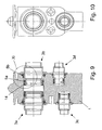
- FIGS. 9 to 11 show an expansion valve 1 with four connected refrigerant lines 3, namely an engine-side suction line 3a, an evaporator-side suction line 3b, a motor-space-side pressure line 3c and an evaporator-side pressure line 3d.
- a guide element in this case a guide ring 14 made of plastic, provided at the line end region, which ensures the centering.
- the guide ring 14 protects during assembly, the two sealing surfaces of the expansion valve 1 from mechanical damage.
- the radial O-ring 5a is secured against slipping by the radial O-ring 5a by the guide ring 14 and the diagonal O-ring 5b, but the inner diameter of the rear O-ring 5b is larger than the inner diameter of the wire-end O-ring 5a smaller than the outer diameter thereof.
- the line 3 is reshaped in its end region such that the inner diameter corresponds at least to that of the further course of the line 3, so that the hydraulically effective diameter in the region of the connection is not reduced.
- the preparation is carried out as follows: Starting from the line internal diameter Di, the line is first expanded to a larger inner diameter D1, then a flange 7 is formed with an outer diameter D2. To accommodate the radial O-ring 5a, the line end is brought to the line inner diameter D3, which is greater than or equal to the line internal diameter Di, and slightly widened at the end of the line, with a kind of chamfer for receiving the guide ring 14 is formed on the outer circumference of the line end.
- the inner diameter profile of the expansion valve 1 is as follows, the description being from the inside to the outside: after a region 15 of constant diameter, connected via a transition radius 16, a conical region 17 with outwardly enlarging diameter, wherein the angle between the conical portion 17th and the line longitudinal axis is 5 ° to 30 °. This is followed by a transition region, a second conical region 18, wherein the angle between the second conical region 18 and the line longitudinal axis is 2 ° to 20 °, and an outwardly widening in a radius region 19, the tangential to the second conical region 18th followed.
- the radius of the outwardly widening portion 19 is 2% to 30% of the tube outer diameter.
- the radius of the outwardly widening region 19 merges into a contact surface 20 for the flange 7.
- the fixation of the line 3 in the expansion valve 1 can be done by means of a holding plate, not shown, which is connected for example via screws to the expansion valve 1.
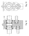
- FIGS. 12 to 14 is a variant of the embodiment of Fig. 9 shown, which apart from the diameters of the line 3 on Reason another forming consistent with the embodiment described above.
- the line 3 is reshaped in its end region such that the inside diameter likewise corresponds at least to that of the further course of the line 3, so that even in this variant the hydraulically effective diameter in the region of the connection is not reduced.
- the preparation is carried out as follows: Starting from the line internal diameter Di, the line is first expanded to an outer diameter D2, then a flange 7 is formed with a corresponding outer diameter D2. The line 3 goes after the flange 7 in a line inside diameter D4.
- the line end is brought to the line inner diameter D3, which is greater than or equal to the line internal diameter Di but smaller than the line inner diameter D4, and slightly widened at the end of the line, again a kind of chamfer for receiving the guide ring 14 is formed ,
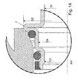
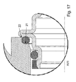
- FIGS. 15 to 17 corresponds to the shape of the line 3 and their preparation of the embodiment of Fig. 9 , Wherein an embodiment according to the variant of the embodiment of Fig. 9 is possible.
- Fig. 9 In contrast to the embodiment of Fig. 9 is the outside arranged O-ring 5b not a diagonal sealing element, but an axial sealing element, ie it is pressed in the direction of the longitudinal axis of the pipe by means of the flange 7 against its substantially extending in the radial direction with respect to the longitudinal axis of the contact surface.
- the inner diameter profile of the expansion valve 1 is the following, wherein the description is from the inside to the outside: after a region 15 with constant diameter, connected via a transition radius 16, a conical portion 17 with outwardly enlarging diameter, wherein the angle between the conical portion 17 and the longitudinal axis of the pipe is 5 ° to 30 °.
- a transition area This is followed by a region 21 extending in the radial direction to the line longitudinal axis, a region extending coaxially to the line longitudinal axis and a region 22 extending in the radial direction to the line longitudinal axis which serves as a bearing for the flange 7 and limits squeezing of the O-ring 5b , each separated by rounded transitions.
Landscapes
- Engineering & Computer Science (AREA)
- General Engineering & Computer Science (AREA)
- Mechanical Engineering (AREA)
- Physics & Mathematics (AREA)
- Thermal Sciences (AREA)
- Gasket Seals (AREA)
- Electroluminescent Light Sources (AREA)
- Structures Or Materials For Encapsulating Or Coating Semiconductor Devices Or Solid State Devices (AREA)
Description
- Die Erfindung betrifft eine Dichtungsanordnung, insbesondere für einen Anschluss einer Leitung an einem Expansionsorgan einer Kraftfahrzeug-Klimaanlage, gemäß dem Oberbegriff des Anspruchs 1.
- Zur Abdichtung von Übergängen zwischen vier Leitungen und einem Expansionsorgan, in der Regel ein 4-Wege-Blockventil, ist bei herkömmlichen Kraftfahrzeug-Klimaanlagen eine jeweils eine O-Ring-Dichtung vorgesehen, wobei der O-Ring in einer Ringnut angeordnet ist, welche entweder im Expansionsorgan-Gehäuse oder am Außenumfang der Leitung ausgebildet ist. Ebenfalls ist die Verwendung von Flachdichtungen bekannt.
- Derartige Dichtungsanordnungen sind z.B. aus
EP-A-0 916 886 oderUS-A-3 929 356 bekannt. - An den verdampferseitigen Leitungen sind üblicherweise Rohrsicken mit entsprechend am Expansionsorgan verschraubten Halteplatten verwendet, während auf der anderen Seite (Nutzerseite) häufig Einzel- oder Doppelflansche verwendet werden. Hierbei treten bei Beschädigung des Dichtelements oder bei Verschmutzungen durch Fremdelemente, wie Späne, oder Verunreinigungen oder bei falscher Montage des Dichtelements Leckagen auf, so dass die Umwelt durch das Kältemittel, in der Regel R134a, belastet wird, die Kälteleistung sinkt und die Nutzungsdauer verkürzt wird.
- Eine derartige Dichtungsanordnung lässt daher noch Wünsche, insbesondere in Hinblick auf die Dichtheit, offen.
- Es ist Aufgabe der Erfindung, eine verbesserte Dichtungsanordnung zur Verfügung zu stellen.
- Diese Aufgabe wird gelöst durch eine Dichtungsanordnung mit den Merkmalen des Anspruchs 1. Vorteilhafte Ausgestaltungen sind Gegenstand der Unteransprüche.
- Erfindungsgemäß ist eine Dichtungsanordnung vorgesehen, die mindestens und vorzugsweise genau zwei Dichtelemente aufweist. Dabei sind die Dichtelemente zwischen einer Leitung und einem Bauteil vorgesehen, wobei das Bauteil eine Öffnung aufweist, in die das Ende der Leitung hineinragt. Bevorzugt handelt es sich bei mindestens einem der Dichtelemente um einen O-Ring. Flachdichtungen oder Profildichtungen kommen ebenfalls in Frage. O-Ringe gibt es in den unterschiedlichsten Abmessungen, das heißt Schnurdurchmessern und Ringdurchmessern, sowie den unterschiedlichsten Härten, so dass Standardteile verwendet werden können, die preisgünstig zu erwerben sind. Auf Grund der weiten Verbreitung von O-Ringen sind ausreichende Erfahrungswerte vorhanden, so dass die Anzahl von Versuchen und damit der Entwicklungsaufwand gering gehalten werden kann. Bevorzugt werden O-Ringe aus EPDM oder HNBR verwendet, insbesondere wenn das Kältemittel R134a abgedichtet werden soll. Flachdichtungen haben den Vorteil, dass sie nicht oder nur unwesentlich verrutschen. Insbesondere bei der Verwendung von CO2 als Kältemittel werden bevorzugt Flachdichtungen, insbesondere metallische Flachdichtungen, oder andere bevorzugt metallische Dichtelemente verwendet.
- Vorzugsweise ist mindestens ein Dichtelement in einer am Außenumfang der Leitung vorgesehen Sicke oder Nut oder in einer an einer Innenmantelfläche des Bauteils vorgesehenen Ringnut angeordnet.
- Alternativ oder in Kombination hiermit ist bevorzugt mindestens ein Dichtelement in Anlage an einem am Außenumfang der Leitung vorgesehen Flansch. Dabei kann das Dichtelement in einer an der Stirnfläche des Bauteils vorgesehenen Ringnut angeordnet sein.
- Um einen schrägen Kraftverlauf zu erzeugen ist mindestens ein Dichtelement am Außenumfang der Leitung angeordnet und in Anlage an einem am Außenumfang der Leitung vorgesehen Flansch.
- Bevorzugt dichten mindestens zwei der Dichtelemente in unterschiedlichen Richtungen ab, also beispielsweise in axialer Richtung (bei radialer Zusammenpressung des entsprechenden Dichtelements) und in radialer Richtung (bei axialer Zusammenpressung des entsprechenden Dichtelements). Ebenfalls ist ein schräges Zusammenpressen eines Dichtelements möglich.
- Gemäß einer vorteilhaften Ausführungsform sind mehrere in die gleiche Richtung abdichtende Dichtelemente hintereinander angeordnet. Somit kann die Dichtwirkung unter Umständen ohne unzumutbaren Platzbedarf verbessert werden.
- Die Positionsbestimmung des Dichtelements kann mittels eines Hilfselements erfolgen, das auf die Leitung aufgepasst oder in die Öffnung eingepasst wird, so dass das Dichtelement in einer Ringnut angeordnet ist.
- Zur Vermeidung von Beschädigungen der Dichtelemente bei der Montage sind bevorzugt die Übergänge zwischen einzelnen Stufen mit unterschiedlichen Durchmessern abgerundet.
- Vorzugsweise ist zur Zentrierung der Leitung bei der Montage in einem Leitungsendbereich ein Führungselement, insbesondere aus Kunststoff, angeordnet. Dieses wird bevorzugt durch einen Führungsring gebildet, welcher eine dem Außenumfang des Leitungsendbereichs entsprechende Innenkontur aufweist, wobei sich der Außenumfang des Leitungsendbereichs zum Leitungsende hin verkleinert, insbesondere in Form einer Fase.
- Gemäß einem vorteilhaften Ausführungsbeispiel ist eine innere Querschnittsfläche der Dichtungsanordnung so groß wie oder größer als eine innere Querschnittsfläche der Leitung und/oder des Bauteils. Dies bedeutet, dass ein die Dichtungsanordnung durchströmendes Medium keiner Engstelle ausgesetzt ist, so dass ein Strömungswiderstand der Dichtungsanordnung verringert oder vermieden wird.
- Im Folgenden wird die Erfindung anhand von mehreren Ausführungsbeispielen, teilweise mit Varianten, unter Bezugnahme auf die Zeichnung im Einzelnen erläutert. In der Zeichnung zeigen:
- Fig. 1
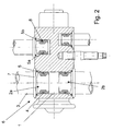
- eine perspektivische Ansicht einer Dichtungsanordnung in teilweiser Explosionsdarstellung gemäß dem Stand der Technik,
- Fig. 2
- einen Schnitt durch die Dichtungsanordnung von
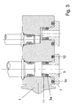
Fig. 1 , - Fig. 3
- einen Schnitt durch eine Dichtungsanordnung gemäß dem ersten Ausführungsbeispiel,
- Fig. 4
- einen Schnitt durch eine Dichtungsanordnung gemäß dem Stand der Technik,
- Fig. 5
- einen Schnitt durch eine Dichtungsanordnung gemäß dem Stand der Technik,
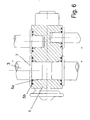
- Fig. 6
- einen Schnitt durch eine Dichtungsanordnung gemäß dem zweiten Ausführungsbeispiel,
- Fig. 7
- einen Schnitt durch eine Dichtungsanordnung gemäß dem Stand der Technik,
- Fig. 8
- einen Schnitt durch eine Dichtungsanordnung gemäß dem Stand der Technik,
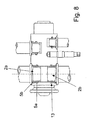
- Fig. 9
- einen Schnitt durch ein Expansionsventil mit vier Leitungen mit Dichtungsanordnungen gemäß dem Stand der Technik,
- Fig. 10
- eine Seitenansicht des Expansionsventils von
Fig. 9 ohne Darstellung der Leitungen, - Fig. 11
- einen Schnitt durch eine der Dichtungsanordnungen von
Fig. 9 , wobei die Dichtelemente unverformt dargestellt sind, - Fig. 12
- einen Schnitt durch ein Expansionsventil mit vier Leitungen mit Dichtungsanordnungen gemäß der Variante des Ausführungsbeispiels von
Fig. 9 . - Fig. 13
- eine Seitenansicht des Expansionsventils von
Fig. 12 ohne Darstellung der Leitungen, - Fig. 14
- einen Schnitt durch eine der Dichtungsanordnungen von
Fig. 12 , wobei die Dichtelemente unverformt dargestellt sind, - Fig. 15
- einen Schnitt durch ein Expansionsventil mit vier Leitungen mit Dichtungsanordnungen gemäß dem Stand der Technik,
- Fig. 16
- eine Seitenansicht des Expansionsventils von
Fig. 15 ohne Darstellung der Leitungen, und - Fig. 17
- einen Schnitt durch eine der Dichtungsanordnungen von
Fig. 15 , wobei die Dichtelemente unverformt dargestellt sind. - Ein Expansionsorgan, vorliegend ein Expansionsventil 1, einer Kraftfahrzeug-Klimaanlage, bei welcher R134a als Kältemittel verwendet wird, weist je zwei verdampferseitige Öffnungen 2a und zwei nutzerseitige Öffnungen 2b auf, in die je eine Leitung 3 geführt ist. Zur Abdichtung zwischen einzelnen Leitungen 3 und dem Expansionsventil 1, vorliegend einem 4-Wege-Blockventil, sind jeweils zwei Dichtelemente 4, gemäß dem ersten Ausführungsbeispiel zwei O-Ringe 5 aus EPDM oder HNBR je Leitung 3, vorgesehen. Hierbei sind sowohl verdampferseitig als auch nutzerseitig jeweils einander entsprechende Dichtungsanordnungen 6 mit zwei im Wesentlichen in radialer Richtung angepressten O-Ringen 5 zwischen den Leitungen 3 und dem Expansionsventil 1 vorgesehen. Dabei wird im Folgenden der O-Ring 5, der näher am Leitungsende angeordnet ist, als erster O-Ring 5a und der andere O-Ring 5 als zweiter O-Ring 5b bezeichnet.
- Die Leitungen 2 weisen zur Positionierung der O-Ringe 5 an ihrem expansionsventilseitigen Ende einen Flansch 7 und eine Sicke 8 auf. Die Öffnungen 2a und 2b weisen jeweils im Bereich, in den die entsprechende Leitung 3 ragt und etwas darüber hinaus, einen im Wesentlichen zylinderförmigen Querschnitt auf, der sich nach außen hin in zwei Stufen erweitert, wobei die Übergänge zwischen den Stufen abgerundet oder zumindest abgeschrägt sind, um bei der Montage die O-Ringe 5 nicht zu beschädigen. Der erste O-Ring 5a ist in der Sicke 8 positioniert und wird gegen den im Wesentlichen zylinderförmigen Teil der entsprechenden Öffnung 2a bzw. 2b gepresst. Der zweite O-Ring 5b, welcher einen größeren Durchmesser als der erste O-Ring 5a aufweist, liegt an der endseitigen Fläche des Flansches 7 und dem Außenumfang der Leitung 3 an und wird gegen den abgerundeten Endbereich der ersten Stufe gepresst. Der Flansch 7 liegt gemäß dem ersten Ausführungsbeispiel am Übergang zwischen der ersten und der zweiten Stufe an, wobei die zweite Stufe lediglich der ganzen oder teilweisen Aufnahme des Flansches 7 dient.
- Hierbei herrscht im Idealfall, das heißt sofern keiner der beiden O-Ringe 5 je Dichtungsanordnung 6 beschädigt ist und keine anderen Leckagegründe vorliegen, im Bereich vor dem ersten O-Ring 5a der statische Innendruck, beispielsweise ca. 6bar, im Zwischenraum zwischen dem ersten O-Ring 5a und dem zweiten O-Ring 5b der atmosphärische Druck und außerhalb des zweiten O-Ringes 5b ebenfalls der atmosphärische Druck.
- Gemäß dem in
Fig. 3 dargestellten ersten Ausführungsbeispiel ist nutzerseitig, inFig. 3 wie auch den folgenden Figuren unten dargestellt, die Leitung 3 spanabhebend derart bearbeitet, dass sie mehrere Stufen mit zum Ende hin abnehmenden Außendurchmesser aufweist. Hierbei ist endseitig, das heißt auf der Stufe mit dem kleinsten Außendurchmesser, ein erster O-Ring 5a angeordnet, welcher mittels eines Hilfselements 11 positioniert ist. Das Hilfselement 11 ist zylinderförmig ausgebildet, wobei zwischen der Stufe mit dem kleinsten Außendurchmesser und dem Hilfselement 11 kleine, in derFig. 3 nicht dargestellte Hinterschneidungen vorgesehen sind, so dass das Hilfselement 11 reib- und formschlüssig auf der Leitung 3 sitzt. Alternativ kann das Hilfselement beispielsweise auch aufgeschrumpft oder mittels Kleben an der Leitung 3 befestigt werden. Der erste O-Ring 5a wird hierbei in radialer Richtung gegen den im Wesentlichen zylinderförmigen Teil der Öffnung 2b gepresst. - Der zweite O-Ring 5b, welcher verglichen mit dem ersten Ausführungsbeispiel, einen deutlich größeren Durchmesser als der erste O-Ring 5a aufweist, ist stirnseitig in einer Ringnut 12 angeordnet, die im Expansionsventil 1 ausgebildet und die von einem Flansch 7 der Leitung 3 verschlossen wird. Dabei wird er in axialer Richtung gegen das Expansionsventil 1 gepresst.
- Beim in
Fig. 4 dargestellten Ausführungsbeispiel wird sowohl verdampferseitig als auch nutzerseitig an Stelle des zweiten O-Rings 5b eine Flachdichtung 5b' verwendet, wobei der Flansch 7 der Leitung 3 die Flachdichtung 5b' in eine ringförmige Ausnehmung im Expansionsventil 1 presst. Die Anordnung des ersten O-Rings 5a entspricht der des ersten Ausführungsbeispiels. - Gemäß dem in
Fig. 5 dargestellten Ausführungsbeispiel sind wiederum zwei O-Ringe 5a und 5b als Dichtelemente vorgesehen, wobei die Anordnung des erstem O-Rings 5a der des ersten Ausführungsbeispiels entspricht. Der zweite O-Ring 5b, welcher einen Innendurchmesser aufweist, der etwas größer als der Durchmesser der Öffnung 2a bzw. 2b ist, ist in einer ringförmigen Ausnehmung im Expansionsventil 1 angeordnet, wobei er von einem Flansch 7 der Leitung 3 gegen die demselben gegenüberliegende Fläche der Ausnehmung gepresst wird. Der zweite O-Ring 5b liegt hierbei nur an der endseitigen Stirnfläche des Flansches 7 und nicht an der Außenmantelfläche der Leitung 3 an. -
Fig. 6 zeigt das zweite Ausführungsbeispiel gemäß dem die beiden O-Ringe 5a und 5b etwa koaxial zueinander angeordnet sind, wofür für den äußeren, zweiten O-Ring 5b eine ringförmige Nut an der Stirnfläche des Expansionsventils 1 vorgesehen ist und er durch einen Flansch 7 der Leitung 3 in Richtung des Nutgrunds gepresst wird. Der innere, erste O-Ring 5a liegt am Übergang zwischen Flansch 7 und Außenmantelfläche der Leitung 3 sowie einem abgerundeten Übergang von einer ersten zu einer zweiten Stufe an (vgl. Ring 5b des Ausführungsbeispiels vonFig. 1 ). - Das Ausführungsbeispiel, das in
Fig. 7 dargestellt ist, sieht eine Anordnung zweier gleicher O-Ringe 5a und 5b hintereinander in zwei einander entsprechenden Sicken 8 (verdampferseitig) bzw. Ringnuten (nutzerseitig) vor. - Gemäß dem in
Fig. 8 dargestellten Ausführungsbeispiel entspricht die Anordnung des zweiten O-Rings 5b der des ersten Ausführungsbeispiels. Der erste O-Ring 5a ist in einer an der Innenmantelfläche der Öffnung 2a bzw. 2b vorgesehenen Ringnut 13 angeordnet und das Ende der Leitung 3 weist keine Sicke 8 auf, sondern verläuft ohne wesentliche Durchmesseränderungen bis zum abgerundeten Ende. Hierbei wird der O-Ring 5a von dem Nutgrund der Ringnut 13 und der Außenmantelfläche der Leitung 3 zusammengepresst, so dass eine Leckage verhindert werden kann. - Gemäß dem Ausführungsbeispiel, für das auf
Fig. 4 Bezug genommen wird, wird im Gegensatz zu den zuvor beschriebenen Ausführungsbeispielen CO2 (R744) als Kältemittel verwendet. Zur sicheren Abdichtung der einzelnen Leitungen 3 wird sowohl verdampferseitig als auch nutzerseitig, wie beim dritten Ausführungsbeispiel beschrieben, an Stelle des zweiten O-Rings 5b je eine Flachdichtung 5b' verwendet, wobei der Flansch 7 der Leitung 3 die Flachdichtung 5b' in eine ringförmige Ausnehmung im Expansionsorgan 1 presst. Die Anordnung des ersten O-Rings 5a entspricht der des ersten Ausführungsbeispiels. Bei den Dichtelementen handelt es sich in diesem Fall um metallische Dichtungen. - Gemäß einer nicht in der Zeichnung dargestellten Variante dieses Ausführungsbeispiels werden zwei metallische Flachdichtungen zur Abdichtung verwendet.
-
Figuren 9 bis 11 zeigen ein Expansionsventil 1 mit vier angeschlossenen Kältemittel-Leitungen 3, nämlich einer motorraumseitigen Saugleitung 3a, einer verdampferseitigen Saugleitung 3b, einer motorraumseitigen Druckleitung 3c und einer verdampferseitigen Druckleitung 3d. - Die Dichtwirkung wird gemäß dem neunten Ausführungsbeispiel jeweils mittels einer Dichtungsanordnung mit zwei Dichtelementen 4, vorliegend zwei O-Ringen 5, nämlich einem diagonalen, d.h. schräg zur Längsachse der Leitung belasteten, beabstandet vom Ende der Leitung 3 angeordneten O-Ring 5b und einem radialen, d.h. in radialer Richtung zur Längsachse der Leitung 3 belasteten, näher am Leitungsende angeordneten O-Ring 5a bewirkt.
- Ferner ist ein Führungselement, vorliegend ein Führungsring 14 aus Kunststoff, am Leitungsendbereich vorgesehen, welches die Zentrierung sicherstellt. Der Führungsring 14 schützt während der Montage die beiden Dichtflächen des Expansionsventils 1 vor einer mechanischen Beschädigung.
- Auf Grund des sich ändernden Durchmessers der Leitung 3, siehe insbesondere
Fig. 11 , wird der radiale O-Ring 5a durch den Führungsring 14 und der diagonale O-Ring 5b durch den radialen O-Ring 5a gegen Abrutschen gesichert, wobei der Innendurchmesser des hinteren O-Rings 5b größer als der Innendurchmesser des leitungsendseitigen O-Rings 5a aber kleiner als der Außendurchmesser desselben ist. - Die Leitung 3 wird in ihrem Endbereich derart umgeformt, dass der Innendurchmesser mindestens dem des weiteren Verlaufs der Leitung 3 entspricht, so dass der hydraulisch wirksame Durchmesser im Bereich der Verbindung nicht verkleinert wird. Die Herstellung erfolgt folgendermaßen: Ausgehend vom Leitungsinnendurchmesser Di wird die Leitung zunächst auf einen größeren Leitungsinnendurchmesser D1 aufgeweitet, anschließend wird ein Flansch 7 mit einem Außendurchmesser D2 geformt. Zur Aufnahme des radialen O-Rings 5a wird das Leitungsende auf den Leitungsinnendurchmesser D3, der größer oder gleich dem Leitungsinnendurchmesser Di ist, gebracht und am Leitungsende etwas aufgeweitet, wobei auch eine Art Fase zur Aufnahme des Führungsrings 14 am Außenumfang des Leitungsendes angeformt wird.
- Der Innendurchmesserverlauf des Expansionsventils 1 ist Folgender, wobei die Beschreibung von innen nach außen erfolgt: nach einem Bereich 15 mit konstantem Durchmesser folgt, verbunden über einen Übergangsradius 16 ein konischer Bereich 17 mit sich nach außen vergrößerndem Durchmesser, wobei der Winkel zwischen dem konischen Bereich 17 und der Leitungslängsachse 5° bis 30° beträgt. Anschließend folgt ein Übergangsbereich, ein zweiter konischer Bereich 18, wobei der Winkel zwischen dem zweiten konischen Bereich 18 und der Leitungslängsachse 2° bis 20° beträgt, und ein in einem Radius sich nach außen erweiternden Bereich 19, der tangential an den zweiten konischen Bereich 18 anschließt. Der Radius des sich nach außen erweiternden Bereichs 19 beträgt 2% bis 30% des Rohraußendurchmessers. Der Radius des nach außen erweiternden Bereichs 19 geht in eine Anlagefläche 20 für den Flansch 7 über.
- Die Fixierung der Leitung 3 im Expansionsventil 1 kann mittels einer nicht dargestellten Halteplatte erfolgen, welche beispielsweise über Schrauben mit dem Expansionsventil 1 verbunden ist.
- In den
Figuren 12 bis 14 ist eine Variante des Ausführungsbeispiels vonFig. 9 dargestellt, welche abgesehen von den Durchmessern der Leitung 3 auf Grund einer anderen Umformung mit dem zuvor beschriebenen Ausführungsbeispiel übereinstimmt. - Die Leitung 3 wird gemäß der Variante in ihrem Endbereich derart umgeformt, dass der Innendurchmesser ebenfalls mindestens dem des weiteren Verlaufs der Leitung 3 entspricht, so dass auch bei dieser Variante der hydraulisch wirksame Durchmesser im Bereich der Verbindung nicht verkleinert wird. Die Herstellung erfolgt folgendermaßen: Ausgehend vom Leitungsinnendurchmesser Di wird die Leitung zunächst auf einen Außendurchmesser D2 aufgeweitet, anschließend wird ein Flansch 7 mit entsprechendem Außendurchmesser D2 geformt. Die Leitung 3 geht nach dem Flansch 7 in einen Leitungsinnendurchmesser D4 über. Zur Aufnahme des radialen O-Rings 5a wird das Leitungsende auf den Leitungsinnendurchmesser D3, der größer oder gleich dem Leitungsinnendurchmesser Di aber kleiner als der Leitungsinnendurchmesser D4 ist, gebracht und am Leitungsende etwas aufgeweitet, wobei wiederum eine Art Fase zur Aufnahme des Führungsrings 14 angeformt wird.
- Gemäß dem Ausführungsbeispiel, das in den
Figuren 15 bis 17 dargestellt ist, entspricht die Form der Leitung 3 und deren Herstellung der des Ausführungsbeispiels vonFig. 9 , wobei auch eine Ausgestaltung gemäß der Variante des Ausführungsbeispiels vonFig. 9 möglich ist. - In Unterschied zum Ausführungsbeispiel von
Fig. 9 ist der außenseitig angeordnete O-Ring 5b nicht kein diagonales Dichtelement, sondern ein axiales Dichtelement, d.h. es wird in Richtung der Leitungslängsachse mit Hilfe des Flansches 7 gegen seine im Wesentlichen in radialer Richtung bezüglich der Leitungslängsachse verlaufende Anlagefläche gepresst. - Der Innendurchmesserverlauf des Expansionsventils 1 ist Folgender, wobei die Beschreibung von innen nach außen erfolgt: nach einem Bereich 15 mit konstantem Durchmesser folgt, verbunden über einen Übergangsradius 16 ein konischer Bereich 17 mit sich nach außen vergrößerndem Durchmesser, wobei der Winkel zwischen dem konischen Bereich 17 und der Leitungslängsachse 5° bis 30° beträgt. Anschließend folgt ein Übergangsbereich. Es folgt ein in radialer Richtung zur Leitungslängsachse verlaufender Bereich 21, ein senkrecht, d.h. koaxial zur Leitungslängsachse verlaufender Bereich und ein wiederum in radialer Richtung zur Leitungslängsachse verlaufender Bereich 22, welcher als Anlage für den Flansch 7 dient und das Quetschen des O-Rings 5b begrenzt, jeweils getrennt voneinander durch abgerundete Übergänge.
-
- 1
- Expansionsventil, Expansionsorgan
- 2a, 2b
- Öffnung
- 3
- Leitung
- 4
- Dichtelement
- 5, 5a, 5b
- O-Ring
- 5b'
- Flachdichtung
- 6
- Dichtungsanordnung
- 7
- Flansch
- 8
- Sicke
- 11
- Hilfselement
- 12
- Ringnut
- 13
- Ringnut
- 14
- Führungsring
- 15
- Bereich
- 16
- Übergangsradius
- 17
- konischer Bereich
- 18
- zweiter konischer Bereich
- 19
- Bereich
- 20
- Anlagefläche
- 21
- Bereich
- 22
- Bereich
- Di
- Leitungsinnendurchmesser
- D1
- Leitungsinnendurchmesser
- D2
- Außendurchmesser
- D3
- Leitungsinnendurchmesser
- D4
- Leitungsinnendurchmesser
Claims (17)
- Expansionsorgan einer Kraftfahrzeug-Klimaanlage mit einer Dichtungsanordnung für einen Anschluss einer Leitung (3) an dem Expansionsorgan, bei dem zwei oder mehr Dichtelemente (4) zwischen der Leitung (3) und dem Expansionsorgan vorgesehen sind, dadurch gekennzeichnet dass eines dieser Dichtelemente (4) in einer an der Stirnfläche des Expansionsorgans vorgesehenen Ringnut (12) angeordnet ist.
- Expansionsorgan nach Anspruch 1, dadurch gekennzeichnet, dass mindestens eines der Dichtelemente (4) ein O-Ring (5; 5a; 5b) ist.
- Expansionsorgan nach Anspruch 1 oder 2, dadurch gekennzeichnet, dass mindestens eines der Dichtelemente (4) eine Flachdichtung (5b') oder eine Profildichtung ist.
- Expansionsorgan nach einem der vorhergehenden Ansprüche, dadurch gekennzeichnet, dass mindestens ein Dichtelement (4) in einer am Außenumfang der Leitung vorgesehen Sicke (8) oder Nut angeordnet ist.
- Expansionsorgan nach einem der vorhergehenden Ansprüche, dadurch gekennzeichnet, dass mindestens ein Dichtelement (4) in Anlage an einem am Außenumfang der Leitung vorgesehen Flansch (7) ist.
- Expansionsorgan nach einem der vorhergehenden Ansprüche, dadurch gekennzeichnet, dass mindestens ein Dichtelement (4) am Außenumfang der Leitung (3) angeordnet und in Anlage an einem am Außenumfang der Leitung vorgesehen Flansch (7) ist.
- Expansionsorgan nach einem der vorhergehenden Ansprüche, dadurch gekennzeichnet, dass ein Dichtelement (4) in einer an der Innenmantelfläche des Bauteils vorgesehenen Ringnut (13) angeordnet ist.
- Expansionsorgan nach einem der vorhergehenden Ansprüche, dadurch gekennzeichnet, dass mindestens zwei der Dichtelemente (4) in unterschiedlicher Richtung abdichten.
- Expansionsorgan nach einem der vorhergehenden Ansprüche, dadurch gekennzeichnet, dass mehrere insbesondere hintereinander angeordnete Dichtelemente in gleicher Richtung abdichten.
- Expansionsorgan nach einem der vorhergehenden Ansprüche, dadurch gekennzeichnet, dass ein Dichtelement (4) einen Dichtspalt in axialer Richtung und ein Dichtelement (4) einen Dichtspalt in radialer Richtung bezüglich der Leitung (3) abdichtet.
- Expansionsorgan nach einem der vorhergehenden Ansprüche, dadurch gekennzeichnet, dass ein Dichtelement (4) einen Dichtspalt in schräger Richtung bezüglich der Leitung (3) abdichtet.
- Expansionsorgan nach einem der vorhergehenden Ansprüche, dadurch gekennzeichnet, dass ein Dichtelement (4) mittels eines Hilfselements (11) positioniert ist.
- Expansionsorgan nach einem der vorhergehenden Ansprüche, dadurch gekennzeichnet, dass die Übergänge zwischen einzelnen Stufen mit unterschiedlichen Durchmessern abgerundet sind.
- Expansionsorgan nach einem der vorhergehenden Ansprüche, dadurch gekennzeichnet, mindestens ein metallisches Dichtelement und/oder ein Dichtelement aus EPDM oder HNBR Teil der Dichtungsanordnung (6) ist.
- Expansionsorgan nach einem der vorhergehenden Ansprüche, dadurch gekennzeichnet, in einem Leitungsendbereich ein Führungselement angeordnet ist.
- Expansionsorgan nach Anspruch 14, dadurch gekennzeichnet, dass das Führungselement ein Führungsring (14) ist, welcher eine dem Außenumfang des Leitungsendbereichs entsprechende Innenkontur aufweist, wobei sich der Außenumfang des Leitungsendbereichs zum Leitungsende hin verkleinert.
- Expansionsorgan nach einem der vorhergehenden Ansprüche, dadurch gekennzeichnet, dass eine innere Querschnittsfläche der Dichtungsanordnung so groß wie oder größer als eine innere Querschnittsfläche der Leitung und/oder des Bauteils ist.
Applications Claiming Priority (2)
| Application Number | Priority Date | Filing Date | Title |
|---|---|---|---|
| DE10361109 | 2003-12-22 | ||
| DE10361109 | 2003-12-22 |
Publications (2)
| Publication Number | Publication Date |
|---|---|
| EP1548348A1 EP1548348A1 (de) | 2005-06-29 |
| EP1548348B1 true EP1548348B1 (de) | 2009-01-21 |
Family
ID=34530387
Family Applications (1)
| Application Number | Title | Priority Date | Filing Date |
|---|---|---|---|
| EP04028067A Expired - Lifetime EP1548348B1 (de) | 2003-12-22 | 2004-11-26 | Dichtungsanordnung, insbesondere für einen Anschluss einer Leitung an einem Expansionsorgan |
Country Status (3)
| Country | Link |
|---|---|
| EP (1) | EP1548348B1 (de) |
| AT (1) | ATE421660T1 (de) |
| DE (2) | DE502004008908D1 (de) |
Families Citing this family (6)
| Publication number | Priority date | Publication date | Assignee | Title |
|---|---|---|---|---|
| DE102006054038A1 (de) * | 2006-11-16 | 2008-05-29 | Hydac Process Technology Gmbh | Kupplungsvorrichtung |
| DE202008000145U1 (de) | 2008-01-02 | 2009-05-20 | Voss Automotive Gmbh | Verbindungssystem für fluidführende Systeme |
| DE102012203279A1 (de) | 2012-03-01 | 2013-09-05 | Behr Gmbh & Co. Kg | Verbindungsstück |
| DE202012103763U1 (de) | 2012-10-01 | 2012-10-24 | Behr Gmbh & Co. Kg | Rohr |
| CN107487150B (zh) * | 2017-07-04 | 2021-07-09 | 新昌县欣驰机械有限公司 | 一种高性能汽车空调系统用连接块及其制造方法 |
| US20220235891A1 (en) * | 2021-01-25 | 2022-07-28 | Hutchinson Fluid Management Systems, Inc. | Dual plane seal air conditioner connector |
Family Cites Families (4)
| Publication number | Priority date | Publication date | Assignee | Title |
|---|---|---|---|---|
| SE397401B (sv) * | 1976-02-16 | 1977-10-31 | Ekman K R | Anordning vid en kopplingsenhet bestaende av han- och hondelar |
| FR2740526B1 (fr) * | 1995-10-30 | 1998-01-16 | Manuli Automobile France Sa | Joint d'etancheite composite pour raccordement etanche entre une extremite de tube et une piece, et ensemble piece/tube comportant un tel joint |
| EP0916886B1 (de) * | 1997-11-17 | 2004-02-04 | MURRAY EUROPE S.p.A. | Verbindungsstück für Rohrleitungen |
| US6676167B2 (en) * | 2002-05-20 | 2004-01-13 | Visteon Global Technologies, Inc. | Air conditioning block fitting with two surface sealing |
-
2004
- 2004-11-26 DE DE502004008908T patent/DE502004008908D1/de not_active Expired - Lifetime
- 2004-11-26 EP EP04028067A patent/EP1548348B1/de not_active Expired - Lifetime
- 2004-11-26 DE DE102004057408A patent/DE102004057408A1/de not_active Withdrawn
- 2004-11-26 AT AT04028067T patent/ATE421660T1/de not_active IP Right Cessation
Also Published As
| Publication number | Publication date |
|---|---|
| ATE421660T1 (de) | 2009-02-15 |
| DE102004057408A1 (de) | 2005-07-21 |
| EP1548348A1 (de) | 2005-06-29 |
| DE502004008908D1 (de) | 2009-03-12 |
Similar Documents
| Publication | Publication Date | Title |
|---|---|---|
| DE69220502T2 (de) | Hydraulische anschluszstücke | |
| EP0163252B1 (de) | Rohrverschraubung mit Berührungsdichtung | |
| EP0992717B1 (de) | Flachdichtungsring | |
| DE10261887B4 (de) | Rohrkupplung | |
| DE69918851T2 (de) | Vorrichtung zur abschottung oder prüfung eines rohrabschnitts | |
| DE10234615B4 (de) | Bördelverbindungsbaugruppe für Klimatisierungsanlagen von Kraftfahrzeugen | |
| DE3428260A1 (de) | Rohrverbindung | |
| EP1548348B1 (de) | Dichtungsanordnung, insbesondere für einen Anschluss einer Leitung an einem Expansionsorgan | |
| EP1698877B1 (de) | Differenzdrucksensor-Anordnung und zugehöriger Differenzdrucksensor | |
| EP0295479A1 (de) | Dichtverbindung | |
| DE19507736B4 (de) | Dichtungselement | |
| DE4423515C2 (de) | Hydraulischer, regelbarer Schwingungsdämpfer, insbesondere für Kraftfahrzeuge | |
| DE10163931A1 (de) | Rohrkupplung | |
| DE69407283T2 (de) | Befestigungseinheit für ein rohr und ein verfahren zu deren herstellung | |
| DE102006029645A1 (de) | Kältemittelleitung, insbesondere für mit CO2 betriebene Kraftfahrzeugklimaanlagen | |
| DE102005056023B3 (de) | Wellrohrschlaucharmatur und Anschlussverfahren | |
| DE102013015895B4 (de) | Pressfitting und Verbindungsanordnung mit einem solchen Pressfitting | |
| EP1561077B1 (de) | Sammelbehälter, wärmetauscher und kältemittelkreislauf | |
| DE19855795B4 (de) | Schneidringverschraubung für Druckmittel-Rohrleitungen | |
| DE19749142C2 (de) | Absperrarmatur mit einem drehbeweglichen Absperrglied | |
| EP1236945B1 (de) | Rohrverbindung mit einem umgeformten Rohr | |
| EP1751460A1 (de) | Anschlusseinrichtung | |
| EP0503125B1 (de) | Pressverbindung | |
| DE19743185A1 (de) | Vorrichtung zum Anschließen von Rohrleitungen | |
| DE8909376U1 (de) | Steckarmatur zum lösbaren Anschluß von Rohrleitungen |
Legal Events
| Date | Code | Title | Description |
|---|---|---|---|
| PUAI | Public reference made under article 153(3) epc to a published international application that has entered the european phase |
Free format text: ORIGINAL CODE: 0009012 |
|
| AK | Designated contracting states |
Kind code of ref document: A1 Designated state(s): AT BE BG CH CY CZ DE DK EE ES FI FR GB GR HU IE IS IT LI LU MC NL PL PT RO SE SI SK TR |
|
| AX | Request for extension of the european patent |
Extension state: AL HR LT LV MK YU |
|
| 17P | Request for examination filed |
Effective date: 20051229 |
|
| AKX | Designation fees paid |
Designated state(s): AT BE BG CH CY CZ DE DK EE ES FI FR GB GR HU IE IS IT LI LU MC NL PL PT RO SE SI SK TR |
|
| 17Q | First examination report despatched |
Effective date: 20060221 |
|
| GRAP | Despatch of communication of intention to grant a patent |
Free format text: ORIGINAL CODE: EPIDOSNIGR1 |
|
| GRAS | Grant fee paid |
Free format text: ORIGINAL CODE: EPIDOSNIGR3 |
|
| GRAA | (expected) grant |
Free format text: ORIGINAL CODE: 0009210 |
|
| AK | Designated contracting states |
Kind code of ref document: B1 Designated state(s): AT BE BG CH CY CZ DE DK EE ES FI FR GB GR HU IE IS IT LI LU MC NL PL PT RO SE SI SK TR |
|
| REG | Reference to a national code |
Ref country code: GB Ref legal event code: FG4D Free format text: NOT ENGLISH |
|
| REG | Reference to a national code |
Ref country code: CH Ref legal event code: EP |
|
| REG | Reference to a national code |
Ref country code: IE Ref legal event code: FG4D Free format text: LANGUAGE OF EP DOCUMENT: GERMAN |
|
| REF | Corresponds to: |
Ref document number: 502004008908 Country of ref document: DE Date of ref document: 20090312 Kind code of ref document: P |
|
| PG25 | Lapsed in a contracting state [announced via postgrant information from national office to epo] |
Ref country code: NL Free format text: LAPSE BECAUSE OF FAILURE TO SUBMIT A TRANSLATION OF THE DESCRIPTION OR TO PAY THE FEE WITHIN THE PRESCRIBED TIME-LIMIT Effective date: 20090121 |
|
| NLV1 | Nl: lapsed or annulled due to failure to fulfill the requirements of art. 29p and 29m of the patents act | ||
| PG25 | Lapsed in a contracting state [announced via postgrant information from national office to epo] |
Ref country code: FI Free format text: LAPSE BECAUSE OF FAILURE TO SUBMIT A TRANSLATION OF THE DESCRIPTION OR TO PAY THE FEE WITHIN THE PRESCRIBED TIME-LIMIT Effective date: 20090121 Ref country code: ES Free format text: LAPSE BECAUSE OF FAILURE TO SUBMIT A TRANSLATION OF THE DESCRIPTION OR TO PAY THE FEE WITHIN THE PRESCRIBED TIME-LIMIT Effective date: 20090502 Ref country code: SI Free format text: LAPSE BECAUSE OF FAILURE TO SUBMIT A TRANSLATION OF THE DESCRIPTION OR TO PAY THE FEE WITHIN THE PRESCRIBED TIME-LIMIT Effective date: 20090121 |
|
| REG | Reference to a national code |
Ref country code: IE Ref legal event code: FD4D |
|
| PG25 | Lapsed in a contracting state [announced via postgrant information from national office to epo] |
Ref country code: PL Free format text: LAPSE BECAUSE OF FAILURE TO SUBMIT A TRANSLATION OF THE DESCRIPTION OR TO PAY THE FEE WITHIN THE PRESCRIBED TIME-LIMIT Effective date: 20090121 Ref country code: PT Free format text: LAPSE BECAUSE OF FAILURE TO SUBMIT A TRANSLATION OF THE DESCRIPTION OR TO PAY THE FEE WITHIN THE PRESCRIBED TIME-LIMIT Effective date: 20090622 Ref country code: SE Free format text: LAPSE BECAUSE OF FAILURE TO SUBMIT A TRANSLATION OF THE DESCRIPTION OR TO PAY THE FEE WITHIN THE PRESCRIBED TIME-LIMIT Effective date: 20090421 Ref country code: IS Free format text: LAPSE BECAUSE OF FAILURE TO SUBMIT A TRANSLATION OF THE DESCRIPTION OR TO PAY THE FEE WITHIN THE PRESCRIBED TIME-LIMIT Effective date: 20090521 |
|
| PG25 | Lapsed in a contracting state [announced via postgrant information from national office to epo] |
Ref country code: DK Free format text: LAPSE BECAUSE OF FAILURE TO SUBMIT A TRANSLATION OF THE DESCRIPTION OR TO PAY THE FEE WITHIN THE PRESCRIBED TIME-LIMIT Effective date: 20090121 Ref country code: IE Free format text: LAPSE BECAUSE OF FAILURE TO SUBMIT A TRANSLATION OF THE DESCRIPTION OR TO PAY THE FEE WITHIN THE PRESCRIBED TIME-LIMIT Effective date: 20090121 Ref country code: EE Free format text: LAPSE BECAUSE OF FAILURE TO SUBMIT A TRANSLATION OF THE DESCRIPTION OR TO PAY THE FEE WITHIN THE PRESCRIBED TIME-LIMIT Effective date: 20090121 Ref country code: CZ Free format text: LAPSE BECAUSE OF FAILURE TO SUBMIT A TRANSLATION OF THE DESCRIPTION OR TO PAY THE FEE WITHIN THE PRESCRIBED TIME-LIMIT Effective date: 20090121 |
|
| PLBE | No opposition filed within time limit |
Free format text: ORIGINAL CODE: 0009261 |
|
| STAA | Information on the status of an ep patent application or granted ep patent |
Free format text: STATUS: NO OPPOSITION FILED WITHIN TIME LIMIT |
|
| PG25 | Lapsed in a contracting state [announced via postgrant information from national office to epo] |
Ref country code: SK Free format text: LAPSE BECAUSE OF FAILURE TO SUBMIT A TRANSLATION OF THE DESCRIPTION OR TO PAY THE FEE WITHIN THE PRESCRIBED TIME-LIMIT Effective date: 20090121 Ref country code: RO Free format text: LAPSE BECAUSE OF FAILURE TO SUBMIT A TRANSLATION OF THE DESCRIPTION OR TO PAY THE FEE WITHIN THE PRESCRIBED TIME-LIMIT Effective date: 20090121 |
|
| 26N | No opposition filed |
Effective date: 20091022 |
|
| PG25 | Lapsed in a contracting state [announced via postgrant information from national office to epo] |
Ref country code: BG Free format text: LAPSE BECAUSE OF FAILURE TO SUBMIT A TRANSLATION OF THE DESCRIPTION OR TO PAY THE FEE WITHIN THE PRESCRIBED TIME-LIMIT Effective date: 20090421 |
|
| BERE | Be: lapsed |
Owner name: BEHR G.M.B.H. & CO. KG Effective date: 20091130 |
|
| PG25 | Lapsed in a contracting state [announced via postgrant information from national office to epo] |
Ref country code: MC Free format text: LAPSE BECAUSE OF NON-PAYMENT OF DUE FEES Effective date: 20091130 |
|
| REG | Reference to a national code |
Ref country code: CH Ref legal event code: PL |
|
| GBPC | Gb: european patent ceased through non-payment of renewal fee |
Effective date: 20091126 |
|
| PG25 | Lapsed in a contracting state [announced via postgrant information from national office to epo] |
Ref country code: LI Free format text: LAPSE BECAUSE OF NON-PAYMENT OF DUE FEES Effective date: 20091130 Ref country code: BE Free format text: LAPSE BECAUSE OF NON-PAYMENT OF DUE FEES Effective date: 20091130 Ref country code: CH Free format text: LAPSE BECAUSE OF NON-PAYMENT OF DUE FEES Effective date: 20091130 Ref country code: GR Free format text: LAPSE BECAUSE OF FAILURE TO SUBMIT A TRANSLATION OF THE DESCRIPTION OR TO PAY THE FEE WITHIN THE PRESCRIBED TIME-LIMIT Effective date: 20090422 |
|
| PG25 | Lapsed in a contracting state [announced via postgrant information from national office to epo] |
Ref country code: GB Free format text: LAPSE BECAUSE OF NON-PAYMENT OF DUE FEES Effective date: 20091126 |
|
| PG25 | Lapsed in a contracting state [announced via postgrant information from national office to epo] |
Ref country code: AT Free format text: LAPSE BECAUSE OF NON-PAYMENT OF DUE FEES Effective date: 20091126 |
|
| PGFP | Annual fee paid to national office [announced via postgrant information from national office to epo] |
Ref country code: FR Payment date: 20101209 Year of fee payment: 7 |
|
| PG25 | Lapsed in a contracting state [announced via postgrant information from national office to epo] |
Ref country code: IT Free format text: LAPSE BECAUSE OF FAILURE TO SUBMIT A TRANSLATION OF THE DESCRIPTION OR TO PAY THE FEE WITHIN THE PRESCRIBED TIME-LIMIT Effective date: 20090121 |
|
| PG25 | Lapsed in a contracting state [announced via postgrant information from national office to epo] |
Ref country code: LU Free format text: LAPSE BECAUSE OF NON-PAYMENT OF DUE FEES Effective date: 20091126 |
|
| PG25 | Lapsed in a contracting state [announced via postgrant information from national office to epo] |
Ref country code: HU Free format text: LAPSE BECAUSE OF FAILURE TO SUBMIT A TRANSLATION OF THE DESCRIPTION OR TO PAY THE FEE WITHIN THE PRESCRIBED TIME-LIMIT Effective date: 20090722 |
|
| PG25 | Lapsed in a contracting state [announced via postgrant information from national office to epo] |
Ref country code: TR Free format text: LAPSE BECAUSE OF FAILURE TO SUBMIT A TRANSLATION OF THE DESCRIPTION OR TO PAY THE FEE WITHIN THE PRESCRIBED TIME-LIMIT Effective date: 20090121 |
|
| PG25 | Lapsed in a contracting state [announced via postgrant information from national office to epo] |
Ref country code: CY Free format text: LAPSE BECAUSE OF FAILURE TO SUBMIT A TRANSLATION OF THE DESCRIPTION OR TO PAY THE FEE WITHIN THE PRESCRIBED TIME-LIMIT Effective date: 20090121 |
|
| REG | Reference to a national code |
Ref country code: FR Ref legal event code: ST Effective date: 20120731 |
|
| PG25 | Lapsed in a contracting state [announced via postgrant information from national office to epo] |
Ref country code: FR Free format text: LAPSE BECAUSE OF NON-PAYMENT OF DUE FEES Effective date: 20111130 |
|
| REG | Reference to a national code |
Ref country code: DE Ref legal event code: R082 Ref document number: 502004008908 Country of ref document: DE Representative=s name: GRAUEL, ANDREAS, DIPL.-PHYS. DR. RER. NAT., DE |
|
| REG | Reference to a national code |
Ref country code: DE Ref legal event code: R082 Ref document number: 502004008908 Country of ref document: DE Representative=s name: GRAUEL, ANDREAS, DIPL.-PHYS. DR. RER. NAT., DE Effective date: 20150324 Ref country code: DE Ref legal event code: R081 Ref document number: 502004008908 Country of ref document: DE Owner name: MAHLE INTERNATIONAL GMBH, DE Free format text: FORMER OWNER: BEHR GMBH & CO. KG, 70469 STUTTGART, DE Effective date: 20150324 |
|
| PGFP | Annual fee paid to national office [announced via postgrant information from national office to epo] |
Ref country code: DE Payment date: 20181203 Year of fee payment: 15 |
|
| REG | Reference to a national code |
Ref country code: DE Ref legal event code: R119 Ref document number: 502004008908 Country of ref document: DE |
|
| PG25 | Lapsed in a contracting state [announced via postgrant information from national office to epo] |
Ref country code: DE Free format text: LAPSE BECAUSE OF NON-PAYMENT OF DUE FEES Effective date: 20200603 |