EP1548348A1 - Dichtungsanordnung, insbesondere für einen Anschluss einer Leitung an einem Expansionsorgan - Google Patents
Dichtungsanordnung, insbesondere für einen Anschluss einer Leitung an einem Expansionsorgan Download PDFInfo
- Publication number
- EP1548348A1 EP1548348A1 EP04028067A EP04028067A EP1548348A1 EP 1548348 A1 EP1548348 A1 EP 1548348A1 EP 04028067 A EP04028067 A EP 04028067A EP 04028067 A EP04028067 A EP 04028067A EP 1548348 A1 EP1548348 A1 EP 1548348A1
- Authority
- EP
- European Patent Office
- Prior art keywords
- sealing
- arrangement according
- sealing arrangement
- line
- ring
- Prior art date
- Legal status (The legal status is an assumption and is not a legal conclusion. Google has not performed a legal analysis and makes no representation as to the accuracy of the status listed.)
- Granted
Links
Images


Classifications
-
- F—MECHANICAL ENGINEERING; LIGHTING; HEATING; WEAPONS; BLASTING
- F16—ENGINEERING ELEMENTS AND UNITS; GENERAL MEASURES FOR PRODUCING AND MAINTAINING EFFECTIVE FUNCTIONING OF MACHINES OR INSTALLATIONS; THERMAL INSULATION IN GENERAL
- F16L—PIPES; JOINTS OR FITTINGS FOR PIPES; SUPPORTS FOR PIPES, CABLES OR PROTECTIVE TUBING; MEANS FOR THERMAL INSULATION IN GENERAL
- F16L41/00—Branching pipes; Joining pipes to walls
- F16L41/08—Joining pipes to walls or pipes, the joined pipe axis being perpendicular to the plane of a wall or to the axis of another pipe
-
- B—PERFORMING OPERATIONS; TRANSPORTING
- B60—VEHICLES IN GENERAL
- B60H—ARRANGEMENTS OF HEATING, COOLING, VENTILATING OR OTHER AIR-TREATING DEVICES SPECIALLY ADAPTED FOR PASSENGER OR GOODS SPACES OF VEHICLES
- B60H1/00—Heating, cooling or ventilating devices
- B60H1/00485—Valves for air-conditioning devices, e.g. thermostatic valves
-
- B—PERFORMING OPERATIONS; TRANSPORTING
- B60—VEHICLES IN GENERAL
- B60H—ARRANGEMENTS OF HEATING, COOLING, VENTILATING OR OTHER AIR-TREATING DEVICES SPECIALLY ADAPTED FOR PASSENGER OR GOODS SPACES OF VEHICLES
- B60H1/00—Heating, cooling or ventilating devices
- B60H1/00507—Details, e.g. mounting arrangements, desaeration devices
- B60H1/00557—Details of ducts or cables
- B60H1/00571—Details of ducts or cables of liquid ducts, e.g. for coolant liquids or refrigerants
-
- F—MECHANICAL ENGINEERING; LIGHTING; HEATING; WEAPONS; BLASTING
- F16—ENGINEERING ELEMENTS AND UNITS; GENERAL MEASURES FOR PRODUCING AND MAINTAINING EFFECTIVE FUNCTIONING OF MACHINES OR INSTALLATIONS; THERMAL INSULATION IN GENERAL
- F16L—PIPES; JOINTS OR FITTINGS FOR PIPES; SUPPORTS FOR PIPES, CABLES OR PROTECTIVE TUBING; MEANS FOR THERMAL INSULATION IN GENERAL
- F16L21/00—Joints with sleeve or socket
- F16L21/02—Joints with sleeve or socket with elastic sealing rings between pipe and sleeve or between pipe and socket, e.g. with rolling or other prefabricated profiled rings
- F16L21/035—Joints with sleeve or socket with elastic sealing rings between pipe and sleeve or between pipe and socket, e.g. with rolling or other prefabricated profiled rings placed around the spigot end before connection
-
- B—PERFORMING OPERATIONS; TRANSPORTING
- B60—VEHICLES IN GENERAL
- B60H—ARRANGEMENTS OF HEATING, COOLING, VENTILATING OR OTHER AIR-TREATING DEVICES SPECIALLY ADAPTED FOR PASSENGER OR GOODS SPACES OF VEHICLES
- B60H1/00—Heating, cooling or ventilating devices
- B60H1/00507—Details, e.g. mounting arrangements, desaeration devices
- B60H2001/00635—Air-tight sealing devices
Definitions
- the invention relates to a sealing arrangement, in particular for a connection a line on an expansion element of a motor vehicle air conditioning system, according to the preamble of claim 1.
- Such a sealing arrangement can therefore still wishes, in particular in terms of tightness, open.
- a sealing arrangement which has at least and preferably exactly two sealing elements.
- the sealing elements are provided between a line and a component, wherein the component has an opening into which projects the end of the line.
- At least one of the sealing elements is preferably an O-ring.
- Flat gaskets or profile gaskets are also possible.
- O-rings are available in a variety of dimensions, ie cord diameters and ring diameters, as well as a wide variety of hardnesses, so that standard parts can be used that are inexpensive to purchase. Due to the widespread use of O-rings, sufficient experience is available, so that the number of experiments and thus the development effort can be kept low.
- O-rings made of EPDM or HNBR Preference is given to using O-rings made of EPDM or HNBR, in particular if the refrigerant R134a is to be sealed.
- Flat gaskets have the advantage that they do not slip or only insignificantly slip.
- metallic flat gaskets, or other preferably metallic sealing elements are preferably used.
- At least one sealing element in a on the outer circumference of Line provided bead or groove or in an on an inner circumferential surface arranged the component provided annular groove.
- At least one sealing element is preferred in abutment on one provided on the outer circumference of the line Flange.
- the sealing element in a on the end face of the component be provided provided annular groove.
- At least one sealing element arranged on the outer circumference of the conduit and in abutment on a provided on the outer circumference of the pipe flange.
- At least two of the sealing elements seal in different Directions from, so for example in the axial direction (with radial compression the corresponding sealing element) and in the radial direction (at axial compression of the corresponding sealing element).
- an oblique compression of a sealing element is possible.
- the position determination of the sealing element can by means of an auxiliary element done, which fitted on the line or fitted into the opening is, so that the sealing element is arranged in an annular groove.
- a guide element in particular made of plastic, arranged.
- This is preferably formed by a guide ring, which an inner contour corresponding to the outer circumference of the line end region , wherein the outer circumference of the line end region to the Reduced line end, especially in the form of a chamfer.
- an internal cross-sectional area the seal assembly as large as or greater than an inner Cross-sectional area of the line and / or the component. This means, that a medium flowing through the seal arrangement no bottleneck is exposed, so that a flow resistance of the seal assembly is reduced or avoided.
- An expansion device in the present case an expansion valve 1, an automotive air conditioning system, in which R134a is used as refrigerant has two evaporator-side openings 2a and two user-side openings 2b, in each of which a line 3 is guided.
- each two sealing elements 4 according to the first embodiment two O-rings 5 made of EPDM or HNBR per line 3, provided.
- both the evaporator side and the user side each other corresponding sealing arrangements 6 with two substantially in radial direction pressed O-rings 5 between the lines 3 and provided the expansion valve 1.
- the O-ring 5, which is located closer to the end of the line, as the first O-ring 5a and the other O-ring 5 is referred to as a second O-ring 5b.
- the lines 2 have to position the O-rings 5 on their expansion valve side End a flange 7 and a bead 8.
- the openings 2a and 2b each have in the area in which the corresponding line. 3 sticks out and something beyond, a substantially cylindrical one Cross-section, which widens outwards in two stages, the Transitions between the steps rounded or at least bevelled are not to damage the O-rings 5 during assembly.
- the first O-ring 5a is positioned in the bead 8 and is against the substantially cylindrical part of the corresponding opening 2a and 2b pressed.
- the flange 7 is according to the first embodiment at the transition between the first and the second stage on, with the second stage only the whole or partial recording of the flange 7 is used.
- the static internal pressure For example, about 6bar, in the space between the first O-ring 5a and the second O-ring 5b is the atmospheric pressure and outside the second O-ring 5b also the atmospheric pressure.
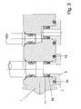
- the user side in Fig. 3 as well as the following figures shown below, the line 3 machined so that they have several steps to the end decreasing outside diameter has.
- the end the means at the stage with the smallest outer diameter, a first O-ring 5a, which is positioned by means of an auxiliary element 11.
- the Auxiliary member 11 is cylindrical, wherein between the stage with the smallest outer diameter and the auxiliary element 11 small, in the Fig. 3, not shown undercuts are provided, so that the Auxiliary element 11 frictionally and positively on the line 3 sits.
- the auxiliary element can also be shrunk or glued be attached to the line 3.
- the first O-ring 5a is here in radial direction against the substantially cylindrical part of the opening 2b pressed.
- the second O-ring 5b which compared with the first embodiment, has a significantly larger diameter than the first O-ring 5a, is arranged frontally in an annular groove 12 which in the expansion valve 1 is formed and which is closed by a flange 7 of the line 3. He is pressed in the axial direction against the expansion valve 1.
- both the evaporator side as well as user side instead of the second O-ring 5b a Flat gasket 5b 'used, wherein the flange 7 of the line 3, the flat gasket 5b 'presses into an annular recess in the expansion valve 1.
- the arrangement of the first O-ring 5a corresponds to that of the first embodiment.
- Fig. 5 According to the fourth embodiment shown in Fig. 5 are again two O-rings 5a and 5b provided as sealing elements, wherein the arrangement the first O-ring 5a corresponds to that of the first embodiment.
- the second O-ring 5b which has an inner diameter, which is slightly larger than the diameter of the opening 2a and 2b, is in one annular recess disposed in the expansion valve 1, wherein he from a flange 7 of the line 3 against the same opposite Surface of the recess is pressed.
- the second O-ring 5b is located here only on the end-side end face of the flange 7 and not on the outer circumferential surface the line 3.
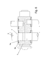
- Fig. 6 shows the fifth embodiment according to the two O-rings 5a and 5b are arranged approximately coaxially to each other, what for the outer, second O-ring 5b an annular groove on the end face of the expansion valve 1 is provided and it by a flange 7 of the line 3 in the direction of the groove bottom is pressed.
- the inner, first O-ring 5a is located on Transition between flange 7 and outer circumferential surface of the line 3 as well a rounded transition from a first to a second stage (See ring 5b of the first embodiment).
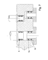
- the sixth embodiment shown in Fig. 7 provides an arrangement two identical O-rings 5a and 5b in succession in two corresponding beads 8 (evaporator side) or annular grooves (user side) in front.
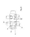
- the seventh embodiment shown in Fig. 8 corresponds the arrangement of the second O-ring 5b of the first embodiment.
- the first O-ring 5a is in a on the inner circumferential surface of the opening 2a and 2b provided annular groove 13 and arranged the end of the line 3 has no bead 8, but runs without significant changes in diameter until the rounded end.
- the O-ring 5a of the groove bottom of the annular groove 13 and the outer circumferential surface of the conduit 3 compressed, so that leakage can be prevented.
- CO 2 (R 744) is used as the refrigerant.
- a flat gasket 5b ' is used instead of the second O-ring 5b, wherein the flange 7 of the conduit 3 forms the flat gasket 5b' into an annular recess in the expansion organ 1 presses.
- the arrangement of the first O-ring 5a corresponds to that of the first embodiment.
- the sealing elements in this case are metallic seals.
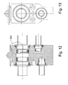
- Figures 9 to 11 show an expansion valve 1 with four connected Refrigerant lines 3, namely a motor-chamber-side suction line 3a, an evaporator-side suction line 3b, a motor-space-side pressure line 3c and an evaporator-side pressure line 3d.
- Refrigerant lines 3 namely a motor-chamber-side suction line 3a, an evaporator-side suction line 3b, a motor-space-side pressure line 3c and an evaporator-side pressure line 3d.
- the sealing effect is according to the ninth embodiment each means a sealing arrangement with two sealing elements 4, in the present two O-rings 5, namely a diagonal, i. obliquely to the longitudinal axis of Line loaded, spaced from the end of the line 3 arranged O-ring 5b and a radial, i. in the radial direction to the longitudinal axis of Line 3 loaded, closer to the line end arranged O-ring 5a causes.
- a guide element in this case a guide ring 14 made of plastic, provided at the line end, which ensures the centering.
- the guide ring 14 protects during assembly, the two sealing surfaces of the expansion valve 1 from mechanical damage.
- the conduit 3 is deformed in its end region such that the inner diameter at least that of the further course of the line 3, so that the hydraulically effective diameter in the area of the connection not reduced.
- the production takes place as follows: Outgoing From the line inside diameter Di, the line is first on a larger inner diameter D1 expanded, then a flange 7 is formed with an outer diameter D2. To record of the radial O-ring 5a, the line end becomes the line inner diameter D3, which is greater than or equal to the line internal diameter Di is brought and widened somewhat at the end of the line, whereby also a kind Chamfer for receiving the guide ring 14 on the outer circumference of the line end is molded.
- the inner diameter profile of the expansion valve 1 is the following, wherein the description from inside to outside takes place: after an area 15 with constant diameter follows, connected via a transition radius 16 a conical region 17 with outwardly enlarging diameter, the angle between the conical region 17 and the longitudinal axis of the pipe 5 ° to 30 °. This is followed by a transition area, a second conical region 18, wherein the angle between the second conical Range 18 and the line longitudinal axis is 2 ° to 20 °, and a in a radius widening outward area 19, the tangential to connects the second conical region 18.
- the radius of the outward flared portion 19 is 2% to 30% of the tube outer diameter.
- the radius of the outwardly widening portion 19 goes into one Contact surface 20 for the flange 7 via.
- the fixation of the line 3 in the expansion valve 1 can not by means of a shown holding plate, which, for example, with screws is connected to the expansion valve 1.
- the line 3 is transformed according to the variant in its end region such that the inner diameter also at least the other Course of the line 3 corresponds, so that also in this variant of the hydraulic effective diameter in the area of the connection is not reduced becomes.
- the production takes place as follows: Starting from the inner diameter of the pipe Di is the pipe first on an outside diameter D2 expanded, then a flange 7 with a corresponding outer diameter D2 shaped. The line 3 goes to the flange 7 in a Conduit diameter D4 over.
- the line end on the line inner diameter D3 the greater than or equal to the line internal diameter Di but smaller than that Line internal diameter D4 is brought and something at the line end widened, in turn, a kind of chamfer for receiving the guide ring 14 is formed.
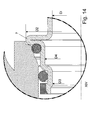
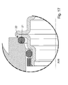
- FIGS. 15 to 17 corresponds to the shape of the line 3 and the manufacture of the of the ninth embodiment, wherein also an embodiment according to the variant of the ninth embodiment is possible.
- the outside is arranged O-ring 5b not a diagonal sealing element, but an axial Sealing element, i. it is in the direction of the pipe longitudinal axis with the help of Flange 7 against its substantially in the radial direction with respect to the Line longitudinal axis extending contact surface pressed.
- the inner diameter profile of the expansion valve 1 is the following, wherein the description from inside to outside takes place: after an area 15 with constant diameter follows, connected via a transition radius 16 a conical region 17 with outwardly enlarging diameter, the angle between the conical region 17 and the longitudinal axis of the pipe 5 ° to 30 °. This is followed by a transition area. It follows a region extending in the radial direction to the longitudinal axis of the line area 21, a vertical, i.
Landscapes
- Engineering & Computer Science (AREA)
- General Engineering & Computer Science (AREA)
- Mechanical Engineering (AREA)
- Physics & Mathematics (AREA)
- Thermal Sciences (AREA)
- Gasket Seals (AREA)
- Electroluminescent Light Sources (AREA)
- Structures Or Materials For Encapsulating Or Coating Semiconductor Devices Or Solid State Devices (AREA)
Abstract
Description
- Fig. 1
- eine perspektivische Ansicht einer Dichtungsanordnung in teilweiser Explosionsdarstellung gemäß dem ersten Ausführungsbeispiel,
- Fig. 2
- einen Schnitt durch die Dichtungsanordnung von Fig. 1,
- Fig. 3
- einen Schnitt durch eine Dichtungsanordnung gemäß dem zweiten Ausführungsbeispiel,
- Fig. 4
- einen Schnitt durch eine Dichtungsanordnung gemäß dem dritten Ausführungsbeispiel,
- Fig. 5
- einen Schnitt durch eine Dichtungsanordnung gemäß dem vierten Ausführungsbeispiel,
- Fig. 6
- einen Schnitt durch eine Dichtungsanordnung gemäß dem fünften Ausführungsbeispiel,
- Fig. 7
- einen Schnitt durch eine Dichtungsanordnung gemäß dem sechsten Ausführungsbeispiel,
- Fig. 8
- einen Schnitt durch eine Dichtungsanordnung gemäß dem siebten Ausführungsbeispiel,
- Fig. 9
- einen Schnitt durch ein Expansionsventil mit vier Leitungen mit Dichtungsanordnungen gemäß dem neunten Ausführungsbeispiel,
- Fig. 10
- eine Seitenansicht des Expansionsventils von Fig. 9 ohne Darstellung der Leitungen,
- Fig. 11
- einen Schnitt durch eine der Dichtungsanordnungen von Fig. 9, wobei die Dichtelemente unverformt dargestellt sind,
- Fig. 12
- einen Schnitt durch ein Expansionsventil mit vier Leitungen mit Dichtungsanordnungen gemäß der Variante des neunten Ausführungsbeispiels,
- Fig. 13
- eine Seitenansicht des Expansionsventils von Fig. 12 ohne Darstellung der Leitungen,
- Fig. 14
- einen Schnitt durch eine der Dichtungsanordnungen von Fig. 12, wobei die Dichtelemente unverformt dargestellt sind,
- Fig. 15
- einen Schnitt durch ein Expansionsventil mit vier Leitungen mit Dichtungsanordnungen gemäß dem zehnten Ausführungsbeispiel,
- Fig. 16
- eine Seitenansicht des Expansionsventils von Fig. 15 ohne Darstellung der Leitungen, und
- Fig. 17
- einen Schnitt durch eine der Dichtungsanordnungen von Fig. 15, wobei die Dichtelemente unverformt dargestellt sind.
- 1
- Expansionsventil, Expansionsorgan
- 2a, 2b
- Öffnung
- 3
- Leitung
- 4
- Dichtelement
- 5, 5a, 5b
- O-Ring
- 5b'
- Flachdichtung
- 6
- Dichtungsanordnung
- 7
- Flansch
- 8
- Sicke
- 11
- Hilfselement
- 12
- Ringnut
- 13
- Ringnut
- 14
- Führungsring
- 15
- Bereich
- 16
- Übergangsradius
- 17
- konischer Bereich
- 18
- zweiter konischer Bereich
- 19
- Bereich
- 20
- Anlagefläche
- 21
- Bereich
- 22
- Bereich
- Di
- Leitungsinnendurchmesser
- D1
- Leitungsinnendurchmesser
- D2
- Außendurchmesser
- D3
- Leitungsinnendurchmesser
- D4
- Leitungsinnendurchmesser
Claims (18)
- Dichtungsanordnung für einen Anschluss einer Leitung (3) an einem Bauteil, insbesondere einem Expansionsorgan (1) einer Kraftfahrzeug-Klimaanlage, mit einem Dichtelement (4), dadurch gekennzeichnet, dass zwei oder mehr Dichtelemente (4) zwischen der Leitung (3) und dem Bauteil vorgesehen sind.
- Dichtungsanordnung nach Anspruch 1, dadurch gekennzeichnet, dass mindestens eines der Dichtelemente (4) ein O-Ring (5; 5a; 5b) ist.
- Dichtungsanordnung nach Anspruch 1 oder 2, dadurch gekennzeichnet, dass mindestens eines der Dichtelemente (4) eine Flachdichtung (5b') oder eine Profildichtung ist.
- Dichtungsanordnung nach einem der vorhergehenden Ansprüche, dadurch gekennzeichnet, dass mindestens ein Dichtelement (4) in einer am Außenumfang der Leitung vorgesehen Sicke (8) oder Nut angeordnet ist.
- Dichtungsanordnung nach einem der vorhergehenden Ansprüche, dadurch gekennzeichnet, dass mindestens ein Dichtelement (4) in Anlage an einem am Außenumfang der Leitung vorgesehen Flansch (7) ist.
- Dichtungsanordnung nach einem der vorhergehenden Ansprüche, dadurch gekennzeichnet, dass mindestens ein Dichtelement (4) am Außenumfang der Leitung (3) angeordnet und in Anlage an einem am Außenumfang der Leitung vorgesehen Flansch (7) ist.
- Dichtungsanordnung nach einem der vorhergehenden Ansprüche, dadurch gekennzeichnet, dass ein Dichtelement (4) in einer an der Stirnfläche des Bauteils vorgesehenen Ringnut (12) angeordnet ist.
- Dichtungsanordnung nach einem der vorhergehenden Ansprüche, dadurch gekennzeichnet, dass ein Dichtelement (4) in einer an der Innenmantelfläche des Bauteils vorgesehenen Ringnut (13) angeordnet ist.
- Dichtungsanordnung nach einem der vorhergehenden Ansprüche, dadurch gekennzeichnet, dass mindestens zwei der Dichtelemente (4) in unterschiedlicher Richtung abdichten.
- Dichtungsanordnung nach einem der vorhergehenden Ansprüche, dadurch gekennzeichnet, dass mehrere insbesondere hintereinander angeordnete Dichtelemente in gleicher Richtung abdichten.
- Dichtungsanordnung nach einem der vorhergehenden Ansprüche, dadurch gekennzeichnet, dass ein Dichtelement (4) einen Dichtspalt in axialer Richtung und ein Dichtelement (4) einen Dichtspalt in radialer Richtung bezüglich der Leitung (3) abdichtet.
- Dichtungsanordnung nach einem der vorhergehenden Ansprüche, dadurch gekennzeichnet, dass ein Dichtelement (4) einen Dichtspalt in schräger Richtung bezüglich der Leitung (3) abdichtet.
- Dichtungsanordnung nach einem der vorhergehenden Ansprüche, dadurch gekennzeichnet, dass ein Dichtelement (4) mittels eines Hilfselements (11) positioniert ist.
- Dichtungsanordnung nach einem der vorhergehenden Ansprüche, dadurch gekennzeichnet, dass die Übergänge zwischen einzelnen Stufen mit unterschiedlichen Durchmessern abgerundet sind.
- Dichtungsanordnung nach einem der vorhergehenden Ansprüche, dadurch gekennzeichnet, mindestens ein metallisches Dichtelement und/oder ein Dichtelement aus EPDM oder HNBR Teil der Dichtungsanordnung (6) ist.
- Dichtungsanordnung nach einem der vorhergehenden Ansprüche, dadurch gekennzeichnet, in einem Leitungsendbereich ein Führungselement angeordnet ist.
- Dichtungsanordnung nach Anspruch 15, dadurch gekennzeichnet, dass das Führungselement ein Führungsring (14) ist, welcher eine dem Außenumfang des Leitungsendbereichs entsprechende Innenkontur aufweist, wobei sich der Außenumfang des Leitungsendbereichs zum Leitungsende hin verkleinert.
- Dichtungsanordnung nach einem der vorhergehenden Ansprüche, dadurch gekennzeichnet, dass eine innere Querschnittsfläche der Dichtungsanordnung so groß wie oder größer als eine innere Querschnittsfläche der Leitung und/oder des Bauteils ist.
Applications Claiming Priority (2)
| Application Number | Priority Date | Filing Date | Title |
|---|---|---|---|
| DE10361109 | 2003-12-22 | ||
| DE10361109 | 2003-12-22 |
Publications (2)
| Publication Number | Publication Date |
|---|---|
| EP1548348A1 true EP1548348A1 (de) | 2005-06-29 |
| EP1548348B1 EP1548348B1 (de) | 2009-01-21 |
Family
ID=34530387
Family Applications (1)
| Application Number | Title | Priority Date | Filing Date |
|---|---|---|---|
| EP04028067A Expired - Lifetime EP1548348B1 (de) | 2003-12-22 | 2004-11-26 | Dichtungsanordnung, insbesondere für einen Anschluss einer Leitung an einem Expansionsorgan |
Country Status (3)
| Country | Link |
|---|---|
| EP (1) | EP1548348B1 (de) |
| AT (1) | ATE421660T1 (de) |
| DE (2) | DE502004008908D1 (de) |
Cited By (3)
| Publication number | Priority date | Publication date | Assignee | Title |
|---|---|---|---|---|
| WO2008058597A1 (de) * | 2006-11-16 | 2008-05-22 | Hydac Process Technology Gmbh | Kupplungsvorrichtung |
| EP2077410A1 (de) | 2008-01-02 | 2009-07-08 | Voss Automotive GmbH | Verbindungssystem für fluidführende Systeme |
| US20220235891A1 (en) * | 2021-01-25 | 2022-07-28 | Hutchinson Fluid Management Systems, Inc. | Dual plane seal air conditioner connector |
Families Citing this family (3)
| Publication number | Priority date | Publication date | Assignee | Title |
|---|---|---|---|---|
| DE102012203279A1 (de) | 2012-03-01 | 2013-09-05 | Behr Gmbh & Co. Kg | Verbindungsstück |
| DE202012103763U1 (de) | 2012-10-01 | 2012-10-24 | Behr Gmbh & Co. Kg | Rohr |
| CN107487150B (zh) * | 2017-07-04 | 2021-07-09 | 新昌县欣驰机械有限公司 | 一种高性能汽车空调系统用连接块及其制造方法 |
Citations (5)
| Publication number | Priority date | Publication date | Assignee | Title |
|---|---|---|---|---|
| DE2510208A1 (de) * | 1975-03-08 | 1976-09-09 | Mengeringhausen Max | Muffenrohr-verbindung |
| GB1559623A (en) * | 1976-02-16 | 1980-01-23 | Ekman K R | Coupling arrangement for fluid flow |
| EP0916886A2 (de) * | 1997-11-17 | 1999-05-19 | MURRAY EUROPE S.p.A. | Verbindungsstück für Rohrleitungen |
| US6260851B1 (en) * | 1995-10-30 | 2001-07-17 | Manuli Auto France | Composite gasket and assembly comprising such a gasket |
| US20030214130A1 (en) * | 2002-05-20 | 2003-11-20 | Schroeder Fred Georg | Air conditioning block fitting with two surface sealing |
-
2004
- 2004-11-26 DE DE502004008908T patent/DE502004008908D1/de not_active Expired - Lifetime
- 2004-11-26 EP EP04028067A patent/EP1548348B1/de not_active Expired - Lifetime
- 2004-11-26 DE DE102004057408A patent/DE102004057408A1/de not_active Withdrawn
- 2004-11-26 AT AT04028067T patent/ATE421660T1/de not_active IP Right Cessation
Patent Citations (5)
| Publication number | Priority date | Publication date | Assignee | Title |
|---|---|---|---|---|
| DE2510208A1 (de) * | 1975-03-08 | 1976-09-09 | Mengeringhausen Max | Muffenrohr-verbindung |
| GB1559623A (en) * | 1976-02-16 | 1980-01-23 | Ekman K R | Coupling arrangement for fluid flow |
| US6260851B1 (en) * | 1995-10-30 | 2001-07-17 | Manuli Auto France | Composite gasket and assembly comprising such a gasket |
| EP0916886A2 (de) * | 1997-11-17 | 1999-05-19 | MURRAY EUROPE S.p.A. | Verbindungsstück für Rohrleitungen |
| US20030214130A1 (en) * | 2002-05-20 | 2003-11-20 | Schroeder Fred Georg | Air conditioning block fitting with two surface sealing |
Cited By (3)
| Publication number | Priority date | Publication date | Assignee | Title |
|---|---|---|---|---|
| WO2008058597A1 (de) * | 2006-11-16 | 2008-05-22 | Hydac Process Technology Gmbh | Kupplungsvorrichtung |
| EP2077410A1 (de) | 2008-01-02 | 2009-07-08 | Voss Automotive GmbH | Verbindungssystem für fluidführende Systeme |
| US20220235891A1 (en) * | 2021-01-25 | 2022-07-28 | Hutchinson Fluid Management Systems, Inc. | Dual plane seal air conditioner connector |
Also Published As
| Publication number | Publication date |
|---|---|
| ATE421660T1 (de) | 2009-02-15 |
| EP1548348B1 (de) | 2009-01-21 |
| DE102004057408A1 (de) | 2005-07-21 |
| DE502004008908D1 (de) | 2009-03-12 |
Similar Documents
| Publication | Publication Date | Title |
|---|---|---|
| DE69220502T2 (de) | Hydraulische anschluszstücke | |
| DE10261887B4 (de) | Rohrkupplung | |
| EP0163252B1 (de) | Rohrverschraubung mit Berührungsdichtung | |
| EP0992717A2 (de) | Flachdichtungsring | |
| WO2023079077A1 (de) | Verfahren zur herstellung eines dichtrings sowie dichtring | |
| DE10234615B4 (de) | Bördelverbindungsbaugruppe für Klimatisierungsanlagen von Kraftfahrzeugen | |
| DE3428260A1 (de) | Rohrverbindung | |
| DE3909424C1 (de) | ||
| EP0295479A1 (de) | Dichtverbindung | |
| DE102007035222A1 (de) | Flanschverbindung | |
| EP1548348B1 (de) | Dichtungsanordnung, insbesondere für einen Anschluss einer Leitung an einem Expansionsorgan | |
| DE19507736B4 (de) | Dichtungselement | |
| DE102006050723A1 (de) | Entlüftungsventil, insbesondere für Verschlussschraube | |
| EP3183481B1 (de) | Dichtungsring zum axialen abdichten von zwei axial relativ zueinander beweglich angeordneten teilen und dichtungssystem mit dem dichtungsring | |
| DE10163931A1 (de) | Rohrkupplung | |
| DE102006029645A1 (de) | Kältemittelleitung, insbesondere für mit CO2 betriebene Kraftfahrzeugklimaanlagen | |
| DE69407283T2 (de) | Befestigungseinheit für ein rohr und ein verfahren zu deren herstellung | |
| DE102005056023B3 (de) | Wellrohrschlaucharmatur und Anschlussverfahren | |
| EP2077410B1 (de) | Verbindungssystem für fluidführende Systeme | |
| EP0049824B1 (de) | Druckgefäss, insbesondere Druckakkumulator für Druckmittelkreise | |
| DE19855795B4 (de) | Schneidringverschraubung für Druckmittel-Rohrleitungen | |
| DE102013015895A1 (de) | Pressfitting und Verbindungsanordnung mit einem solchen Pressfitting | |
| DE102022134801A1 (de) | Restdruckhalteventil für eine Gasdruckfeder | |
| EP1236945B1 (de) | Rohrverbindung mit einem umgeformten Rohr | |
| EP0691505B1 (de) | Anschlussvorrichtung für Druckleitungen |
Legal Events
| Date | Code | Title | Description |
|---|---|---|---|
| PUAI | Public reference made under article 153(3) epc to a published international application that has entered the european phase |
Free format text: ORIGINAL CODE: 0009012 |
|
| AK | Designated contracting states |
Kind code of ref document: A1 Designated state(s): AT BE BG CH CY CZ DE DK EE ES FI FR GB GR HU IE IS IT LI LU MC NL PL PT RO SE SI SK TR |
|
| AX | Request for extension of the european patent |
Extension state: AL HR LT LV MK YU |
|
| 17P | Request for examination filed |
Effective date: 20051229 |
|
| AKX | Designation fees paid |
Designated state(s): AT BE BG CH CY CZ DE DK EE ES FI FR GB GR HU IE IS IT LI LU MC NL PL PT RO SE SI SK TR |
|
| 17Q | First examination report despatched |
Effective date: 20060221 |
|
| GRAP | Despatch of communication of intention to grant a patent |
Free format text: ORIGINAL CODE: EPIDOSNIGR1 |
|
| GRAS | Grant fee paid |
Free format text: ORIGINAL CODE: EPIDOSNIGR3 |
|
| GRAA | (expected) grant |
Free format text: ORIGINAL CODE: 0009210 |
|
| AK | Designated contracting states |
Kind code of ref document: B1 Designated state(s): AT BE BG CH CY CZ DE DK EE ES FI FR GB GR HU IE IS IT LI LU MC NL PL PT RO SE SI SK TR |
|
| REG | Reference to a national code |
Ref country code: GB Ref legal event code: FG4D Free format text: NOT ENGLISH |
|
| REG | Reference to a national code |
Ref country code: CH Ref legal event code: EP |
|
| REG | Reference to a national code |
Ref country code: IE Ref legal event code: FG4D Free format text: LANGUAGE OF EP DOCUMENT: GERMAN |
|
| REF | Corresponds to: |
Ref document number: 502004008908 Country of ref document: DE Date of ref document: 20090312 Kind code of ref document: P |
|
| PG25 | Lapsed in a contracting state [announced via postgrant information from national office to epo] |
Ref country code: NL Free format text: LAPSE BECAUSE OF FAILURE TO SUBMIT A TRANSLATION OF THE DESCRIPTION OR TO PAY THE FEE WITHIN THE PRESCRIBED TIME-LIMIT Effective date: 20090121 |
|
| NLV1 | Nl: lapsed or annulled due to failure to fulfill the requirements of art. 29p and 29m of the patents act | ||
| PG25 | Lapsed in a contracting state [announced via postgrant information from national office to epo] |
Ref country code: FI Free format text: LAPSE BECAUSE OF FAILURE TO SUBMIT A TRANSLATION OF THE DESCRIPTION OR TO PAY THE FEE WITHIN THE PRESCRIBED TIME-LIMIT Effective date: 20090121 Ref country code: ES Free format text: LAPSE BECAUSE OF FAILURE TO SUBMIT A TRANSLATION OF THE DESCRIPTION OR TO PAY THE FEE WITHIN THE PRESCRIBED TIME-LIMIT Effective date: 20090502 Ref country code: SI Free format text: LAPSE BECAUSE OF FAILURE TO SUBMIT A TRANSLATION OF THE DESCRIPTION OR TO PAY THE FEE WITHIN THE PRESCRIBED TIME-LIMIT Effective date: 20090121 |
|
| REG | Reference to a national code |
Ref country code: IE Ref legal event code: FD4D |
|
| PG25 | Lapsed in a contracting state [announced via postgrant information from national office to epo] |
Ref country code: PL Free format text: LAPSE BECAUSE OF FAILURE TO SUBMIT A TRANSLATION OF THE DESCRIPTION OR TO PAY THE FEE WITHIN THE PRESCRIBED TIME-LIMIT Effective date: 20090121 Ref country code: PT Free format text: LAPSE BECAUSE OF FAILURE TO SUBMIT A TRANSLATION OF THE DESCRIPTION OR TO PAY THE FEE WITHIN THE PRESCRIBED TIME-LIMIT Effective date: 20090622 Ref country code: SE Free format text: LAPSE BECAUSE OF FAILURE TO SUBMIT A TRANSLATION OF THE DESCRIPTION OR TO PAY THE FEE WITHIN THE PRESCRIBED TIME-LIMIT Effective date: 20090421 Ref country code: IS Free format text: LAPSE BECAUSE OF FAILURE TO SUBMIT A TRANSLATION OF THE DESCRIPTION OR TO PAY THE FEE WITHIN THE PRESCRIBED TIME-LIMIT Effective date: 20090521 |
|
| PG25 | Lapsed in a contracting state [announced via postgrant information from national office to epo] |
Ref country code: DK Free format text: LAPSE BECAUSE OF FAILURE TO SUBMIT A TRANSLATION OF THE DESCRIPTION OR TO PAY THE FEE WITHIN THE PRESCRIBED TIME-LIMIT Effective date: 20090121 Ref country code: IE Free format text: LAPSE BECAUSE OF FAILURE TO SUBMIT A TRANSLATION OF THE DESCRIPTION OR TO PAY THE FEE WITHIN THE PRESCRIBED TIME-LIMIT Effective date: 20090121 Ref country code: EE Free format text: LAPSE BECAUSE OF FAILURE TO SUBMIT A TRANSLATION OF THE DESCRIPTION OR TO PAY THE FEE WITHIN THE PRESCRIBED TIME-LIMIT Effective date: 20090121 Ref country code: CZ Free format text: LAPSE BECAUSE OF FAILURE TO SUBMIT A TRANSLATION OF THE DESCRIPTION OR TO PAY THE FEE WITHIN THE PRESCRIBED TIME-LIMIT Effective date: 20090121 |
|
| PLBE | No opposition filed within time limit |
Free format text: ORIGINAL CODE: 0009261 |
|
| STAA | Information on the status of an ep patent application or granted ep patent |
Free format text: STATUS: NO OPPOSITION FILED WITHIN TIME LIMIT |
|
| PG25 | Lapsed in a contracting state [announced via postgrant information from national office to epo] |
Ref country code: SK Free format text: LAPSE BECAUSE OF FAILURE TO SUBMIT A TRANSLATION OF THE DESCRIPTION OR TO PAY THE FEE WITHIN THE PRESCRIBED TIME-LIMIT Effective date: 20090121 Ref country code: RO Free format text: LAPSE BECAUSE OF FAILURE TO SUBMIT A TRANSLATION OF THE DESCRIPTION OR TO PAY THE FEE WITHIN THE PRESCRIBED TIME-LIMIT Effective date: 20090121 |
|
| 26N | No opposition filed |
Effective date: 20091022 |
|
| PG25 | Lapsed in a contracting state [announced via postgrant information from national office to epo] |
Ref country code: BG Free format text: LAPSE BECAUSE OF FAILURE TO SUBMIT A TRANSLATION OF THE DESCRIPTION OR TO PAY THE FEE WITHIN THE PRESCRIBED TIME-LIMIT Effective date: 20090421 |
|
| BERE | Be: lapsed |
Owner name: BEHR G.M.B.H. & CO. KG Effective date: 20091130 |
|
| PG25 | Lapsed in a contracting state [announced via postgrant information from national office to epo] |
Ref country code: MC Free format text: LAPSE BECAUSE OF NON-PAYMENT OF DUE FEES Effective date: 20091130 |
|
| REG | Reference to a national code |
Ref country code: CH Ref legal event code: PL |
|
| GBPC | Gb: european patent ceased through non-payment of renewal fee |
Effective date: 20091126 |
|
| PG25 | Lapsed in a contracting state [announced via postgrant information from national office to epo] |
Ref country code: LI Free format text: LAPSE BECAUSE OF NON-PAYMENT OF DUE FEES Effective date: 20091130 Ref country code: BE Free format text: LAPSE BECAUSE OF NON-PAYMENT OF DUE FEES Effective date: 20091130 Ref country code: CH Free format text: LAPSE BECAUSE OF NON-PAYMENT OF DUE FEES Effective date: 20091130 Ref country code: GR Free format text: LAPSE BECAUSE OF FAILURE TO SUBMIT A TRANSLATION OF THE DESCRIPTION OR TO PAY THE FEE WITHIN THE PRESCRIBED TIME-LIMIT Effective date: 20090422 |
|
| PG25 | Lapsed in a contracting state [announced via postgrant information from national office to epo] |
Ref country code: GB Free format text: LAPSE BECAUSE OF NON-PAYMENT OF DUE FEES Effective date: 20091126 |
|
| PG25 | Lapsed in a contracting state [announced via postgrant information from national office to epo] |
Ref country code: AT Free format text: LAPSE BECAUSE OF NON-PAYMENT OF DUE FEES Effective date: 20091126 |
|
| PGFP | Annual fee paid to national office [announced via postgrant information from national office to epo] |
Ref country code: FR Payment date: 20101209 Year of fee payment: 7 |
|
| PG25 | Lapsed in a contracting state [announced via postgrant information from national office to epo] |
Ref country code: IT Free format text: LAPSE BECAUSE OF FAILURE TO SUBMIT A TRANSLATION OF THE DESCRIPTION OR TO PAY THE FEE WITHIN THE PRESCRIBED TIME-LIMIT Effective date: 20090121 |
|
| PG25 | Lapsed in a contracting state [announced via postgrant information from national office to epo] |
Ref country code: LU Free format text: LAPSE BECAUSE OF NON-PAYMENT OF DUE FEES Effective date: 20091126 |
|
| PG25 | Lapsed in a contracting state [announced via postgrant information from national office to epo] |
Ref country code: HU Free format text: LAPSE BECAUSE OF FAILURE TO SUBMIT A TRANSLATION OF THE DESCRIPTION OR TO PAY THE FEE WITHIN THE PRESCRIBED TIME-LIMIT Effective date: 20090722 |
|
| PG25 | Lapsed in a contracting state [announced via postgrant information from national office to epo] |
Ref country code: TR Free format text: LAPSE BECAUSE OF FAILURE TO SUBMIT A TRANSLATION OF THE DESCRIPTION OR TO PAY THE FEE WITHIN THE PRESCRIBED TIME-LIMIT Effective date: 20090121 |
|
| PG25 | Lapsed in a contracting state [announced via postgrant information from national office to epo] |
Ref country code: CY Free format text: LAPSE BECAUSE OF FAILURE TO SUBMIT A TRANSLATION OF THE DESCRIPTION OR TO PAY THE FEE WITHIN THE PRESCRIBED TIME-LIMIT Effective date: 20090121 |
|
| REG | Reference to a national code |
Ref country code: FR Ref legal event code: ST Effective date: 20120731 |
|
| PG25 | Lapsed in a contracting state [announced via postgrant information from national office to epo] |
Ref country code: FR Free format text: LAPSE BECAUSE OF NON-PAYMENT OF DUE FEES Effective date: 20111130 |
|
| REG | Reference to a national code |
Ref country code: DE Ref legal event code: R082 Ref document number: 502004008908 Country of ref document: DE Representative=s name: GRAUEL, ANDREAS, DIPL.-PHYS. DR. RER. NAT., DE |
|
| REG | Reference to a national code |
Ref country code: DE Ref legal event code: R082 Ref document number: 502004008908 Country of ref document: DE Representative=s name: GRAUEL, ANDREAS, DIPL.-PHYS. DR. RER. NAT., DE Effective date: 20150324 Ref country code: DE Ref legal event code: R081 Ref document number: 502004008908 Country of ref document: DE Owner name: MAHLE INTERNATIONAL GMBH, DE Free format text: FORMER OWNER: BEHR GMBH & CO. KG, 70469 STUTTGART, DE Effective date: 20150324 |
|
| PGFP | Annual fee paid to national office [announced via postgrant information from national office to epo] |
Ref country code: DE Payment date: 20181203 Year of fee payment: 15 |
|
| REG | Reference to a national code |
Ref country code: DE Ref legal event code: R119 Ref document number: 502004008908 Country of ref document: DE |
|
| PG25 | Lapsed in a contracting state [announced via postgrant information from national office to epo] |
Ref country code: DE Free format text: LAPSE BECAUSE OF NON-PAYMENT OF DUE FEES Effective date: 20200603 |