EP0916886A2 - Fitting for fluid conveying pipings - Google Patents
Fitting for fluid conveying pipings Download PDFInfo
- Publication number
- EP0916886A2 EP0916886A2 EP98121096A EP98121096A EP0916886A2 EP 0916886 A2 EP0916886 A2 EP 0916886A2 EP 98121096 A EP98121096 A EP 98121096A EP 98121096 A EP98121096 A EP 98121096A EP 0916886 A2 EP0916886 A2 EP 0916886A2
- Authority
- EP
- European Patent Office
- Prior art keywords
- tubular
- mouth
- groove
- toric
- fitting according
- Prior art date
- Legal status (The legal status is an assumption and is not a legal conclusion. Google has not performed a legal analysis and makes no representation as to the accuracy of the status listed.)
- Granted
Links
Images

Classifications
-
- F—MECHANICAL ENGINEERING; LIGHTING; HEATING; WEAPONS; BLASTING
- F16—ENGINEERING ELEMENTS AND UNITS; GENERAL MEASURES FOR PRODUCING AND MAINTAINING EFFECTIVE FUNCTIONING OF MACHINES OR INSTALLATIONS; THERMAL INSULATION IN GENERAL
- F16L—PIPES; JOINTS OR FITTINGS FOR PIPES; SUPPORTS FOR PIPES, CABLES OR PROTECTIVE TUBING; MEANS FOR THERMAL INSULATION IN GENERAL
- F16L23/00—Flanged joints
- F16L23/16—Flanged joints characterised by the sealing means
- F16L23/18—Flanged joints characterised by the sealing means the sealing means being rings
-
- F—MECHANICAL ENGINEERING; LIGHTING; HEATING; WEAPONS; BLASTING
- F16—ENGINEERING ELEMENTS AND UNITS; GENERAL MEASURES FOR PRODUCING AND MAINTAINING EFFECTIVE FUNCTIONING OF MACHINES OR INSTALLATIONS; THERMAL INSULATION IN GENERAL
- F16L—PIPES; JOINTS OR FITTINGS FOR PIPES; SUPPORTS FOR PIPES, CABLES OR PROTECTIVE TUBING; MEANS FOR THERMAL INSULATION IN GENERAL
- F16L21/00—Joints with sleeve or socket
- F16L21/02—Joints with sleeve or socket with elastic sealing rings between pipe and sleeve or between pipe and socket, e.g. with rolling or other prefabricated profiled rings
- F16L21/035—Joints with sleeve or socket with elastic sealing rings between pipe and sleeve or between pipe and socket, e.g. with rolling or other prefabricated profiled rings placed around the spigot end before connection
Definitions
- the present invention relates to a fitting for fluid conveying pipings.
- the present invention relates to a fitting for conveying pressurised fluids, of the quick-fitting type, particularly useful in motor-cars sector.
- Known embodiments of the concerned fittings provide for the formation of metal bells or cups or the like, realised near to the mouth of one of the tubular coupling bodies.
- the coupling of the two tubular bodies is obtained by pressure-fitting by hand of a tubular body into the bell or cup of the other tubular body.
- the tightness of the fitting is ensured by one or more toric rings or sealing gaskets obtained on the tubular body which couples with the second bell- or cup-shaped tubular body.
- the toric rings or sealing gaskets are housed in respective grooves obtained on either of the tubular bodies of the fitting.
- Object of this invention is to obviate the aforesaid drawbacks.
- object of this invention is to provide a fitting for fluids conveying pipings, in particular pressurised fluids, especially of the quick-fitting type, wherein the tightness needs being particularly effective and lasting in the time, such as not to involve complicated working operations and such as to obtain reliable results in the time.
- a further object of the invention is to avoid to increase the length of the tubular body to create the space sufficient to provide grooves to insert corresponding toric rings or sealing gaskets, in order to reduce the amount of material utilised and therefore the production costs, and besides to avoid assembly and interface problems of said tubular body with other elements constituting the fluid conveying system.
- a further object of the invention is to provide a fitting for pressurised fluid conveying of easy and economical realisation, suitable to be used in servomechanism systems or in cooling circuits of motor-cars.
- the present invention allows to achieve these and still other objects which shall become clearer thanks to the following description, by providing a sealing gasket or a toric ring in correspondence of the mouth end of a tubular body and housing said ring or gasket in the conical flaring which the end of said body is provided with.
- Object of this invention is therefore a fitting for fluid conveying pipings comprising a first tubular female body provided at a free end with a flared or conical mouth, a second tubular male body, said tubular bodies being coupled and partly inserted into each other, and at least two grooves or seats for housing sealing gasket or toric rings, said grooves or seats being obtained along the faced surfaces of said tubular bodies, wherein one of said grooves or seats is placed in correspondence of the flared or conical mouth of the first tubular female body.
- the second tubular body is so shaped as to partly circumscribe said seat or groove.
- the seat for the sealing gasket or toric ring obtained in correspondence of the flared mouth of said beat surface is circumscribed by said mouth and a groove obtained near said beat surface.
- the second tubular body is obtained in one only piece, extended into said opening without gaps and is provided with at least two grooves or seats for housing sealing gaskets or toric rings, at least one of said seats being obtained in correspondence of the conical flaring of the first tubular female body and is circumscribed by one of said upsettings and/or by one of said flanges.
- the gasket or toric ring located in the seat corresponding to the flared conical mouth expands in said seat and exercises radial and longitudinal compressions along an inclined plane defined by the mouth, improving in this way the tightness of the fitting at high exercise pressures.
- Said coupling is an optimum one, as the toric ring or sealing gasket makes up for the possible tolerances that may exist between the two tubular bodies, expanding in all directions and causing therefore the fitting to be less sensitive to the possible variations in the diameter of the two tubular bodies.
- the fitting of the present invention is compatible with the known ones and may be used as a replacement for the latter ones, which, as is known, are provided with one only sealing toric ring, and require frequent replacements due to an imperfect or an insufficient sealing.
- the fitting for fluid conveying pipings of the present invention comprises:
- said first groove with the corresponding first toric sealing ring adjoins said first tubular rectilinear part; said second groove with the corresponding second toric sealing ring adjoins said conical flaring, and said flat beat surface of the tubular male body strikes said flat front part of the tubular female body.
- the fitting for fluid conveying pipings comprises a tubular female body and a tubular male body, partly superposed to one another and coupled by means of respective flanges circumscribed on at least a side by an upsetting formed on one of said tubular bodies, wherein at least one of said tubular bodies is obtained in one only piece, extending into the through-opening of the respective flange without gaps, and has at least two grooves or seats for housing sealing gaskets or toric rings, at least one of which is circumscribed on one side by one of said flanges or said upsettings.
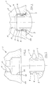
- the fitting for fluid conveying pipings of the present invention comprises a first tubular female body 2 and a second tubular male body 3.
- Said first tubular female body 2 has in its internal advanced portion a cup or bell-shaped configuration, circumscribed, from the front to the back part, by a flat front 14, a conic flaring 12, a first tubular rectilinear part 10, a tapering or neck 13, and a second tubular rectilinear part 11.
- Said first 10 and said second 11 tubular rectilinear parts are parallel arranged and co-axial to the longitudinal axis of the tubular female body 2.
- the tubular male body 3 has, in its external advanced part, a front mouth 6 slightly conically funnel-shaped and a back flat beat surface 7 spaced from said mouth 6. Mouth 6 and the flat beat surface 7 are united by a tubular part 15 provided with a first groove 4, in correspondence of said mouth 6, and a second groove 5 in correspondence of said flat beat surface 7.
- the first groove 4, which may have a rectangular section or a section of any other suitable shape, houses a first toric sealing ring 8; and the second groove 5, which also may have an essentially rectangular shape, houses a second toric sealing ring 9.
- said first groove 4 with the corresponding toric sealing ring 8 adjoins the first tubular rectilinear part 10 of body 2; while said second groove 5, with the corresponding toric sealing ring 9, is placed in correspondence of the conical flaring 12 of the same body.
- the flat surface 7 of the tubular male body 3 perfectly strikes the flat front 14 of said tubular female body 2.
- the first tubular rectilinear part 10 of the tubular female body 2 has an inner diameter slightly greater than the one of the tubular rectilinear part 15 of the tubular male body 3.
- the second tubular rectilinear part 11 of the tubular female body 2, of smaller size with respect to the first tubular rectilinear part 10, has an inner diameter equal to the inner diameter of the tubular male body 3.
- the external diameter of said first 8 and second 9 toric sealing rings is slightly greater respectively than the internal diameter of the first tubular rectilinear part 10 and the corresponding conical flaring 12 of the tubular female body 2.
- a locking and tightening means is fitted on (not shown in the figure) of the type of threaded ring nut or with a bayonet joint, which prevents the axial sliding of the two tubular bodies.
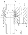
- FIG. 4 shows a second embodiment of the fitting of the present invention.
- Said fitting indicated by 1', comprises a first tubular female body 2' from metal, coupled and connected to a flange 18, also preferably from metal, and a second tubular male body 3' from metal, coupled and connected to a flange 17.
- Said flanges 17 an 18 are the connecting means of said box-shaped bodies 2' and 3'.
- At least one of the tubular bodies for instance the tubular male body 3', is constituted by a monobloc, being coupled and fastened to the respective flange 17 without gaps.
- Said tubular element has an external diameter complementary to that of the opening or through-hole formed in advance on flange 17 wherein it is inserted by hand or trough conventional automatic feed means.
- the tubular male body 3' is provided, respectively, with an upsetting 20 and a flared mouth zone 22, preferably obtained by means of like widening punches of like known means.
- the tubular male body 3' circumscribes a groove 24, suitable to constitute the housing seat of a first gasket or toric ring 26.
- Said flared mouth 22 in cooperation with the end of one of the sides of flange 16, in the case in point the front side indicated by 17', forms a further seat 22' for housing a second gasket or sealing toric ring 28.
- Said side 17' of flange 17 which is positioned near groove 24 of the tubular body 3', forms a strike shoulder for the first tubular female body 2', fitted on the second tubular body 3', starting from its end zone integrating said groove 24.
- the first tubular body 2' has obviously a diameter complementary to the external diameter of the tubular body 3', at least along the portion, indicated by 30 and rectilinearly extended, designed to superpose on the one whereon groove 24 is formed.
- flange 18 designed to couple with flange 17 of the second tubular body 3', is preferably free, i.e. it is simply fitted on said body without welding.
- Said flange 18 is shaped in advance by mechanical workings along its internal surface for the precise coupling with the advanced part of the tubular body 2' which comprises the end flaring 32, the rectilinear portion 30 and the subsequent tapering 34.
- Both flanges 17 and 18 are provided with through-holes, respectively indicated by 38 and 40, aligned to one another for the insertion of conventional locking bolts or like means.
- Fitting 1 of the present invention comprises therefore a second tubular body 3' in one only piece whereon two seats 22', 24 are obtained for as many gaskets or toric rings which ensure an optimum tightness.
- One of these seats namely seat 22', is formed beyond flange 17, tangentially to the same and in correspondence of the flared mouth 32 of the first tubular body 2'.
- the flared surface of mouth 32, the flared surface of the first tubular body 2' and the front side of flange 17 form the bearing surfaces of gasket 18.
- the dimensional elongation of the tubular body 12 is prevented, which would be necessary and unavoidable, were another seat realised of a conventional type, similar to groove 24.
- seat 22' Because of flarings 22 of the first tubular body 12, and 32 of the second tubular body 16, seat 22' has a substantially triangular configuration, without excluding the possibility for this seat to have a different conformation.
- FIG. 5 wherein the same numerals are maintained as the preceding Figure 4 as concern common parts or elements, schematically shows a further embodiment of the fitting of the present invention.
- the front end of the second tubular body 3'', indicated by 43 has an external diameter markedly smaller than the internal diameter of the first tubular body 2'' and beyond said end 43 a markedly extended upsetting 42 is formed.
- Flange 17, parallelly, has a stubbling 17'' to contain said upsetting.
- a shaped ring 44 is fitted on said end 43, in such a way as to adhere to upsetting 2.
- Said ring 44 which may be from metal, plastic or other suitable material, has an inner diameter complementary to the one of end 43 whereon it is fitted and a differentiated external diameter to form a stubbling 46, in correspondence of the flaring mouth of the first tubular body 2''.
- ring 44 is formed by a first sector whose maximum external diameter substantially corresponds to the internal diameter of the rectilinear portion 30 of the first tubular body 2'', and by a second and integral sector having an external diameter smaller with respect to that of the same portion 30. Ring 44 is fitted on end 43 of the tubular body 3'' with the smaller diameter sector oriented towards upsetting 42, which acts as a shoulder for the end flaring 32 of the first tubular body 2''.
- the first toric ring or gasket 28 is housed in seat 50 comprised between said flaring 32 of the first smaller diameter tubular body 2'' and the smaller diameter sector of ring 44, while upsetting 42 forms one of the containment surfaces and completes said seat 50.
- a second gasket or toric ring 52 is located near mouth 54 of the second tubular body 3''.
- Said ring 52 is fitted on end 43 of the tubular body 3'' and causes the further tightening between said body and the first tubular body 2''.
- Gasket 52 in fact, has such a section as to be suitably compressed by the internal surface of the rectilinear portion 30 of said first tubular body 2''.
- Mouth 54 of the second tubular body 3'' is suitably flared to prevent the accidental unthreading of gasket 52.
- the housing seat of said gasket 52 is therefore circumscribed by the shaped ring 44 and the end 43 of the second tubular body 3'' and is limited by the flared mouth 54.
- the presence of two toric rings or sealing gaskets 28 and 52 does not involve dimensional elongations of the second tubular body 3'', as it is upsetting 42 that constitutes one of the walls of seat 50 of gasket 28.
- the second tubular body 3'' is made, as in the preceding solution, in one only piece inserted in the through-opening of flange 17 and subsequently subjected to cold permanent sets to realise upsettings 20 and 42, the latter being more extended.
- the fitting of the present invention utilisable especially for cooling systems and servomechanisms of motor-cars, ensures the adequate and constant pressurisation of the fluid circulating in the system, thanks to the presence of the second groove and therefore a second toric sealing ring in a position corresponding to the conical flaring of the tubular female body, without having to elongating the tubular male body.
- the presence of two toric rings ensures a sealing with is particularly effective in the time.
- the second sealing ring which strikes the conical stubbling or flaring of the tubular female body involves the further advantage of making up for possible tolerances that may exist between the two tubular male and female bodies, as the same is subjected to radial and well as longitudinal compression along the axis of the fitting.
Landscapes
- Engineering & Computer Science (AREA)
- General Engineering & Computer Science (AREA)
- Mechanical Engineering (AREA)
- Quick-Acting Or Multi-Walled Pipe Joints (AREA)
- Joints With Pressure Members (AREA)
Abstract
Description
- a tubular male body which in its external advanced portion has a configuration comprising a slightly funnel-shaped mouth, a flat beat surface spaced from said mouth, with an intermediate tubular part parallel to the axis of said tubular male body, said tubular male body being provided with a first groove for housing a first sealing toric ring in correspondence of said mouth and a second groove for housing a second toric sealing ring in correspondence of said flat beat surface, and
- a tubular female body which in its internal advanced portion has a cup or bell-shaped configuration, comprising a front part flat and perpendicular to its axis, with a conical flaring, a first tubular part parallel to the longitudinal axis of said tubular female body, a neck or tapering, and a second tubular rectilinear part also parallel to the longitudinal axis of said tubular female body.
Claims (11)
- A fitting for fluid conveying pipings, especially pressurised fluids, particularly suitable for use in motor-cars systems, comprising:a first tubular female body (2, 2', 2'') located at one free end of a conical flared mouth (12, 32);a second tubular male body (3, 3', 3''),
said tubular bodies (2, 2', 2'', 3, 3', 3'') being coupled and partially inserted into one another, andat least a groove or seat (4, 24) for housing sealing gaskets or toric rings (8, 26, 52), said groove or seat being obtained along the facing surfaces of said tubular bodies,
characterised in that said grooves or seats are at least two (4, 5, 22', 24, 50), and one of said grooves or seats being provided in correspondence of the conical flaring mouth (12, 32) of the first female tubular body (2, 2', 2''). - The fitting according to claim 1, wherein the second tubular male body (3) is provided with a beat surface (7) and the seat (5) for the sealing gasket or toric ring (9) provided in correspondence of the flared mouth (12) of the first tubular body (9) located in correspondence of the flared mouth (12) of the first tubular body (2) is circumscribed by said beat surface and a groove obtained near said beat surface.
- The fitting according to claim 1 or 2, wherein the tubular male body (3), in its advanced external portion, is so conformed as to comprise a funnel-like slightly conified mouth (6), a flat beat surface (7), spaced from said mouth (6) and an intermediate tubular portion (15), parallel to the axis of said tubular male body (3), provided with a first groove (4) for housing a first sealing toric ring (8) in correspondence of said mouth (6) and a second groove (5) for housing a second sealing toric ring (9) in correspondence of said flat beat surface (7).
- The fitting according to any of the preceding claims, wherein the tubular female body (2) has a cup or bell-like shape and comprises a flat front (14) perpendicular to the axis of said tubular female body (2), a conical flaring (12), with a first rectilinear tubular part (10) parallel to the longitudinal axis of said tubular female body (2), a neck or tapering (13), and a second rectilinear tubular part (11) also parallel to the longitudinal axis of said tubular female body (2); in the coupling of said tubular female body (2) with the male one (3), the first groove (4) with the corresponding sealing toric ring (8) adjoining said first rectilinear tubular part (10); the second groove (5) with the corresponding sealing toric ring (9) adjoining said conical flaring (12) (12) and the flat beat surface (7) of the tubular male body (3) striking the flat front (14) of the tubular female body (2).
- The fitting according to any of the preceding claims, wherein the external diameter of the first and the second sealing toric rings (8, 9) is greater than the diameter of the first rectilinear tubular part (10) of said tubular female body (2).
- The fitting according to claim 1, wherein the first tubular body (2', 2'') and the second tubular body (3', 3'') are provided with connecting flanges (17, 18), circumscribed on at least one side with an upsetting (20, 42) obtained on one of said tubular bodies (2, 2'', 3', 3''), and at least the tubular male (3') body is made in one only piece, extending into the through-opening of the respective flange (17) without gaps, and has at least two grooves or seat (24, 22', 46) for housing sealing gaskets or toric rings (26, 28, 52), at least one of then being obtained in correspondence of the conical flaring (32) of the first tubular body (2') and circumscribed on one side by one of said flanges (17') or one of said upsettings (22, 42).
- The fitting according to claim 6, characterised in that the second tubular body (3') has a flared mouth (22), comprised between upsetting (20) and groove (24), forming a delimitation wall of seat (22') of gasket (28).
- The fitting according to claim 6 or 7, whereon the second tubular body (3', 3'') inserted in the through-opening of the respective flange (17), is subjected to cold permanent sets which cause it to adhere, with its external surface, to said through-opening and create on same said upsettings (20, 42), said flared mouth (22, 54) and said groove (24).
- The fitting according to any of the preceding claims 6-8, wherein the front end (43) of the second tubular body (3'') has a flared mouth (54) and an external diameter markedly smaller with respect to the inner diameter of the first tubular body (2''), upsetting (42) being such as to form a strike wall of the flared mouth (32) of the first tubular body (2'').
- The fitting according to claim 9, wherein a shaped ring (44) constituted by a greater diameter first sector substantially equal to the inner diameter of the rectilinear portion (30) of the first tubular body (2'') and by a second and integral smaller diameter sector with respect to that of the same portion (30), is fitted on end (43) of the second tubular body (3''); said smaller diameter sector being facing and striking upsetting (42), and the gasket or toric ring (28) being fitted on the same.
- The fitting according to claim 9 or 10, characterised in that flange (17) has a stubbling (17'') containing upsetting (42).
Applications Claiming Priority (4)
| Application Number | Priority Date | Filing Date | Title |
|---|---|---|---|
| ITMI970814 IT238046Y1 (en) | 1997-11-17 | 1997-11-17 | FITTING FOR FLUID CONDUCTING PIPES |
| ITMI970814U | 1997-11-17 | ||
| ITMI980724 | 1998-04-03 | ||
| IT98MI000724 IT1299024B1 (en) | 1998-04-03 | 1998-04-03 | Quick fit seal for pressurized pipes |
Publications (3)
| Publication Number | Publication Date |
|---|---|
| EP0916886A2 true EP0916886A2 (en) | 1999-05-19 |
| EP0916886A3 EP0916886A3 (en) | 2000-02-02 |
| EP0916886B1 EP0916886B1 (en) | 2004-02-04 |
Family
ID=26331494
Family Applications (1)
| Application Number | Title | Priority Date | Filing Date |
|---|---|---|---|
| EP19980121096 Expired - Lifetime EP0916886B1 (en) | 1997-11-17 | 1998-11-06 | Fitting for fluid conveying pipings |
Country Status (2)
| Country | Link |
|---|---|
| EP (1) | EP0916886B1 (en) |
| DE (1) | DE69821444T2 (en) |
Cited By (2)
| Publication number | Priority date | Publication date | Assignee | Title |
|---|---|---|---|---|
| EP1548348A1 (en) * | 2003-12-22 | 2005-06-29 | Behr GmbH & Co. KG | Sealing arrangement, in particular for a pipe connection to an expansion element |
| FR2909715A1 (en) * | 2006-12-11 | 2008-06-13 | Renault Sas | Oil filtering and cooling module connecting device for use with inlet of coolant pump, has unit in form of O-ring to assure junction between tubular element and opening of module and flexibility of displacement obtained at level of junction |
Families Citing this family (1)
| Publication number | Priority date | Publication date | Assignee | Title |
|---|---|---|---|---|
| US20220235891A1 (en) * | 2021-01-25 | 2022-07-28 | Hutchinson Fluid Management Systems, Inc. | Dual plane seal air conditioner connector |
Family Cites Families (4)
| Publication number | Priority date | Publication date | Assignee | Title |
|---|---|---|---|---|
| DE7104371U (en) * | Junkers & Co Gmbh | |||
| CH412487A (en) * | 1963-12-10 | 1966-04-30 | Muecher Hermann | Sealing ring for pipes, in particular socket pipes |
| SE379582B (en) * | 1973-10-23 | 1975-10-13 | B T F Ekman | |
| GB2042116B (en) * | 1979-02-14 | 1983-05-11 | Interpace Corp | Polyurethane foam body with alkaline substance suspended therein for protecting pipe joints of small-diameter pipes |
-
1998
- 1998-11-06 EP EP19980121096 patent/EP0916886B1/en not_active Expired - Lifetime
- 1998-11-06 DE DE1998621444 patent/DE69821444T2/en not_active Expired - Lifetime
Cited By (2)
| Publication number | Priority date | Publication date | Assignee | Title |
|---|---|---|---|---|
| EP1548348A1 (en) * | 2003-12-22 | 2005-06-29 | Behr GmbH & Co. KG | Sealing arrangement, in particular for a pipe connection to an expansion element |
| FR2909715A1 (en) * | 2006-12-11 | 2008-06-13 | Renault Sas | Oil filtering and cooling module connecting device for use with inlet of coolant pump, has unit in form of O-ring to assure junction between tubular element and opening of module and flexibility of displacement obtained at level of junction |
Also Published As
| Publication number | Publication date |
|---|---|
| EP0916886A3 (en) | 2000-02-02 |
| DE69821444T2 (en) | 2004-12-02 |
| DE69821444D1 (en) | 2004-03-11 |
| EP0916886B1 (en) | 2004-02-04 |
Similar Documents
| Publication | Publication Date | Title |
|---|---|---|
| AU2018267610B2 (en) | Coupling having tabbed retainer | |
| US8042839B2 (en) | Joining arrangement for connecting a pipe to a system | |
| KR100267605B1 (en) | Pipe joint | |
| US6260851B1 (en) | Composite gasket and assembly comprising such a gasket | |
| US6502867B2 (en) | Flanged pipe fitting | |
| US6427309B1 (en) | Method and forming element for producing a press connection between a fitting and a pipe and being inserted into the reception of the fitting | |
| US4538679A (en) | Fluid coupling assembly | |
| US5387016A (en) | Tubular coupling | |
| KR930001669B1 (en) | Cantilever lip conduit coupling menber and assembly | |
| US4932689A (en) | Hose fitting assembly | |
| US5039139A (en) | Tube spring steel tab lock coupling connector and method for connecting telescoping tubes | |
| US4407482A (en) | Coupling joint for telescoping tubular members | |
| US20100237615A1 (en) | Pipe connection joint | |
| EP0480478A1 (en) | Tube coupling | |
| US5901987A (en) | Method of making an endpiece, an endpiece and a connector made by the method, and a circuit including such a connector | |
| EP0568032A1 (en) | Coupling for metal tubes | |
| US7434847B2 (en) | Quick connect tube coupling | |
| JPS6057092A (en) | Hose coupling | |
| EP0916886B1 (en) | Fitting for fluid conveying pipings | |
| US4786089A (en) | Automatically locking tubing coupler | |
| GB2209812A (en) | Intermediate brake hose coupler | |
| US5662361A (en) | Conical wedge connecting joint | |
| EP0174070B1 (en) | Formed fluid coupling apparatus | |
| US5411297A (en) | Conduit mounting system | |
| US4610466A (en) | Convertible flare/braze fitting |
Legal Events
| Date | Code | Title | Description |
|---|---|---|---|
| PUAI | Public reference made under article 153(3) epc to a published international application that has entered the european phase |
Free format text: ORIGINAL CODE: 0009012 |
|
| AK | Designated contracting states |
Kind code of ref document: A2 Designated state(s): DE FR IT |
|
| AX | Request for extension of the european patent |
Free format text: AL;LT;LV;MK;RO;SI |
|
| PUAL | Search report despatched |
Free format text: ORIGINAL CODE: 0009013 |
|
| AK | Designated contracting states |
Kind code of ref document: A3 Designated state(s): AT BE CH CY DE DK ES FI FR GB GR IE IT LI LU MC NL PT SE |
|
| AX | Request for extension of the european patent |
Free format text: AL;LT;LV;MK;RO;SI |
|
| 17P | Request for examination filed |
Effective date: 20000623 |
|
| AKX | Designation fees paid |
Free format text: DE FR IT |
|
| 17Q | First examination report despatched |
Effective date: 20020919 |
|
| GRAH | Despatch of communication of intention to grant a patent |
Free format text: ORIGINAL CODE: EPIDOS IGRA |
|
| GRAS | Grant fee paid |
Free format text: ORIGINAL CODE: EPIDOSNIGR3 |
|
| GRAA | (expected) grant |
Free format text: ORIGINAL CODE: 0009210 |
|
| AK | Designated contracting states |
Kind code of ref document: B1 Designated state(s): DE FR IT |
|
| REF | Corresponds to: |
Ref document number: 69821444 Country of ref document: DE Date of ref document: 20040311 Kind code of ref document: P |
|
| ET | Fr: translation filed | ||
| PLBE | No opposition filed within time limit |
Free format text: ORIGINAL CODE: 0009261 |
|
| STAA | Information on the status of an ep patent application or granted ep patent |
Free format text: STATUS: NO OPPOSITION FILED WITHIN TIME LIMIT |
|
| 26N | No opposition filed |
Effective date: 20041105 |
|
| PG25 | Lapsed in a contracting state [announced via postgrant information from national office to epo] |
Ref country code: IT Free format text: LAPSE BECAUSE OF NON-PAYMENT OF DUE FEES;WARNING: LAPSES OF ITALIAN PATENTS WITH EFFECTIVE DATE BEFORE 2007 MAY HAVE OCCURRED AT ANY TIME BEFORE 2007. THE CORRECT EFFECTIVE DATE MAY BE DIFFERENT FROM THE ONE RECORDED. Effective date: 20051106 |
|
| PGFP | Annual fee paid to national office [announced via postgrant information from national office to epo] |
Ref country code: IT Payment date: 20071129 Year of fee payment: 10 |
|
| PGRI | Patent reinstated in contracting state [announced from national office to epo] |
Ref country code: IT Effective date: 20091201 |
|
| PGFP | Annual fee paid to national office [announced via postgrant information from national office to epo] |
Ref country code: FR Payment date: 20100617 Year of fee payment: 12 |
|
| PGFP | Annual fee paid to national office [announced via postgrant information from national office to epo] |
Ref country code: DE Payment date: 20100520 Year of fee payment: 12 |
|
| REG | Reference to a national code |
Ref country code: FR Ref legal event code: ST Effective date: 20110801 |
|
| REG | Reference to a national code |
Ref country code: DE Ref legal event code: R119 Ref document number: 69821444 Country of ref document: DE Effective date: 20110601 Ref country code: DE Ref legal event code: R119 Ref document number: 69821444 Country of ref document: DE Effective date: 20110531 |
|
| PG25 | Lapsed in a contracting state [announced via postgrant information from national office to epo] |
Ref country code: DE Free format text: LAPSE BECAUSE OF NON-PAYMENT OF DUE FEES Effective date: 20110531 |
|
| PG25 | Lapsed in a contracting state [announced via postgrant information from national office to epo] |
Ref country code: FR Free format text: LAPSE BECAUSE OF NON-PAYMENT OF DUE FEES Effective date: 20101130 |
|
| PGRI | Patent reinstated in contracting state [announced from national office to epo] |
Ref country code: IT Effective date: 20091201 |