EP1547916A1 - Schiebetor für ein Flugzeug - Google Patents
Schiebetor für ein Flugzeug Download PDFInfo
- Publication number
- EP1547916A1 EP1547916A1 EP04028576A EP04028576A EP1547916A1 EP 1547916 A1 EP1547916 A1 EP 1547916A1 EP 04028576 A EP04028576 A EP 04028576A EP 04028576 A EP04028576 A EP 04028576A EP 1547916 A1 EP1547916 A1 EP 1547916A1
- Authority
- EP
- European Patent Office
- Prior art keywords
- aircraft
- opening
- door
- aircraft door
- along
- Prior art date
- Legal status (The legal status is an assumption and is not a legal conclusion. Google has not performed a legal analysis and makes no representation as to the accuracy of the status listed.)
- Granted
Links
- 238000000034 method Methods 0.000 claims description 8
- 230000005484 gravity Effects 0.000 claims description 3
- 238000006073 displacement reaction Methods 0.000 claims description 2
- 238000012423 maintenance Methods 0.000 description 2
- 230000003014 reinforcing effect Effects 0.000 description 2
- 239000013585 weight reducing agent Substances 0.000 description 2
- 230000000712 assembly Effects 0.000 description 1
- 238000000429 assembly Methods 0.000 description 1
- 230000015572 biosynthetic process Effects 0.000 description 1
- 230000000052 comparative effect Effects 0.000 description 1
- 230000001419 dependent effect Effects 0.000 description 1
- 230000003292 diminished effect Effects 0.000 description 1
- 230000000694 effects Effects 0.000 description 1
- 230000035945 sensitivity Effects 0.000 description 1
Images



Classifications
-
- B—PERFORMING OPERATIONS; TRANSPORTING
- B64—AIRCRAFT; AVIATION; COSMONAUTICS
- B64C—AEROPLANES; HELICOPTERS
- B64C1/00—Fuselages; Constructional features common to fuselages, wings, stabilising surfaces or the like
- B64C1/14—Windows; Doors; Hatch covers or access panels; Surrounding frame structures; Canopies; Windscreens accessories therefor, e.g. pressure sensors, water deflectors, hinges, seals, handles, latches, windscreen wipers
- B64C1/1407—Doors; surrounding frames
- B64C1/1423—Passenger doors
- B64C1/1438—Passenger doors of the sliding type
-
- B—PERFORMING OPERATIONS; TRANSPORTING
- B64—AIRCRAFT; AVIATION; COSMONAUTICS
- B64C—AEROPLANES; HELICOPTERS
- B64C1/00—Fuselages; Constructional features common to fuselages, wings, stabilising surfaces or the like
- B64C1/14—Windows; Doors; Hatch covers or access panels; Surrounding frame structures; Canopies; Windscreens accessories therefor, e.g. pressure sensors, water deflectors, hinges, seals, handles, latches, windscreen wipers
- B64C1/1407—Doors; surrounding frames
-
- E—FIXED CONSTRUCTIONS
- E05—LOCKS; KEYS; WINDOW OR DOOR FITTINGS; SAFES
- E05D—HINGES OR SUSPENSION DEVICES FOR DOORS, WINDOWS OR WINGS
- E05D15/00—Suspension arrangements for wings
- E05D15/06—Suspension arrangements for wings for wings sliding horizontally more or less in their own plane
- E05D15/10—Suspension arrangements for wings for wings sliding horizontally more or less in their own plane movable out of one plane into a second parallel plane
-
- E—FIXED CONSTRUCTIONS
- E05—LOCKS; KEYS; WINDOW OR DOOR FITTINGS; SAFES
- E05Y—INDEXING SCHEME ASSOCIATED WITH SUBCLASSES E05D AND E05F, RELATING TO CONSTRUCTION ELEMENTS, ELECTRIC CONTROL, POWER SUPPLY, POWER SIGNAL OR TRANSMISSION, USER INTERFACES, MOUNTING OR COUPLING, DETAILS, ACCESSORIES, AUXILIARY OPERATIONS NOT OTHERWISE PROVIDED FOR, APPLICATION THEREOF
- E05Y2900/00—Application of doors, windows, wings or fittings thereof
- E05Y2900/50—Application of doors, windows, wings or fittings thereof for vehicles
- E05Y2900/502—Application of doors, windows, wings or fittings thereof for vehicles for aircraft or spacecraft
-
- E—FIXED CONSTRUCTIONS
- E05—LOCKS; KEYS; WINDOW OR DOOR FITTINGS; SAFES
- E05Y—INDEXING SCHEME ASSOCIATED WITH SUBCLASSES E05D AND E05F, RELATING TO CONSTRUCTION ELEMENTS, ELECTRIC CONTROL, POWER SUPPLY, POWER SIGNAL OR TRANSMISSION, USER INTERFACES, MOUNTING OR COUPLING, DETAILS, ACCESSORIES, AUXILIARY OPERATIONS NOT OTHERWISE PROVIDED FOR, APPLICATION THEREOF
- E05Y2900/00—Application of doors, windows, wings or fittings thereof
- E05Y2900/50—Application of doors, windows, wings or fittings thereof for vehicles
- E05Y2900/53—Type of wing
- E05Y2900/531—Doors
Definitions
- the above object with an aircraft door for closing an opening in a shell of a Aircraft solved, wherein the aircraft door along a substantially longitudinal direction of the Aircraft is displaceable.
- the aircraft door in an open state in the lee of Fuselage is arranged, the aircraft door is exposed to reduced load cases. For example, a gust of air is reduced. Also is a load in case of failure Hydraulic cylinder for opening and closing or locking the cargo door can be provided, reduced. Due to the reduced load cases results in an advantageous Structural weight reduction, for example, in a comparative calculation An Airbus A300 / 600 cargo door may weigh approximately 430 kg. Also, the fact that the aircraft door movement along substantially the Lengthwise of the aircraft performs, and, for example, no rotational movement, a simpler Guiding and locking mechanism can be realized with few moving parts, which, in turn, a maintenance susceptibility and a weight of the locking mechanism reduced. Also advantageous is the wind sensitivity of the flat door over the known, upwardly opening cargo door variant reduced.
- the opening is in the shell of the aircraft is larger than the aircraft door, so that when in the opening arranged aircraft door between a first boundary of the aircraft door and a second boundary of the opening results in a gap.
- this gap is in the closed state of the aircraft door by a first locking element closed.
- At least one second locking element provided such that the aircraft door with a movement in the opening in the shell of the aircraft is locked.
- This movement is in Substantially along the longitudinal direction of the aircraft.
- this can be a Locking pin on the cargo door in a corresponding receptacle in the shell of Fuselage of the aircraft are inserted.
- this allows a simple and secure locking. It also makes this a very simple, robust and maintenance-insensitive locking mechanism provided.
- the aircraft door held on the fuselage or on the shell of the aircraft that the aircraft door to Locking is first placed in the opening. Then the aircraft door is in the opening along the longitudinal direction of the aircraft for locking the at least one second Offset locking element. Then, when the aircraft door is in the position where it is is locked by means of the at least one second locking element, the gap between the shell of the aircraft and the aircraft door by means of the first Locking element closed, creating a second locking the aircraft door is achieved.
- the Aircraft door by means of a guide rail, which is arranged in the shell of the aircraft, in the holding elements, which are arranged on the aircraft door, engage, held in such a way that it does not rotate between the closed state and the open state is displaceable.
- the Guide rail and the holding elements together such that a guide of the Aircraft ports along the longitudinal direction of the aircraft and along gravity is ensured.
- the unlocking of at least the second Locking element can be offset. Then, as soon as the aircraft door is clear, i. the At least one second locking element is no longer locked, the aircraft door along a normal on the shell of the aircraft out of the opening, i. to Outside of the fuselage, offset. Then, as soon as the aircraft door out of the opening is, the aircraft door is relative to the opening along the longitudinal direction of the aircraft shifted so that the opening is released.
- the aircraft door no rotation, but only along a guided linear movements.
- the present invention is based on a preferred Embodiment of the present invention, namely described a cargo door. It should be noted, however, that the present invention is not limited to use with is limited to a cargo door, but for example also other hatches, Passenger access doors or similar aircraft doors may affect.
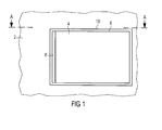
- Fig. 1 shows a side view of a preferred embodiment, namely the Cargo door according to the present invention.
- the reference numeral 2 in Fig. 1 denotes the Shell of the aircraft fuselage.
- the reference numeral 4 denotes that in the opening 6 in the Shell 2 arranged cargo gate.
- the cargo door is in the closed position.
- the Reference numeral 8 in Fig. 1 denotes a first locking element, which also with Closure is designated.
- the opening 6 in the shell 2 is through a gate frame 10, in the example, locking bushes are arranged defined. Instead of It is locking sleeves in the door frame 10 and corresponding pins in the gate 4 also possible to design pins in the frame and bushes on the gate.
- the cargo door 4 has a smaller extent than the opening 6 on.
- the first closure element 8 is provided which just the gap between the opening 6 and the cargo door 4 closes.
- that's the first one Closure element 8 the dimensions of the gap between the cargo door 4 and the opening. 6 customized.
- the door frame 10 the first closure element 8 and the cargo door 4 are so in the shell 2 of the fuselage fitted that achieves a nearly seamless surface becomes. This allows avoiding turbulences of the passing air.
- Fig. 1 a Section view defined.
- Figs. 2a to 2d are different opening stages of Cargo gates 4 along this section line A-A shown.
- FIGS. 2a to 2d show various opening stages of the cargo door 4 in a sectional view along the section line A-A.
- Fig. 2a shows the cargo door 4 in the locked state.
- Fig. 2a is the gap between the shell 2 and the cargo door 4 is closed by the closure 8.
- Fig. 2a are two second Locking elements 12 are provided. These second locking elements 12 provide a further locking of the cargo tube 4 available.
- the cargo door 4 is supported on the door frame 10.
- FIG. 2a shows the fully closed, locked state of the cargo door 4, for example, during operation of the aircraft, i. during the flight, dar.
- Fig. 2b shows a first opening stage of the cargo door 4.
- the first closure element 8 (closure) from the gap to the inside of the Fuselage offset.
- this may be the first locking element 8 the inside of the cargo door 4 are folded, as shown in Fig. 2b.
- Fig. 2c shows a second opening stage of the cargo door 4, compared to the first Opening stage represents a later opening time.
- the cargo door 4 along a longitudinal direction of the fuselage (the X direction of the Fuselage) so that the second locking clamps 12 are unlocked have been.
- the freedom of movement of the cargo door 4 in the opening was 6 exploited and here through the gap, by means of the first locking element 8 in closed state is provided, is provided.
- a gap width of the gap by means of the first locking element 8 in Closed state is closed, so that enough freedom of movement is made possible for the cargo door 4 to the effect that the second locking elements 12th be unlocked.
- Fig. 2d shows a third opening stage of the cargo door 4.
- the cargo door 4 to the outside of the shell 2 from the opening led out. This is preferably done by means of a movement along a normal to the Shell 2 scored. Then the cargo door 4 along the longitudinal direction of the aircraft, here represented by the arrow 14, so shifted that the opening in the fuselage is released.
- the locking of the cargo door 4 takes place the parallel to the aircraft X-axis (longitudinal axis of the fuselage) move the Cargo gates 4 with the second locking elements 12.
- the second Locking elements 12 may be attached to the cargo door 4, for example Locking pin, which in corresponding, located on the aircraft structure sockets intervention.
- the gate opening be larger than the cargo door 4 itself.
- the result resulting gap now serves as an element of locking by the first Locking element 8 is used to close the gap.
- the gate that after the Lock with the second locking elements 12 still a freedom of movement along the longitudinal direction of the aircraft, is now through the first Locking element 8 firmly clamped in the door opening.
- the cargo door 4 is preferably designed as a sliding gate. Such a sliding door is guided on three gate-side rollers in rails, the for example, can be attached to the aircraft structure. This will be below will be described further.
- Fig. 3a shows a three-dimensional representation of the inside of the cargo door 4.
- Fig. 3b shows a three-dimensional side view of the cargo door of 3a.
- the door-side Locking elements which in corresponding fuselage-side locking elements for Formation of the second locking element engage, are here as a locking pin educated.
- upper locking pin 42 and lower Locking pin 42 is provided.
- guide rollers are also provided at the top and bottom of the Cargo gates 4 with guide rollers.
- an upper guide roller 20 provided and a lower guide roller 24, which are formed in corresponding Guide rails, which are attached to the fuselage (not shown) to intervene.
- the cargo door 4 illustrated in FIGS. 3a and 3b has middle guide rollers 26 which are formed in a corresponding middle guide rail on the fuselage is appropriate to intervene.
- side locking pins 22 may be provided in the corresponding grooves in the door frame 10 in the opening 6 or can engage or engage in the first locking element 8.
- FIG. 4 shows a three-dimensional view showing the opening of the cargo hold of the Plane looks out.
- the cargo door mounts shown in FIG. 4 are in particular configured, a cargo door 4, as shown in Figs. 3a and 3b, to lead or hold. This will be described in more detail below.
- an upper guide rail 30 is provided, a middle one Guide rail 32 and a lower guide rail 34.
- the upper guide rail 30 and the lower guide rail 34 are approximately opposite to the opening in the shell. 2 arranged the fuselage.
- the middle guide rail 32 is in or on the shell 2 arranged so that the cargo door 4 can be held when opening. Especially is guided through the middle guide rail 32, the cargo door in the open position, in the perspective shown the cargo door in Fig. 4 has been moved outward to the right is.
- Embodiments of the middle guide rail 32 will be discussed below Referring to Figs. 6 to 8 will be described in more detail.
- the upper guide rail 30, the middle guide rail 32 and the lower guide rail 34 are arranged substantially parallel to each other and substantially parallel to the aircraft's longitudinal axis, that is to the X-axis of the Aircraft. As a result, the guidance and displacement of the freighter 4 along the longitudinal axis of the aircraft.
- lateral locking sockets 36 are provided, for example, with the lateral Locking pin 22 (Fig. 3a) of the cargo door 4 cooperate.
- This can be a seat of the cargo door in the goal frame 10 are specified and fixed.
- lower locking sockets 38 and upper locking sockets 40th provided with the upper and lower locking pin (Fig. 3a) of the cargo door. 4 cooperate to form the second locking elements 12.
- Fig. 5 shows a three-dimensional view showing the arrangement and the structure of the upper Locking bushes 40 and the upper locking rail 30 in more detail shows.
- the upper locking bushes 40 can be configured to engage with holes 50 provided in equidistant vertical struts see.
- the holes 50 are preferably arranged in alignment so that the upper Locking pin 42 of the cargo door 4 (Fig. 3a) by means of a movement along the Longitudinal direction of the aircraft are lockable.
- Fig. 6 shows a three-dimensional view on the outside of the shell 2 of the Aircraft fuselage with the middle guide rail.
- the middle guide rail 6 an area on the inside, that is to the Aircraft inside is bent and protrudes into the opening 6.
- the middle Guide rollers (Fig. 3a) of the cargo door 4 engaged when the cargo door completely is locked (that is, the first and second locking elements are locked).
- the cargo door 4 with this inwardly facing portion of the guide rail 32 in Intervention as long as the cargo door 4 moves in the plane of the shell 2. In particular, this is the case when the second locking elements 12 are unlocked.
- FIGS. 7 and 8 are sectional views of preferred embodiments of FIGS middle guide rail 32.
- the guide rail 32 on the shell 2 is arranged by means of a reinforcing element 58.
- the Guide rail 32 in the embodiment of Fig. 8 in the shell 2 by means of a embedded other reinforcing element 60.
- the embodiment of Fig. 8 can it may be necessary that structural changes of the shell in the area of the middle Guide rail 32 are required.
- FIG. 9 shows a three-dimensional detail view of the lower guide rail 34.
- the lower guide rail 2 is substantially parallel to the lower Edge of the opening 6 is provided.
- the lower locking bushes 38 are substantially functionally arranged equal to the upper locking bushes 40.
- the lower guide rail 34 and the upper guide rail 30 and the middle Guide rail 32 arranged such that it is a parallel guide of the cargo door 4 to Make available so that the cargo door is linearly guided.
- FIGS. 10 a to 10 d show three-dimensional views of opening stages of the cargo door 4 according to an embodiment of the present invention.
- Fig. 10a shows the completely locked state, in which both the first locking element 8 and the second locking elements 12 (consisting of pin 42 and upper Locking bushings 40) are locked.
- Fig. 10d is the first locking element 8 completely returned, so that the cargo door 4 along the Longitudinal axis of the aircraft could be offset to the second locking elements Unlock.
- FIGS. 10a shows the completely locked state, in which both the first locking element 8 and the second locking elements 12 (consisting of pin 42 and upper Locking bushings 40) are locked.
- Fig. 10d is the first locking element 8 completely returned, so that the cargo door 4 along the Longitudinal axis of the aircraft could be offset to the second locking elements Unlock.
- the first locking element 8 becomes pulled out of the gap, so that the cargo door 4 within the opening 6 a Freedom of movement has such that there is a left movement along the longitudinal axis of the Plane can then, which then unlocks the second locking elements 12 can be.
- FIGS. 11a to 11d show the unlocking states illustrated in FIGS. 10a to 10d from a different perspective.
- the first becomes Locking element 8 taken to the inside of the fuselage out of the gap.
- the locking member 8 as shown in FIG. 11d, behind the cargo door 4th offset, as was already apparent from Fig. 2b.
- FIG. 12a shows a three-dimensional view showing the locked second Locking elements shows.
- FIG. 12b shows a detail view of FIG. 12a.
- FIGS. 12a and 12b show a state in which the second locking elements are locked, i. of the Locking pin 42 is fully inserted in the upper locking sockets.
- the FIGS. 13a and 13b show views corresponding to FIGS. 12a and 12b, but in FIGS. 13a and 13b, the second locking element is unlocked, i. in particular Fig. 13b to 2, the upper locking pin 42 is out of the locking sleeve 40 led out.
- FIGS. 14 a to 14 c show three-dimensional detail views of the upper guide rail 30 the upper locking bushes 40 and the arrangement of the freighter 4 in the shell. 2
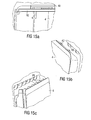
- FIGS. 14a to 14c the cargo door in these figures is in one State in which the second locking elements are completely unlocked and the Freight gate now, as shown in the corresponding views of FIGS. 15a to 15c, after can be offset externally, then laterally pushed along the fuselage can.
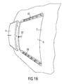
- Fig. 16 shows a three-dimensional view of the outside of the fuselage at completely open cargo door 4.
- Fig. 16 is preferably the Cargo door 4 so far on the outside of the fuselage under the guidance at least slidable by the middle guide rail 32 that the entire opening 6 in the Aircraft fuselage is freely accessible.
- Fig. 17 shows another three-dimensional view illustrating the opened cargo door 4.
- the invention described above allows a simple Locking mechanism that manages with few moving parts. This makes possible almost no maintenance of the cargo door and also a low weight. Also this reduces a susceptibility to error of the locking mechanism.
- a Structural weight reduction of the cargo door can be achieved, for example, at a Compared to today's Airbus A300 / 600 freight gate Total weight advantage of about 430 kg can result.
Landscapes
- Engineering & Computer Science (AREA)
- Mechanical Engineering (AREA)
- Aviation & Aerospace Engineering (AREA)
- Wing Frames And Configurations (AREA)
- Power-Operated Mechanisms For Wings (AREA)
- Lock And Its Accessories (AREA)
- Lubricants (AREA)
- Manufacture Of Macromolecular Shaped Articles (AREA)
- Emergency Lowering Means (AREA)
- Specific Sealing Or Ventilating Devices For Doors And Windows (AREA)
Abstract
Description
- Fig. 1
- zeigt eine Seitenansicht eines Ausführungsbeispiels des Flugzeugtores gemäß der vorliegenden Erfindung in geschlossenem Zustand;
- Fig. 2a bis 2d
- zeigen verschiedene Stadien des Öffnens des Flugzeugtores in Schnittansicht gemäß einem Ausführungsbeispiel der vorliegenden Erfindung;
- Fig. 3a
- zeigt eine dreidimensionale Ansicht der Innenseite des Flugzeugtores gemäß einem Ausführungsbeispiel der vorliegenden Erfindung;
- Fig. 3b
- zeigt eine dreidimensionale Seitenansicht des Flugzeugtores von Fig. 3a;
- Fig. 4
- zeigt eine dreidimensionale Ansicht der Öffnung in der Schale des Flugzeugs vom Rumpfinneren aus;
- Fig. 5
- zeigt Details der Ansicht von Fig. 4;
- Fig. 6
- zeigt ein Ausführungsbeispiel einer mittleren Führungsschiene zur Führung des Flugzeugtors gemäß einem Ausführungsbeispiel der vorliegenden Erfindung;
- Fig. 7
- zeigt eine Schnittansicht der in Fig. 6 dargestellten Führungsschiene;
- Fig. 8
- zeigt ein weiteres Ausführungsbeispiel einer mittleren Führungsschiene in der Schale des Flugzeugs in Schnittansicht;
- Fig. 9
- zeigt eine dreidimensionale Ansicht eines Ausführungsbeispiels einer unteren Führungsschiene gemäß der vorliegenden Erfindung;
- Fig. 10a bis 10d
- zeigen dreidimensionale Ansichten verschiedener Öffnungsstadien des Flugzeugtores gemäß einem Ausführungsbeispiel der vorliegenden Erfindung;
- Fig. 11a bis 11d
- zeigen dreidimensionelle Ansichten der Öffnungsstadien der Fig. 10a bis 10d aus einer anderen perspektivischen Ansicht;
- Fig. 12a
- zeigt eine dreidimensionale Ansicht eines Öffnungsstadiums des Flugzeugtors gemäß einem Ausführungsbeispiel der vorliegenden Erfindung;
- Fig. 12b
- zeigt ein Detail des zweiten Verriegelungsmechanismus in dem Öffnungsstadium, das in Fig. 12a dargestellt ist;
- Fig. 13a
- zeigt eine dreidimensionale Darstellung einer Öffnung des Flugzeugtors gemäß einem Ausführungsbeispiel der vorliegenden Erfindung, wobei das Öffnungsstadium im Vergleich zu der Darstellung von Fig. 12a einem späteren Öffnungszeitpunkt entspricht;
- Fig. 13b
- zeigt eine dreidimensionale Darstellung eines zweiten Verriegelungselementes in dem in Fig. 13a dargestellten Öffnungsstadium;
- Fig. 13a bis 14c
- zeigen dreidimensionale Ansichten von Details eines ersten Öffnungsstadiums;
- Fig. 15a bis 15c
- zeigen den Fig. 14a bis 14c entsprechende Details zu einem zweiten, späteren Öffnungsstadium;
- Fig. 16
- zeigt eine erste zweidimensionale Ansicht, in der das Frachttor in der geöffneten Position angeordnet ist; und
- Fig. 17
- zeigt eine zweite dreidimensionale Ansicht, in der das Frachttor in der geöffneten Position dargestellt ist.
Claims (15)
- Flugzeugtor zum Verschließen einer Öffnung in einer Schale eines Flugzeugs,
wobei das Flugzeugtor entlang im Wesentlichen einer Längsrichtung des Flugzeugs versetzbar ist. - Flugzeugtor nach Anspruch 1,
wobei die Öffnung in der Schale des Flugzeugs größer ist als das Flugzeugtor, so dass bei dem in der Öffnung angeordneten Flugzeugtor zwischen einer ersten Begrenzung des Flugzeugtors und einer zweiten Begrenzung der Öffnung ein Spalt ist. - Flugzeugtor nach Anspruch 2,
wobei ein erstes Verriegelungselement vorgesehen ist, das in dem Spalt zwischen der ersten Begrenzung des Flugzeugtors und der zweiten Begrenzung der Öffnung zur Verriegelung des Flugzeugtors in der Öffnung angeordnet wird. - Flugzeugtor nach Anspruch 3,
wobei zumindest ein zweites Verriegelungselement derart vorgesehen ist, dass das Flugzeugtor mittels einer Versetzung entlang der Längsrichtung des Flugzeugs in der Öffnung verriegelt wird. - Flugzeugtor nach Anspruch 4,
wobei zum Verriegeln des Flugzeugtors zuerst das Flugzeugtor in der Öffnung angeordnet wird, dann das Flugzeugtor in der Öffnung entlang der Längsrichtung des Flugzeugs zur Verriegelung des zumindest einen zweiten Verriegelungselement versetzt wird und dann das erste Verriegelungselement in dem Spalt zwischen der ersten Begrenzung des Flugzeugtors und der zweiten Begrenzung der Öffnung zur Verriegelung angeordnet wird. - Flugzeugtor nach einem der Ansprüche 1 bis 5,
wobei das Flugzeugtor zwischen einem geschlossenen Zustand, in dem das Flugzeugtor in der Öffnung vollständig verriegelt ist, und einem geöffneten Zustand, in dem das Flugzeugtor gegenüber der Öffnung auf einer Außenseite der Schale versetzt ist, so dass ein möglichst großer Bereich der Öffnung frei ist und nicht durch das Flugzeugtor verdeckt ist, versetzbar ist,
wobei zur Führung des Flugzeugtors zwischen dem geschlossenen Zustand und dem geöffneten Zustand zumindest eine Führungsschiene an der Schale angeordnet ist, in die Haltelemente, die an dem Flugzeugtor angeordnet sind, eingreifen. - Flugzeugtor nach Anspruch 6,
wobei die zumindest eine Führungsschiene und die Halteelemente derart zusammenwirken, dass eine Führung des Flugzeugtors entlang der Längsrichtung des Flugzeugs und entlang der Schwerkraft sichergestellt ist. - Flugzeugtor nach Anspruch 7,
wobei die zumindest eine Führungsschiene eine Führung des Flugzeugtors derart ermöglicht, dass das Flugzeugtor von dem geschlossenen Zustand zum Entriegeln zuerst entlang der Längsachse des Flugzeugs um einen ersten Betrag versetzbar ist, zum Herausführen des Flugzeugtors entlang einer Normalen auf der Schale um einen zweiten Betrag versetzbar ist, und zum Freigeben der Öffnung zum geöffneten Zustand hin auf der Außenseite der Schale entlang der Längsachse des Flugzeugs um einen dritten Betrag versetzbar ist,
wobei das Flugzeugtor im Wesentlichen keine Drehbewegung ausführt. - Verfahren zum Öffnen und Verschließen einer Öffnung in einer Schale eines Flugzeugs, umfassend den Schritt:Versetzen des Flugzeugtors entlang im Wesentlichen einer Längsrichtung des Flugzeugs.
- Verfahren nach Anspruch 9,
wobei die Öffnung in der Schale des Flugzeugs größer ist als das Flugzeugtor, so dass bei dem in der Öffnung angeordneten Flugzeugtor zwischen einer ersten Begrenzung des Flugzeugtors und einer zweiten Begrenzung der Öffnung ein Spalt ist. - Verfahren nach Anspruch 10,
wobei zum Verriegelung des Flugzeugtors in der Öffnung ein erstes Verriegelungselement in dem Spalt zwischen der ersten Begrenzung des Flugzeugtors und der zweiten Begrenzung der Öffnung angeordnet wird. - Verfahren nach Anspruch 11,
wobei zum Verriegelung des Flugzeugtors in der Öffnung zumindest ein zweites Verriegelungselement derart entlang der Längsrichtung des Flugzeugs versetzt wird, dass das Flugzeugtor in der Öffnung verriegelt wird. - Verfahren nach Anspruch 12,
wobei zum Verriegeln des Flugzeugtors zuerst das Flugzeugtor in der Öffnung angeordnet wird, dann das Flugzeugtor in der Öffnung entlag der Längsrichtung des Flugzeugs zur Verriegelung des zumindest einer zweiten Verriegelungselement versetzt wird, und dann das erste Verriegelungselement in dem Spalt zwischen der ersten Begrenzung des Flugzeugtors und der zweiten Begrenzung der Öffnung zur Verriegelung angeordnet wird. - Verfahren nach einem der Ansprüche 9 bis 13,
wobei das Flugzeugtor zwischen einem geschlossenen Zustand, in dem das Flugzeugtor in der Öffnung vollständig verriegelt ist, und einem geöffneten Zustand, in dem das Flugzeugtor gegenüber der Öffnung auf einer Außenseite der Schale versetzt wird, so dass ein möglichst großer Bereich der Öffnung frei ist und nicht durch das Flugzeugtor verdeckt ist,
wobei das Flugzeugtor entlang der Längsrichtung des Flugzeugs und entlang der Schwerkraft gehaltert ist. - Verfahren nach Anspruch 14,
wobei das Flugzeugtor von dem geschlossenen Zustand zum Entriegeln zuerst entlang der Längsachse des Flugzeugs um einen ersten Betrag versetzt wird, zum Herausführen des Flugzeugtors entlang einer Normalen auf der Schale um einen zweiten Betrag versetzt wird, und zum Freigeben der Öffnung zum geöffneten Zustand hin auf der Außenseite der Schale entlang der Längsachse des Flugzeugs um einen dritten Betrag versetzt wird,
wobei das Flugzeugtor derart bewegt wird, dass das Flugzeugtor im Wesentlichen keine Drehbewegung ausführt.
Applications Claiming Priority (2)
| Application Number | Priority Date | Filing Date | Title |
|---|---|---|---|
| DE10360484A DE10360484A1 (de) | 2003-12-22 | 2003-12-22 | Flugzeugtor |
| DE10360484 | 2003-12-22 |
Publications (2)
| Publication Number | Publication Date |
|---|---|
| EP1547916A1 true EP1547916A1 (de) | 2005-06-29 |
| EP1547916B1 EP1547916B1 (de) | 2006-10-18 |
Family
ID=34530354
Family Applications (1)
| Application Number | Title | Priority Date | Filing Date |
|---|---|---|---|
| EP04028576A Expired - Lifetime EP1547916B1 (de) | 2003-12-22 | 2004-12-02 | Schiebetor für ein Flugzeug |
Country Status (6)
| Country | Link |
|---|---|
| US (1) | US7290736B2 (de) |
| EP (1) | EP1547916B1 (de) |
| JP (1) | JP4876234B2 (de) |
| AT (1) | ATE342838T1 (de) |
| DE (2) | DE10360484A1 (de) |
| ES (1) | ES2275169T3 (de) |
Families Citing this family (16)
| Publication number | Priority date | Publication date | Assignee | Title |
|---|---|---|---|---|
| US6877695B2 (en) * | 2002-12-13 | 2005-04-12 | The Boeing Company | Hinge cover integration into door seal edges |
| US7744035B2 (en) * | 2005-06-10 | 2010-06-29 | Airbus | Door for compartment of the baggage-compartment type |
| US20070102581A1 (en) * | 2005-06-22 | 2007-05-10 | Wagner William J | System and method for converting a passenger aircraft to a cargo aircraft |
| DE102006016755B3 (de) * | 2006-04-10 | 2007-11-29 | Airbus Deutschland Gmbh | Flugzeugtür mit Überbreite |
| FR2901244B1 (fr) * | 2006-05-16 | 2009-01-09 | Airbus France Sas | Dispositif d'articulation de portes d'une nacelle d'aeronef et nacelle equipee dudit dispositif d'articulation |
| DE102006056441B4 (de) * | 2006-11-28 | 2010-06-02 | Eurocopter Deutschland Gmbh | Verriegelungsvorrichtung für Schiebetüren von Hubschraubern |
| US8523110B2 (en) * | 2007-03-28 | 2013-09-03 | Airbus Operations Gmbh | Door frame component of cast titanium and structural fuselage part |
| JP5135110B2 (ja) | 2008-08-01 | 2013-01-30 | ホンダ・パテンツ・アンド・テクノロジーズ・ノース・アメリカ・エルエルシー | 航空機のスライドドア装置 |
| DE102009016769B4 (de) * | 2009-04-07 | 2015-10-29 | Airbus Operations Gmbh | Rumpfbugtor |
| US9567059B2 (en) | 2015-05-07 | 2017-02-14 | Georgian Aerospace, LLC | Externally mounted auxiliary door for an aircraft |
| EP3165446B1 (de) * | 2015-11-09 | 2018-09-26 | Airbus Operations GmbH | Flugzeugtüranordnung |
| EP3168138B1 (de) * | 2015-11-10 | 2018-06-06 | Airbus Operations GmbH | Flugzeugtüranordnung |
| FR3046133B1 (fr) * | 2015-12-23 | 2019-06-07 | Airbus Operations | Cellule d'aeronef comprenant une porte s'ouvrant en translation rectiligne |
| US10533356B2 (en) * | 2017-01-09 | 2020-01-14 | Textron Innovations Inc. | Latch system with position hold |
| US10882598B2 (en) * | 2018-04-12 | 2021-01-05 | Bell Textron Inc. | Pressurized sliding door |
| RU2757608C1 (ru) * | 2020-12-30 | 2021-10-19 | Акционерное общество "Национальный центр вертолетостроения им. М.Л. Миля и Н.И. Камова" (АО "НЦВ Миль и Камов") | Распашная дверь с телескопическим подкосом открытого положения |
Citations (5)
| Publication number | Priority date | Publication date | Assignee | Title |
|---|---|---|---|---|
| US2445131A (en) * | 1944-08-10 | 1948-07-13 | Yale & Towne Mfg Co | Door mounting |
| GB624831A (en) * | 1947-07-10 | 1949-06-16 | Jack Britt | Improvements in or relating to inspection doors |
| GB1228969A (de) * | 1968-08-05 | 1971-04-21 | ||
| US5303508A (en) * | 1991-03-12 | 1994-04-19 | Aerospatiale Societe Nationale Industrielle | Access door, especially for an aircraft engine cowling, provided with synchronized pivoting articulated flap |
| US6189833B1 (en) * | 1998-09-29 | 2001-02-20 | Sikorsky Aircraft Corporation | Aircraft sliding door system |
Family Cites Families (4)
| Publication number | Priority date | Publication date | Assignee | Title |
|---|---|---|---|---|
| DE1218290B (de) * | 1963-12-21 | 1966-06-02 | Boelkow Gmbh | Schiebetuer fuer Fahrzeuge, insbesondere Luftfahrzeuge |
| US5181677A (en) * | 1991-09-26 | 1993-01-26 | Kaplan Abraham M | Sliding aircraft door |
| US5259576A (en) * | 1992-05-18 | 1993-11-09 | Howard D U | External sliding aircraft door |
| US6487819B1 (en) * | 2000-07-18 | 2002-12-03 | Meritor Light Vehicle Technology L.L.C | Magnetic weather strip |
-
2003
- 2003-12-22 DE DE10360484A patent/DE10360484A1/de not_active Withdrawn
-
2004
- 2004-12-02 ES ES04028576T patent/ES2275169T3/es not_active Expired - Lifetime
- 2004-12-02 AT AT04028576T patent/ATE342838T1/de not_active IP Right Cessation
- 2004-12-02 DE DE502004001789T patent/DE502004001789D1/de not_active Expired - Lifetime
- 2004-12-02 EP EP04028576A patent/EP1547916B1/de not_active Expired - Lifetime
- 2004-12-20 JP JP2004368297A patent/JP4876234B2/ja not_active Expired - Fee Related
- 2004-12-21 US US11/018,640 patent/US7290736B2/en not_active Expired - Fee Related
Patent Citations (5)
| Publication number | Priority date | Publication date | Assignee | Title |
|---|---|---|---|---|
| US2445131A (en) * | 1944-08-10 | 1948-07-13 | Yale & Towne Mfg Co | Door mounting |
| GB624831A (en) * | 1947-07-10 | 1949-06-16 | Jack Britt | Improvements in or relating to inspection doors |
| GB1228969A (de) * | 1968-08-05 | 1971-04-21 | ||
| US5303508A (en) * | 1991-03-12 | 1994-04-19 | Aerospatiale Societe Nationale Industrielle | Access door, especially for an aircraft engine cowling, provided with synchronized pivoting articulated flap |
| US6189833B1 (en) * | 1998-09-29 | 2001-02-20 | Sikorsky Aircraft Corporation | Aircraft sliding door system |
Also Published As
| Publication number | Publication date |
|---|---|
| DE502004001789D1 (de) | 2006-11-30 |
| US7290736B2 (en) | 2007-11-06 |
| JP4876234B2 (ja) | 2012-02-15 |
| EP1547916B1 (de) | 2006-10-18 |
| DE10360484A1 (de) | 2005-07-28 |
| ATE342838T1 (de) | 2006-11-15 |
| US20050133667A1 (en) | 2005-06-23 |
| ES2275169T3 (es) | 2007-06-01 |
| JP2005178770A (ja) | 2005-07-07 |
Similar Documents
| Publication | Publication Date | Title |
|---|---|---|
| DE102018204489B4 (de) | Wagentür eines fahrzeugs, die unabhängig von einer reihenfolge öffenbar und schliessbar ist | |
| EP0196488B1 (de) | Schwenkschiebetür für Fahrzeuge, insbesondere Schienenfahrzeuge, zur Personenbeförderung | |
| EP1547916B1 (de) | Schiebetor für ein Flugzeug | |
| EP0085851B1 (de) | Kraftfahrzeug mit einer Heckklappe | |
| DE60218365T2 (de) | Gelenkvorrichtung für ein Flugzeugtürblatt und Flugzeugtür mit einer solchen Vorrichtung | |
| DE3112681C2 (de) | Trennbares Scharnier, insbesondere für den Anschluß von Karosserieklappen an Karosserien von Kraftfahrzeugen | |
| DE60010606T2 (de) | Verschluss | |
| DE60216181T2 (de) | Schnelle Evakuationseinheit für ein Luftfahrzeug | |
| DE112007001067T5 (de) | Druck/Druck-Schloss | |
| DE2825694A1 (de) | Abwurfgelenk und damit ausgeruestete abwerfbare fahrzeugtuer | |
| DE102007002700A1 (de) | Kraftfahrzeug mit einer eine Türöffnung verschließenden Fahrzeugtür | |
| AT500017A1 (de) | Schwenkschiebetür für fahrzeuge | |
| EP1561620B1 (de) | Mechanismus für ein Schiebedach | |
| DE102010027136B4 (de) | Vorrichtung zum Durchführen einer Öffnungsbewegung einer Tür | |
| DE102004033759A1 (de) | Schiebetürsystem | |
| EP2096027B1 (de) | Klappensteuerung | |
| DE60315253T2 (de) | Kofferraumdeckel für ein cabriofahrzeug mit faltverdeck | |
| DE2419995C3 (de) | Verriegelungsvorrichtung für eine Stockwerkstür eines Fahrstuhlschachtes | |
| DE102016212380B3 (de) | Kabine mit Drehtür | |
| DE102018113991A1 (de) | Anordnung für einen Deckel eines Fahrzeugdachs sowie Fahrzeugdach für ein Kraftfahrzeug | |
| DE69404212T2 (de) | Klappe zum Schliessen einer Öffnung im unteren Teil eines Wagenkastens | |
| DE102005061127A1 (de) | Luftfahrzeugtür-Anordnung sowie Luftfahrzeugrumpf mit einer derartigen Luftfahrzeugtür-Anordnung | |
| EP3287579B1 (de) | Verschlussvorrichtung für eine tür | |
| EP0253263B1 (de) | Fahrzeug mit einem kastenförmigen Aufbau und einer Hubmechanik | |
| DE3209408C2 (de) | Auflageeinrichtung für Schriftgut an einem Verkleidungsrahmen eines Schiebefensters |
Legal Events
| Date | Code | Title | Description |
|---|---|---|---|
| REG | Reference to a national code |
Ref country code: SE Ref legal event code: TRGR |
|
| PUAI | Public reference made under article 153(3) epc to a published international application that has entered the european phase |
Free format text: ORIGINAL CODE: 0009012 |
|
| AK | Designated contracting states |
Kind code of ref document: A1 Designated state(s): AT BE BG CH CY CZ DE DK EE ES FI FR GB GR HU IE IS IT LI LT LU MC NL PL PT RO SE SI SK TR |
|
| AX | Request for extension of the european patent |
Extension state: AL BA HR LV MK YU |
|
| 17P | Request for examination filed |
Effective date: 20051110 |
|
| AKX | Designation fees paid |
Designated state(s): AT BE BG CH CY CZ DE DK EE ES FI FR GB GR HU IE IS IT LI LT LU MC NL PL PT RO SE SI SK TR |
|
| GRAP | Despatch of communication of intention to grant a patent |
Free format text: ORIGINAL CODE: EPIDOSNIGR1 |
|
| GRAS | Grant fee paid |
Free format text: ORIGINAL CODE: EPIDOSNIGR3 |
|
| GRAA | (expected) grant |
Free format text: ORIGINAL CODE: 0009210 |
|
| AK | Designated contracting states |
Kind code of ref document: B1 Designated state(s): AT BE BG CH CY CZ DE DK EE ES FI FR GB GR HU IE IS IT LI LT LU MC NL PL PT RO SE SI SK TR |
|
| PG25 | Lapsed in a contracting state [announced via postgrant information from national office to epo] |
Ref country code: RO Free format text: LAPSE BECAUSE OF FAILURE TO SUBMIT A TRANSLATION OF THE DESCRIPTION OR TO PAY THE FEE WITHIN THE PRESCRIBED TIME-LIMIT Effective date: 20061018 Ref country code: IE Free format text: LAPSE BECAUSE OF FAILURE TO SUBMIT A TRANSLATION OF THE DESCRIPTION OR TO PAY THE FEE WITHIN THE PRESCRIBED TIME-LIMIT Effective date: 20061018 Ref country code: LT Free format text: LAPSE BECAUSE OF FAILURE TO SUBMIT A TRANSLATION OF THE DESCRIPTION OR TO PAY THE FEE WITHIN THE PRESCRIBED TIME-LIMIT Effective date: 20061018 Ref country code: SK Free format text: LAPSE BECAUSE OF FAILURE TO SUBMIT A TRANSLATION OF THE DESCRIPTION OR TO PAY THE FEE WITHIN THE PRESCRIBED TIME-LIMIT Effective date: 20061018 Ref country code: PL Free format text: LAPSE BECAUSE OF FAILURE TO SUBMIT A TRANSLATION OF THE DESCRIPTION OR TO PAY THE FEE WITHIN THE PRESCRIBED TIME-LIMIT Effective date: 20061018 Ref country code: NL Free format text: LAPSE BECAUSE OF FAILURE TO SUBMIT A TRANSLATION OF THE DESCRIPTION OR TO PAY THE FEE WITHIN THE PRESCRIBED TIME-LIMIT Effective date: 20061018 Ref country code: SI Free format text: LAPSE BECAUSE OF FAILURE TO SUBMIT A TRANSLATION OF THE DESCRIPTION OR TO PAY THE FEE WITHIN THE PRESCRIBED TIME-LIMIT Effective date: 20061018 Ref country code: FI Free format text: LAPSE BECAUSE OF FAILURE TO SUBMIT A TRANSLATION OF THE DESCRIPTION OR TO PAY THE FEE WITHIN THE PRESCRIBED TIME-LIMIT Effective date: 20061018 Ref country code: CZ Free format text: LAPSE BECAUSE OF FAILURE TO SUBMIT A TRANSLATION OF THE DESCRIPTION OR TO PAY THE FEE WITHIN THE PRESCRIBED TIME-LIMIT Effective date: 20061018 |
|
| REG | Reference to a national code |
Ref country code: GB Ref legal event code: FG4D Free format text: NOT ENGLISH |
|
| REG | Reference to a national code |
Ref country code: CH Ref legal event code: EP Ref country code: IE Ref legal event code: FG4D Free format text: LANGUAGE OF EP DOCUMENT: GERMAN |
|
| REF | Corresponds to: |
Ref document number: 502004001789 Country of ref document: DE Date of ref document: 20061130 Kind code of ref document: P |
|
| PG25 | Lapsed in a contracting state [announced via postgrant information from national office to epo] |
Ref country code: MC Free format text: LAPSE BECAUSE OF NON-PAYMENT OF DUE FEES Effective date: 20061231 Ref country code: BE Free format text: LAPSE BECAUSE OF NON-PAYMENT OF DUE FEES Effective date: 20061231 |
|
| PG25 | Lapsed in a contracting state [announced via postgrant information from national office to epo] |
Ref country code: DK Free format text: LAPSE BECAUSE OF FAILURE TO SUBMIT A TRANSLATION OF THE DESCRIPTION OR TO PAY THE FEE WITHIN THE PRESCRIBED TIME-LIMIT Effective date: 20070118 Ref country code: BG Free format text: LAPSE BECAUSE OF FAILURE TO SUBMIT A TRANSLATION OF THE DESCRIPTION OR TO PAY THE FEE WITHIN THE PRESCRIBED TIME-LIMIT Effective date: 20070118 |
|
| PG25 | Lapsed in a contracting state [announced via postgrant information from national office to epo] |
Ref country code: IS Free format text: LAPSE BECAUSE OF FAILURE TO SUBMIT A TRANSLATION OF THE DESCRIPTION OR TO PAY THE FEE WITHIN THE PRESCRIBED TIME-LIMIT Effective date: 20070218 |
|
| PG25 | Lapsed in a contracting state [announced via postgrant information from national office to epo] |
Ref country code: PT Free format text: LAPSE BECAUSE OF FAILURE TO SUBMIT A TRANSLATION OF THE DESCRIPTION OR TO PAY THE FEE WITHIN THE PRESCRIBED TIME-LIMIT Effective date: 20070319 |
|
| NLV1 | Nl: lapsed or annulled due to failure to fulfill the requirements of art. 29p and 29m of the patents act | ||
| ET | Fr: translation filed | ||
| REG | Reference to a national code |
Ref country code: ES Ref legal event code: FG2A Ref document number: 2275169 Country of ref document: ES Kind code of ref document: T3 |
|
| REG | Reference to a national code |
Ref country code: IE Ref legal event code: FD4D |
|
| PLBE | No opposition filed within time limit |
Free format text: ORIGINAL CODE: 0009261 |
|
| STAA | Information on the status of an ep patent application or granted ep patent |
Free format text: STATUS: NO OPPOSITION FILED WITHIN TIME LIMIT |
|
| 26N | No opposition filed |
Effective date: 20070719 |
|
| BERE | Be: lapsed |
Owner name: AIRBUS DEUTSCHLAND G.M.B.H. Effective date: 20061231 |
|
| PG25 | Lapsed in a contracting state [announced via postgrant information from national office to epo] |
Ref country code: AT Free format text: LAPSE BECAUSE OF NON-PAYMENT OF DUE FEES Effective date: 20061202 |
|
| PG25 | Lapsed in a contracting state [announced via postgrant information from national office to epo] |
Ref country code: GR Free format text: LAPSE BECAUSE OF FAILURE TO SUBMIT A TRANSLATION OF THE DESCRIPTION OR TO PAY THE FEE WITHIN THE PRESCRIBED TIME-LIMIT Effective date: 20070119 |
|
| PG25 | Lapsed in a contracting state [announced via postgrant information from national office to epo] |
Ref country code: EE Free format text: LAPSE BECAUSE OF FAILURE TO SUBMIT A TRANSLATION OF THE DESCRIPTION OR TO PAY THE FEE WITHIN THE PRESCRIBED TIME-LIMIT Effective date: 20061018 |
|
| PG25 | Lapsed in a contracting state [announced via postgrant information from national office to epo] |
Ref country code: LU Free format text: LAPSE BECAUSE OF NON-PAYMENT OF DUE FEES Effective date: 20061202 Ref country code: TR Free format text: LAPSE BECAUSE OF FAILURE TO SUBMIT A TRANSLATION OF THE DESCRIPTION OR TO PAY THE FEE WITHIN THE PRESCRIBED TIME-LIMIT Effective date: 20061018 Ref country code: HU Free format text: LAPSE BECAUSE OF FAILURE TO SUBMIT A TRANSLATION OF THE DESCRIPTION OR TO PAY THE FEE WITHIN THE PRESCRIBED TIME-LIMIT Effective date: 20070419 |
|
| PG25 | Lapsed in a contracting state [announced via postgrant information from national office to epo] |
Ref country code: CY Free format text: LAPSE BECAUSE OF FAILURE TO SUBMIT A TRANSLATION OF THE DESCRIPTION OR TO PAY THE FEE WITHIN THE PRESCRIBED TIME-LIMIT Effective date: 20061018 |
|
| REG | Reference to a national code |
Ref country code: CH Ref legal event code: PL |
|
| PG25 | Lapsed in a contracting state [announced via postgrant information from national office to epo] |
Ref country code: CH Free format text: LAPSE BECAUSE OF NON-PAYMENT OF DUE FEES Effective date: 20081231 Ref country code: LI Free format text: LAPSE BECAUSE OF NON-PAYMENT OF DUE FEES Effective date: 20081231 |
|
| REG | Reference to a national code |
Ref country code: ES Ref legal event code: PC2A Owner name: AIRBUS OPERATIONS GMBH Effective date: 20110930 |
|
| REG | Reference to a national code |
Ref country code: FR Ref legal event code: CD Owner name: AIRBUS OPERATIONS GMBH Effective date: 20111118 |
|
| REG | Reference to a national code |
Ref country code: FR Ref legal event code: PLFP Year of fee payment: 12 |
|
| REG | Reference to a national code |
Ref country code: DE Ref legal event code: R082 Ref document number: 502004001789 Country of ref document: DE Representative=s name: LKGLOBAL | LORENZ & KOPF PARTG MBB PATENTANWAE, DE Ref country code: DE Ref legal event code: R082 Ref document number: 502004001789 Country of ref document: DE Representative=s name: KOPF WESTENBERGER WACHENHAUSEN PATENTANWAELTE , DE |
|
| REG | Reference to a national code |
Ref country code: FR Ref legal event code: PLFP Year of fee payment: 13 |
|
| PGFP | Annual fee paid to national office [announced via postgrant information from national office to epo] |
Ref country code: GB Payment date: 20161222 Year of fee payment: 13 Ref country code: DE Payment date: 20161213 Year of fee payment: 13 |
|
| PGFP | Annual fee paid to national office [announced via postgrant information from national office to epo] |
Ref country code: SE Payment date: 20161221 Year of fee payment: 13 Ref country code: ES Payment date: 20161213 Year of fee payment: 13 Ref country code: FR Payment date: 20161222 Year of fee payment: 13 |
|
| PGFP | Annual fee paid to national office [announced via postgrant information from national office to epo] |
Ref country code: IT Payment date: 20161223 Year of fee payment: 13 |
|
| REG | Reference to a national code |
Ref country code: DE Ref legal event code: R119 Ref document number: 502004001789 Country of ref document: DE |
|
| GBPC | Gb: european patent ceased through non-payment of renewal fee |
Effective date: 20171202 |
|
| PG25 | Lapsed in a contracting state [announced via postgrant information from national office to epo] |
Ref country code: SE Free format text: LAPSE BECAUSE OF NON-PAYMENT OF DUE FEES Effective date: 20171203 |
|
| REG | Reference to a national code |
Ref country code: FR Ref legal event code: ST Effective date: 20180831 |
|
| PG25 | Lapsed in a contracting state [announced via postgrant information from national office to epo] |
Ref country code: IT Free format text: LAPSE BECAUSE OF NON-PAYMENT OF DUE FEES Effective date: 20171202 Ref country code: DE Free format text: LAPSE BECAUSE OF NON-PAYMENT OF DUE FEES Effective date: 20180703 Ref country code: FR Free format text: LAPSE BECAUSE OF NON-PAYMENT OF DUE FEES Effective date: 20180102 |
|
| PG25 | Lapsed in a contracting state [announced via postgrant information from national office to epo] |
Ref country code: GB Free format text: LAPSE BECAUSE OF NON-PAYMENT OF DUE FEES Effective date: 20171202 |
|
| REG | Reference to a national code |
Ref country code: ES Ref legal event code: FD2A Effective date: 20190702 |
|
| PG25 | Lapsed in a contracting state [announced via postgrant information from national office to epo] |
Ref country code: ES Free format text: LAPSE BECAUSE OF NON-PAYMENT OF DUE FEES Effective date: 20171203 |