EP1547883A1 - Balai d'essuie-glace pour nettoyer des pare-brise de vehicules - Google Patents
Balai d'essuie-glace pour nettoyer des pare-brise de vehicules Download PDFInfo
- Publication number
- EP1547883A1 EP1547883A1 EP05102152A EP05102152A EP1547883A1 EP 1547883 A1 EP1547883 A1 EP 1547883A1 EP 05102152 A EP05102152 A EP 05102152A EP 05102152 A EP05102152 A EP 05102152A EP 1547883 A1 EP1547883 A1 EP 1547883A1
- Authority
- EP
- European Patent Office
- Prior art keywords
- wiper blade
- wiper
- blade according
- strip
- spring rails
- Prior art date
- Legal status (The legal status is an assumption and is not a legal conclusion. Google has not performed a legal analysis and makes no representation as to the accuracy of the status listed.)
- Granted
Links
Images


Classifications
-
- B—PERFORMING OPERATIONS; TRANSPORTING
- B60—VEHICLES IN GENERAL
- B60S—SERVICING, CLEANING, REPAIRING, SUPPORTING, LIFTING, OR MANOEUVRING OF VEHICLES, NOT OTHERWISE PROVIDED FOR
- B60S1/00—Cleaning of vehicles
- B60S1/02—Cleaning windscreens, windows or optical devices
- B60S1/04—Wipers or the like, e.g. scrapers
- B60S1/32—Wipers or the like, e.g. scrapers characterised by constructional features of wiper blade arms or blades
- B60S1/38—Wiper blades
- B60S1/3848—Flat-type wiper blade, i.e. without harness
- B60S1/3874—Flat-type wiper blade, i.e. without harness with a reinforcing vertebra
- B60S1/3875—Flat-type wiper blade, i.e. without harness with a reinforcing vertebra rectangular section
- B60S1/3879—Flat-type wiper blade, i.e. without harness with a reinforcing vertebra rectangular section placed in side grooves in the squeegee
-
- B—PERFORMING OPERATIONS; TRANSPORTING
- B60—VEHICLES IN GENERAL
- B60S—SERVICING, CLEANING, REPAIRING, SUPPORTING, LIFTING, OR MANOEUVRING OF VEHICLES, NOT OTHERWISE PROVIDED FOR
- B60S1/00—Cleaning of vehicles
- B60S1/02—Cleaning windscreens, windows or optical devices
- B60S1/04—Wipers or the like, e.g. scrapers
- B60S1/32—Wipers or the like, e.g. scrapers characterised by constructional features of wiper blade arms or blades
- B60S1/38—Wiper blades
- B60S1/3848—Flat-type wiper blade, i.e. without harness
-
- B—PERFORMING OPERATIONS; TRANSPORTING
- B60—VEHICLES IN GENERAL
- B60S—SERVICING, CLEANING, REPAIRING, SUPPORTING, LIFTING, OR MANOEUVRING OF VEHICLES, NOT OTHERWISE PROVIDED FOR
- B60S1/00—Cleaning of vehicles
- B60S1/02—Cleaning windscreens, windows or optical devices
- B60S1/04—Wipers or the like, e.g. scrapers
- B60S1/32—Wipers or the like, e.g. scrapers characterised by constructional features of wiper blade arms or blades
- B60S1/38—Wiper blades
- B60S2001/3812—Means of supporting or holding the squeegee or blade rubber
- B60S2001/3817—Means of supporting or holding the squeegee or blade rubber chacterised by a backing strip to aid mounting of squeegee in support
- B60S2001/382—Means of supporting or holding the squeegee or blade rubber chacterised by a backing strip to aid mounting of squeegee in support the backing strip being an essentially planar reinforcing strip, e.g. vertebra
-
- B—PERFORMING OPERATIONS; TRANSPORTING
- B60—VEHICLES IN GENERAL
- B60S—SERVICING, CLEANING, REPAIRING, SUPPORTING, LIFTING, OR MANOEUVRING OF VEHICLES, NOT OTHERWISE PROVIDED FOR
- B60S1/00—Cleaning of vehicles
- B60S1/02—Cleaning windscreens, windows or optical devices
- B60S1/04—Wipers or the like, e.g. scrapers
- B60S1/32—Wipers or the like, e.g. scrapers characterised by constructional features of wiper blade arms or blades
- B60S1/38—Wiper blades
- B60S2001/3812—Means of supporting or holding the squeegee or blade rubber
- B60S2001/3822—Means of supporting or holding the squeegee or blade rubber characterised by additional means to prevent longitudinal sliding of squeegee in support, e.g. clips
Definitions
- wiper blades referred to in the preamble of claim 1 is the type Support element as possible over the entire wiping field swept by the wiper blade uniform distribution of the wiper arm connected to the wiper blade Ensure outgoing wiper blade pressure on the disc.
- the curvature of the wiper blade So it has to be a bit stronger than the one in the wiping field on the window to be wiped measured strongest curvature.
- the support element thus replaces the expensive Mounting bracket construction with two spring rails arranged in the wiper strip, as they are is practiced in conventional wiper blades (DE-OS 15 05 397).
- the invention is based on a wiper blade according to the preamble of claim 1.
- a wiper blade of this type (DE-GM-document 29611722.6) are the two Spring rails in one piece by arranged at its two ends transverse webs connected. Since these transverse webs must be in the plane of the spring rails must between the mutually facing longitudinal edges lying of the spring rails and the crossbars enclosed slot in its one end section can be extended so that a proper mounting of the wiper strip in the slot is possible.
- These Mounting extension may be the spring characteristics of the support element with regard to to adversely affect the desired wiper result. Also, this is manual Threading the wiper strip over this extension in the slot costly.
- the wiper strip from one end of the support element between the two mutually facing longitudinal edges of the spring rail rectilinear introduce, with their inner, free edge strips in the longitudinal grooves of the wiper strip plunge.
- This simple assembly movement can be done without difficulty Automatic assembly machines are carried out, thereby achieving a significant cost reduction becomes.
- the disadvantageous assembly extension of the slot can be omitted, because the bridge-like transverse webs the rectilinear assembly movement of the wiper strip of a Allow end of support element.
- a stable, permanent connection between the spring rails and the transverse webs is achieved by welding these individual components.
- a stable, low-torsion support element is achieved, if at least at each End portion of the two mutually associated spring rails arranged a cross bar is.
- the two To connect spring rails by means of another bridge-like transverse webs together.
- the arrangement of a single crosspiece each end portion of the support member to obtain a stable, torsion-free Wischblatts is sufficient.
- a particularly advantageous embodiment of the wiper blade results when the over their Longitudinal extension of a consistent cross-section having wiper strip on the disc can be applied, strip-like wiper lip, which has a through one another opposite arranged groove-like constrictions formed narrow web bar with one held on the support element cover strip is connected and each of the two adjacent inner longitudinal edges of the spring rails in one of the two groove-like constrictions of the wiper strip is arranged. This reduces the Overall height of the wiper blade considerably. Because the width of the constriction groove in one Part area is wider than the thickness of the spring rails, the wiper lip during the Always tilt the wiping operation into the required towage position.
- the lateral boundary surfaces of the groove-like Constrictions diverge from the web bar to the longitudinal sides of the wiper strip.
- the Spring rails can so with appropriate tuning the wiper strip on the Guide bar and the wiper lip at the same time their necessary tilting movement in the Enable towing position.
- a development of the invention provides that the one lateral boundary surface of the groove-like constrictions seen in cross section has a convex course. Thereby is a cheap and quiet rolling movement of this side wall to her facing band surface of the relevant spring rail allows.
- the wiper lip on a completely closed longitudinal channel.
- connection device for a The wiper blade moving wiper arm unnecessary, protrudes each of the two spring rail at least with a central edge strip from its groove-like constriction, so that the connection device can be attached to the exposed edge strips.
- Figure 1 shows a side view of an inventive Wischblatts
- Figure 2 is a stretched view of the wiper blade according to Figure 1 in drawn to scale in perspective
- Figure 3 is a for according to the invention wiper blade belonging shortened support element in enlarged, elongated, perspective view
- Figure 4 shows the sectional area of a Section along the line IV-IV in Figure 2 in an enlarged view
- Figure 5 is a in Figure 2 designated V detail in an enlarged view
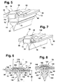
- Figure 6 the Section of a section according to Figure 4 by another embodiment of the according to the invention wiper blade
- Figure 7 a figure 5 corresponding detail of Wischblatts according to Figure 6
- Figure 8 shows the sectional area of a section according to Figures 4 and FIG.
- FIG. 9 a schematic representation of the sectional area of a section along the line IX-IX in Figure 2 by an inventive wiper blade in an enlarged view of this on the 10, the wiper blade according to FIG. 9 is placed on the wiper surface to be wiped during the wiping operation in the one wiping direction and FIG. 11 the wiper blade according to FIG. 9 during the wiping operation in the other wiping direction.
- a wiper blade 10 shown in FIGS. 1 and 2 has a band-like elongated, resilient support element 12, on the underside 13 an elongated, rubber-elastic wiper strip 14 is arranged longitudinal axis parallel.
- the support element 14, which can also be referred to as a spring bar is in its middle section arranged the wiper blade-side part 16 of a connecting device, with the help of the Wiper blade 10 hinged with a dot-dash line indicated in Figure 1, driven Wiper arm 18 can be releasably connected.
- the wiper arm 18 is at his free end provided with the wiper arm side part of the connecting device.
- the surface to be wiped is indicated by a dot-dash line 22 in Figure 1. Because the line 22 is the strongest Curve of the disc surface is to clearly show that the curvature of the with its two ends to the disc fitting, still unloaded wiper blade 10 is stronger than the maximum disc curvature ( Figure 1). Under the pressure (Arrow 20) wipes the wiper blade 10 of its wiper lip 24 over its entire length the disc surface 22 at. This builds in the example made of metal, spring-elastic support member 12 a tension, which is for a proper Plant the wiper strip 14 and the wiper lip 24 over its entire length on the disc as well as for an even distribution of the contact pressure.
- the support member 12 of the Wiper blade 10 with a distance 26 in front of the wiper disk 22 is located. It is whose arrangement is such that its band surfaces 11 and 13 are in a plane which is substantially parallel to be wiped Disc surface 22 extends.
- the particularly advantageous construction of the support element 12 is particularly apparent from Figures 3 and 4. It has two in one common Level lying band-like spring rails 28 and 30, which are aligned parallel to each other are. The mutually facing inner longitudinal edges 32 are located in one Distance 34 from each other.
- each bridge-like crosspiece is with its end portions 40 on the upper side 11 of the support member 12 and at its spring rails 28, 30 at.
- Each of the two transverse webs 36 and 28 has a central portion 42 extending at a distance 44 from the upper band surface 11 of FIG Spring rails is located and thus justified their bridge-like shape. Because the Longitudinal extent 46 of the central portions 42 is greater than the distance 34 between the facing each other inner longitudinal edges 32, the two spring rails extend 28 and 30 with inner edge strips 48 in the region of the central portions 42, wherein the Edge strip 48 at a distance 44 below the middle portions 42nd are arranged.
- the contact force distribution this is also a regulatory, stress-free Ensure guidance of the wiper strip 14 during wiping operation. This is also one silent wiping operation ensured.
- the wiper strip 14 of this first embodiment has a cross section based on the Figure 4 should be made clear. It has a header 50, with which the actual wiping takeover wiper lip 24 via a narrow web bar 52nd connected is. The arrangement of the web bar 52 allows tilting of the wiper lip 24th in a wiping work-promoting towing position, which will be explained later.
- the Header 50 is at their opposite longitudinal sides with them Long sides open edge longitudinal grooves 54 and 56 provided.
- the longitudinal grooves 54 and 56 serve to receive the inner edge strips 48 of the spring rails 28 and 30. Die Depth of the longitudinal grooves 54 and 56 is chosen so that between the two longitudinal grooves Wall 58 remains.
- the header 50 thus has a base bar 60 and a cover strip 62, which are both connected by the wall 58 with each other.
- the thickness 64 of the wall 58 is smaller than the distance 34 between the inner longitudinal edges 32 of the spring rails 28, 30 or smaller than the distance between the inner edge strips 48th
- the width of the two longitudinal grooves 54 and 56 in the header 50 is so on the thickness of Spring rails 28, 30 or their inner edge strips 48 matched that a tension-free mounting of the wiper strip on the support element 12 is ensured if the wiper strip according to FIG. 4 is in contact with the support element 12 according to FIG. 3 assembled.
- the width 66 of the cover strip 62 is slightly smaller than that also as a bridge width to be designated longitudinal extent 46 of the central portion 42 and whose thickness 67 is less than the distance 44 between the central portion 42 and the Upper sides 11 of the spring rails 28, 30 can over their entire longitudinal extent a constant cross-section wiper strip 14 without difficulty in Inserted longitudinally in the support member 12 and connected to this become.
- FIG. 1 Another special feature of the wiper blade according to the invention is shown in FIG.
- the adjacent end face 72 at least partially overlapping Stop 74 is provided.
- the stop 74 is a cranked, flap-like extension of the central portion 42 is formed. If each of the two Wiper blade ends or each of the two support element ends with a Crosspiece 70 is provided according to Figure 5, it should be ensured that the distance between the mutually facing inner walls 75 of the stop tabs 74 is slightly larger Length 76 of the wiper strip 14 ( Figure 2).
- the length 78 of the support member 12 is slightly larger than the length 76th the wiper strip 14.
- the two-sided arrangement of the stops 74 thus forms a effective protection against wandering out of the wiper strip 14 in the longitudinal direction its support member 12 during the wiping operation.
- the bend of at least one of the two stop tabs 74 only after the introduction of the wiper strip 14 made in the support member 12.
- the arranged in the central portion of the wiper blade 10 part 16 of the connecting device for the wiper arm engages the respective outer, from the longitudinal grooves 54 and 56th projecting outer edge strip 80 of the spring rails 28, 30 and the Support member 12.
- the connection between the part 16 and the support member 12 can be positive and / or non-positive.
- With a corresponding length of the wiper blade can it may also be expedient if between the two ends arranged transverse webs 36 and 38 further corresponding transverse webs are arranged.
- a preferably made of plastic cap 82 preferably snapped arranged, preferably latched ( Figures 1 and 2).
- FIGS to 8 Further embodiments of the wiper blade according to the invention are shown in FIGS to 8 shown.
- the support elements of these embodiments completely correspond to the already explained support elements 12 of Figures 3 to 5, so that in these figures for it used reference numbers can be taken directly.
- the design of the Wiper strip 100 in this embodiment differs fundamentally from Structure of the wiper strip 14 in the embodiment already described.
- Figure 6 shows, the wiper strip 100 has only one wiper lip 101, the is integrally connected via a web bar 102 with a cover strip 104.
- the at already described embodiments according to Figures 4 and 5 existing Base bar 60 is thus eliminated.
- the inner edge strips 48 of the spring rails 28 and 30th lie in groove-like constrictions 106 of the wiper strip 100, which to form the narrow web bar 102 are necessary.
- the other lateral boundary surface 110 of the groove-like Constriction 106 is thus directly the lower band surface 13 of the support member 12th across from. It can thus be seen that each of the two inner longitudinal edges 32 of the two spring rails 28, 30 and the support member 12 in one of the two groove-like constrictions 106 of the wiper strip 100 is arranged.
- the two lateral boundary surfaces 110th the constrictions 106 are formed spherical and arranged so that the width dimension the groove-like constrictions 106 is wider at least over an outer portion as the thickness of the spring rails 28, 30.
- the width is 112 the web bar 102 in such a way to the distance 34 between the facing each other inner longitudinal edges 32 of the spring rails 28, 30 tuned that between the Bar strip and the spring rails an air gap remains.
- the thickness here too 114 of the cover strip 104 is slightly less than the distance 44 between the central portion 42 of the transverse web 36 and the inner edge strip 48.
- the width 116 of Cover strip 104 is slightly smaller than the longitudinal extent 46 of the central portion 42 of the bridge-like transverse webs 36.
- the plane lies in which extends the support member 12 at a distance 26 from the surface 22 to wiping disk 22.
- FIG. 8 corresponds in its basic structure of the structure described with reference to FIG 6 Embodiment. Deviating from the embodiment according to FIG. 6, however, are This embodiment, not only the lateral boundary surfaces 110 but also the other, formed on the cover strip 104 lateral boundary surfaces 108 of groove-like constrictions 106 formed spherical. Further different is the Embodiment according to Figure 8 of the embodiment of Figure 6 still by arranged in the wiper lip 101, continuous completely closed Longitudinal channel 118.
- the arrangement of the longitudinal channel 118 in the wiper lip can be alone alone or in conjunction with other longitudinal grooves for a soft, quiet Turnover behavior of the wiper lip during wiping operation provide. It is also his Arrangement not necessarily in connection with the crowned training of Boundary surfaces 108, 110 required.
- each spring rail 28, 30 at least protrudes from its groove-like constriction with a middle, outer edge strip 80, so that at this edge strip 80, the part 16 of the connecting device are attached can.
- the two Spring rails formed as separate components and in the groove-like constrictions the wiper strip can be arranged. Ensuring in particular the Abstand damageses 34 can then be taken over by other, not shown components become.
- FIGS. 9 to 11 show principle sectional views of the wiper blade according to FIG Figures 6 and 7, taken along the line IX-IX in Figure 2 wherein in Figure 9 the Wiper blade 10 with its wiper lip 101 only to be wiped Disc surface 22 is placed.
- the wiper strip 100 is with play between the inner longitudinal edges 32 of the two spring rails 28, 30 held (see also Figures 3 and 4). Since the length 76 of the wiper strip 100 is also slightly smaller than the length 78 of the Support member 12 or less than the dimension between the facing each other Inner walls 75 of the stops 74 at the two ends of the support member 12 results a so-called "free-floating", stress-free but reliable holder of the Wiper strip 100 in the support element 12.
- the wiper blade 10 under load through the Contact pressure (arrow 20 in FIG. 1) in the direction of the arrow 122 in FIG. 10 via the disk 22 is moved, the wiper lip 101 tilts in the area of the web bar 102 in an advantageous Towing position wherein the support member 12 of the disc approaches something (arrow 123).
- the Tilting movement is limited by the fact that the one, lateral boundary surface 110 of a groove-like constriction 106 on the underside 13 of a spring rail 30 is supported.
- the wiper blade 10 has reached its reversal position and by the Wiper arm 18 in the opposite direction (arrow 124 in Fig. 11) is moved, tilts Wiper lip 101 via an apparent from Figure 9 intermediate position in his other Towing position (Fig. 11) with the wiper lip 101 with the lateral Boundary surface 110 of the other groove-like constriction 106 on the bottom 13th the other spring rail 28 is supported.
Landscapes
- Engineering & Computer Science (AREA)
- Mechanical Engineering (AREA)
- Ink Jet (AREA)
- Cleaning In General (AREA)
- Vehicle Cleaning, Maintenance, Repair, Refitting, And Outriggers (AREA)
- Body Structure For Vehicles (AREA)
- Window Of Vehicle (AREA)
- Springs (AREA)
Applications Claiming Priority (3)
| Application Number | Priority Date | Filing Date | Title |
|---|---|---|---|
| DE10025706A DE10025706A1 (de) | 2000-05-25 | 2000-05-25 | Wischblatt zum Reinigen von Fahrzeugscheiben |
| DE10025706 | 2000-05-25 | ||
| EP01940118A EP1289805B1 (fr) | 2000-05-25 | 2001-04-04 | Raclette d'essuie-glace pour le nettoyage de vitres de vehicules |
Related Parent Applications (2)
| Application Number | Title | Priority Date | Filing Date |
|---|---|---|---|
| EP01940118A Division EP1289805B1 (fr) | 2000-05-25 | 2001-04-04 | Raclette d'essuie-glace pour le nettoyage de vitres de vehicules |
| EP01940118.1 Division | 2001-04-04 |
Publications (2)
| Publication Number | Publication Date |
|---|---|
| EP1547883A1 true EP1547883A1 (fr) | 2005-06-29 |
| EP1547883B1 EP1547883B1 (fr) | 2012-02-22 |
Family
ID=7643388
Family Applications (2)
| Application Number | Title | Priority Date | Filing Date |
|---|---|---|---|
| EP01940118A Expired - Lifetime EP1289805B1 (fr) | 2000-05-25 | 2001-04-04 | Raclette d'essuie-glace pour le nettoyage de vitres de vehicules |
| EP05102152A Expired - Lifetime EP1547883B1 (fr) | 2000-05-25 | 2001-04-04 | Balai d'essuie-glace pour nettoyer des pare-brise de vehicules |
Family Applications Before (1)
| Application Number | Title | Priority Date | Filing Date |
|---|---|---|---|
| EP01940118A Expired - Lifetime EP1289805B1 (fr) | 2000-05-25 | 2001-04-04 | Raclette d'essuie-glace pour le nettoyage de vitres de vehicules |
Country Status (12)
| Country | Link |
|---|---|
| US (1) | US6978512B2 (fr) |
| EP (2) | EP1289805B1 (fr) |
| JP (1) | JP4856348B2 (fr) |
| KR (1) | KR100764952B1 (fr) |
| CN (1) | CN1196612C (fr) |
| AU (1) | AU780818B2 (fr) |
| BR (1) | BR0106665B1 (fr) |
| CZ (2) | CZ299276B6 (fr) |
| DE (3) | DE10025706A1 (fr) |
| ES (2) | ES2243507T3 (fr) |
| RU (1) | RU2272724C2 (fr) |
| WO (1) | WO2001089891A1 (fr) |
Cited By (12)
| Publication number | Priority date | Publication date | Assignee | Title |
|---|---|---|---|---|
| WO2008049686A1 (fr) * | 2006-10-27 | 2008-05-02 | Robert Bosch Gmbh | Balai d'essuie-glace |
| US8122560B2 (en) | 2006-08-04 | 2012-02-28 | Dongguan Hongyi Wiper Co., Ltd. | Windshield wiper bridge base assembly |
| US9889822B2 (en) | 2014-03-07 | 2018-02-13 | Pylon Manufacturing Corp. | Windshield wiper connector and assembly |
| US10005431B2 (en) | 2011-04-21 | 2018-06-26 | Pylon Manufacturing Corp. | Vortex damping wiper blade |
| US10077026B2 (en) | 2012-02-24 | 2018-09-18 | Pylon Manufacturing Corp. | Wiper blade |
| US10166951B2 (en) | 2013-03-15 | 2019-01-01 | Pylon Manufacturing Corp. | Windshield wiper connector |
| US10189445B2 (en) | 2012-02-24 | 2019-01-29 | Pylon Manufacturing Corp. | Wiper blade |
| US10457252B2 (en) | 2011-07-28 | 2019-10-29 | Pylon Manufacturing Corp. | Windshield wiper adapter, connector and assembly |
| US10464533B2 (en) | 2011-04-21 | 2019-11-05 | Pylon Manufacturing Corp. | Wiper blade with cover |
| US10597004B2 (en) | 2011-07-29 | 2020-03-24 | Pylon Manufacturing Corporation | Windshield wiper connector |
| US10829092B2 (en) | 2012-09-24 | 2020-11-10 | Pylon Manufacturing Corp. | Wiper blade with modular mounting base |
| US11040705B2 (en) | 2016-05-19 | 2021-06-22 | Pylon Manufacturing Corp. | Windshield wiper connector |
Families Citing this family (36)
| Publication number | Priority date | Publication date | Assignee | Title |
|---|---|---|---|---|
| DE10025710A1 (de) * | 2000-02-23 | 2001-08-30 | Bosch Gmbh Robert | Wischblatt für Scheiben insbesondere von Kraftfahrzeugen |
| DE10033778A1 (de) | 2000-07-12 | 2002-04-18 | Valeo Auto Electric Gmbh | Wischvorrichtung |
| DE50107150D1 (de) * | 2000-10-28 | 2005-09-22 | Bosch Gmbh Robert | Gelenkfreies wischblatt, insbesondere für ein kraftfahrzeug |
| DE10120467A1 (de) * | 2001-04-26 | 2002-10-31 | Bosch Gmbh Robert | Wischblatt zum Reinigen von Scheiben, insbesondere von Kraftfahrzeugen |
| DE10259478A1 (de) * | 2002-12-19 | 2004-07-01 | Robert Bosch Gmbh | Wischvorrichtung für Scheiben von Kraftfahrzeugen |
| DE10341275A1 (de) * | 2003-09-08 | 2005-03-31 | Robert Bosch Gmbh | Wischblatt |
| DE602004007097T3 (de) * | 2004-02-26 | 2014-01-16 | Federal-Mogul S.A. | Scheibenwischervorrichtung |
| DE102004015423A1 (de) * | 2004-03-26 | 2005-10-13 | Robert Bosch Gmbh | Wischblatt |
| DE602005005005T2 (de) * | 2005-01-25 | 2009-02-26 | Federal-Mogul S.A. | Scheibenwischvorrichtung |
| TWM279554U (en) * | 2005-06-20 | 2005-11-01 | Ji-Sheng Jang | Improvement of windshield wiper structure |
| DE602006007443D1 (de) * | 2006-05-08 | 2009-08-06 | Federal Mogul Sa | Scheibenwischervorrichtung |
| US20080028564A1 (en) * | 2006-08-04 | 2008-02-07 | Shu-Lan Ku | Wiper blade support structure |
| US7992248B2 (en) * | 2007-05-22 | 2011-08-09 | Federal-Mogul Corporation | Spoilerless flat wiper blade assembly |
| ES2397097T3 (es) * | 2007-06-26 | 2013-03-04 | Federal-Mogul S.A. | Dispositivo de limpiaparabrisas |
| KR101098004B1 (ko) | 2009-08-26 | 2011-12-22 | 주식회사 캐프 | 차량 와이퍼용 멀티 어댑터 |
| US8552690B2 (en) * | 2009-11-06 | 2013-10-08 | Rally Manufacturing, Inc. | Method and system for automatically detecting a voltage of a battery |
| DE102010028102A1 (de) * | 2010-04-22 | 2011-10-27 | Robert Bosch Gmbh | Wischblatt für einen Scheibenwischer |
| US8495787B2 (en) | 2010-08-03 | 2013-07-30 | Rally Manufacturing, Inc. | Windshield wiper |
| USD706200S1 (en) | 2010-09-22 | 2014-06-03 | Pylon Manufacturing Corporation | Windshield wiper cover |
| US8575895B2 (en) | 2011-03-29 | 2013-11-05 | Rally Manufacturing, Inc. | Method and device for voltage detection and charging of electric battery |
| US8806700B2 (en) | 2011-07-29 | 2014-08-19 | Pylon Manufacturing Corporation | Wiper blade connector |
| MX347284B (es) | 2011-07-29 | 2017-04-21 | Pylon Mfg Corp | Conector de limpiaparabrisas. |
| PL2790979T3 (pl) * | 2011-12-14 | 2020-01-31 | Federal-Mogul Corporation | Urządzenie wycieraczkowe do szyby przedniej pojazdu |
| US10723322B2 (en) | 2012-02-24 | 2020-07-28 | Pylon Manufacturing Corp. | Wiper blade with cover |
| KR101474838B1 (ko) | 2013-07-01 | 2014-12-22 | 주식회사 캐프 | 와이퍼 블레이드 조립체 |
| CN103879382A (zh) * | 2014-02-25 | 2014-06-25 | 厦门福来德汽配有限公司 | 雨刷 |
| KR101565825B1 (ko) * | 2014-03-11 | 2015-11-05 | 케이씨더블류 주식회사 | 플랫 와이퍼 블레이드 및 그 결합방법 |
| FR3023810B1 (fr) * | 2014-07-17 | 2018-01-19 | Valeo Systemes D'essuyage | Balai plat carene d'essuie-glace |
| USD777079S1 (en) | 2014-10-03 | 2017-01-24 | Pylon Manufacturing Corp. | Wiper blade frame |
| USD787308S1 (en) | 2014-10-03 | 2017-05-23 | Pylon Manufacturing Corp. | Wiper blade package |
| WO2017075066A1 (fr) | 2015-10-26 | 2017-05-04 | Pylon Manufacturing Corp. | Balai d'essuie-glace |
| US10661759B2 (en) | 2016-05-19 | 2020-05-26 | Pylon Manufacturing Corporation | Windshield wiper connector |
| US10513246B2 (en) | 2016-05-19 | 2019-12-24 | Pylon Manufacturing Corp. | Windshield wiper connector |
| CN109311450A (zh) | 2016-05-19 | 2019-02-05 | 电缆塔制造有限公司 | 挡风玻璃雨刮器连接器 |
| EP3458315B1 (fr) | 2016-05-19 | 2021-09-08 | Pylon Manufacturing Corp. | Balai d'essuie-glace |
| CN109795452B (zh) * | 2019-03-25 | 2020-08-11 | 厦门富可汽车配件有限公司 | 一种雨刷胶条防脱结构及其雨刷 |
Citations (8)
| Publication number | Priority date | Publication date | Assignee | Title |
|---|---|---|---|---|
| US3626544A (en) * | 1970-09-16 | 1971-12-14 | Roberk Co The | Clip for windshield wiper blade refill |
| US3636583A (en) * | 1970-01-26 | 1972-01-25 | Ian K Rosen | Squeegee blade |
| GB1269993A (en) * | 1969-05-17 | 1972-04-12 | Kenneth Jenkinson Meadows | Improvements in or relating to windscreen wiper blades |
| EP0624133B1 (fr) * | 1992-02-04 | 1995-10-11 | Robert Bosch Gmbh | Ensemble balai d'essuie-glace pour le nettoyage des vitres de vehicules automobiles |
| DE19627115A1 (de) * | 1996-07-05 | 1998-01-08 | Bosch Gmbh Robert | Wischblatt für Scheiben von Kraftfahrzeugen |
| WO1999002383A1 (fr) * | 1997-07-11 | 1999-01-21 | Robert Bosch Gmbh | Raclette d'essuie-glace pour le nettoyage de vitres de vehicules |
| DE19802451A1 (de) * | 1998-01-23 | 1999-07-29 | Bosch Gmbh Robert | Wischblatt für Scheiben von Kraftfahrzeugen mit einem langgestreckten, federelastischen Tragelement |
| GB2336293A (en) * | 1998-04-16 | 1999-10-20 | Trico Products Corp | Wiper blade retaining clip; assembling wiper blades and harnesses |
Family Cites Families (14)
| Publication number | Priority date | Publication date | Assignee | Title |
|---|---|---|---|---|
| US2687544A (en) * | 1950-05-10 | 1954-08-31 | Trico Products Corp | Windshield cleaner |
| DE1028896B (de) * | 1954-06-24 | 1958-04-24 | Avog Elektro Und Feinmechanik | Wischerschiene fuer Scheibenwischer |
| US2983945A (en) * | 1958-03-12 | 1961-05-16 | Anderson Co | Wiper blade assembly |
| US3084372A (en) * | 1959-10-14 | 1963-04-09 | Anderson Co | Windshield wiper assembly |
| US3116507A (en) * | 1960-05-02 | 1964-01-07 | Trico Products Corp | Windshield wiper system |
| DE1505357A1 (de) | 1965-01-23 | 1969-05-29 | Otto Bloetz | Fahrzeug zur Befoerderung von pulverigem Schuettgut |
| US3430285A (en) * | 1968-01-31 | 1969-03-04 | Daco Inc | Holder for windshield wiper blade |
| US3958295A (en) * | 1972-10-03 | 1976-05-25 | Tridon Limited | Backing members for use in windshield wipers |
| CH624349A5 (fr) * | 1978-12-05 | 1981-07-31 | J B Brevets | |
| DE19627114A1 (de) | 1996-07-05 | 1998-01-08 | Bosch Gmbh Robert | Wischblatt für Scheiben von Kraftfahrzeugen |
| DE29611722U1 (de) | 1996-07-05 | 1997-11-06 | Bosch Gmbh Robert | Wischblatt für Scheiben von Kraftfahrzeugen |
| DE19650159A1 (de) * | 1996-12-04 | 1998-06-10 | Teves Gmbh Alfred | Wischblatt zur Reinigen von Scheiben an Fahrzeugen |
| DE19718490A1 (de) * | 1997-05-02 | 1998-11-05 | Bosch Gmbh Robert | Wischblatt für Scheiben von Kraftfahrzeugen |
| DE19801058A1 (de) * | 1998-01-14 | 1999-07-15 | Bosch Gmbh Robert | Wischblatt zum Reinigen von Scheiben von Kraftfahrzeugen |
-
2000
- 2000-05-25 DE DE10025706A patent/DE10025706A1/de not_active Withdrawn
-
2001
- 2001-04-04 EP EP01940118A patent/EP1289805B1/fr not_active Expired - Lifetime
- 2001-04-04 DE DE50106797T patent/DE50106797D1/de not_active Expired - Lifetime
- 2001-04-04 DE DE10192046.6T patent/DE10192046B4/de not_active Expired - Lifetime
- 2001-04-04 CZ CZ20020198A patent/CZ299276B6/cs not_active IP Right Cessation
- 2001-04-04 ES ES01940118T patent/ES2243507T3/es not_active Expired - Lifetime
- 2001-04-04 JP JP2001586098A patent/JP4856348B2/ja not_active Expired - Lifetime
- 2001-04-04 BR BRPI0106665-0A patent/BR0106665B1/pt not_active IP Right Cessation
- 2001-04-04 RU RU2002103314/11A patent/RU2272724C2/ru active
- 2001-04-04 US US10/031,828 patent/US6978512B2/en not_active Expired - Lifetime
- 2001-04-04 EP EP05102152A patent/EP1547883B1/fr not_active Expired - Lifetime
- 2001-04-04 ES ES05102152T patent/ES2379633T3/es not_active Expired - Lifetime
- 2001-04-04 CN CNB018014011A patent/CN1196612C/zh not_active Expired - Lifetime
- 2001-04-04 KR KR1020027001004A patent/KR100764952B1/ko active IP Right Grant
- 2001-04-04 CZ CZ20070872A patent/CZ299497B6/cs not_active IP Right Cessation
- 2001-04-04 AU AU73825/01A patent/AU780818B2/en not_active Expired
- 2001-04-04 WO PCT/DE2001/001303 patent/WO2001089891A1/fr active IP Right Grant
Patent Citations (8)
| Publication number | Priority date | Publication date | Assignee | Title |
|---|---|---|---|---|
| GB1269993A (en) * | 1969-05-17 | 1972-04-12 | Kenneth Jenkinson Meadows | Improvements in or relating to windscreen wiper blades |
| US3636583A (en) * | 1970-01-26 | 1972-01-25 | Ian K Rosen | Squeegee blade |
| US3626544A (en) * | 1970-09-16 | 1971-12-14 | Roberk Co The | Clip for windshield wiper blade refill |
| EP0624133B1 (fr) * | 1992-02-04 | 1995-10-11 | Robert Bosch Gmbh | Ensemble balai d'essuie-glace pour le nettoyage des vitres de vehicules automobiles |
| DE19627115A1 (de) * | 1996-07-05 | 1998-01-08 | Bosch Gmbh Robert | Wischblatt für Scheiben von Kraftfahrzeugen |
| WO1999002383A1 (fr) * | 1997-07-11 | 1999-01-21 | Robert Bosch Gmbh | Raclette d'essuie-glace pour le nettoyage de vitres de vehicules |
| DE19802451A1 (de) * | 1998-01-23 | 1999-07-29 | Bosch Gmbh Robert | Wischblatt für Scheiben von Kraftfahrzeugen mit einem langgestreckten, federelastischen Tragelement |
| GB2336293A (en) * | 1998-04-16 | 1999-10-20 | Trico Products Corp | Wiper blade retaining clip; assembling wiper blades and harnesses |
Cited By (17)
| Publication number | Priority date | Publication date | Assignee | Title |
|---|---|---|---|---|
| US8122560B2 (en) | 2006-08-04 | 2012-02-28 | Dongguan Hongyi Wiper Co., Ltd. | Windshield wiper bridge base assembly |
| WO2008049686A1 (fr) * | 2006-10-27 | 2008-05-02 | Robert Bosch Gmbh | Balai d'essuie-glace |
| CN101528515B (zh) * | 2006-10-27 | 2014-11-26 | 罗伯特·博世有限公司 | 雨刷片 |
| US10543813B2 (en) | 2010-02-10 | 2020-01-28 | Pylon Manufacturing Corp. | Wiper blade |
| US11124158B2 (en) | 2011-04-21 | 2021-09-21 | Pylon Manufacturing Corp. | Wiper blade with cover |
| US10005431B2 (en) | 2011-04-21 | 2018-06-26 | Pylon Manufacturing Corp. | Vortex damping wiper blade |
| US10464533B2 (en) | 2011-04-21 | 2019-11-05 | Pylon Manufacturing Corp. | Wiper blade with cover |
| US10457252B2 (en) | 2011-07-28 | 2019-10-29 | Pylon Manufacturing Corp. | Windshield wiper adapter, connector and assembly |
| US10597004B2 (en) | 2011-07-29 | 2020-03-24 | Pylon Manufacturing Corporation | Windshield wiper connector |
| US10189445B2 (en) | 2012-02-24 | 2019-01-29 | Pylon Manufacturing Corp. | Wiper blade |
| US10077026B2 (en) | 2012-02-24 | 2018-09-18 | Pylon Manufacturing Corp. | Wiper blade |
| US11136002B2 (en) | 2012-02-24 | 2021-10-05 | Pylon Manufacturing Corp. | Wiper blade |
| US11180118B2 (en) | 2012-02-24 | 2021-11-23 | Pylon Manufacturing Corp. | Wiper blade |
| US10829092B2 (en) | 2012-09-24 | 2020-11-10 | Pylon Manufacturing Corp. | Wiper blade with modular mounting base |
| US10166951B2 (en) | 2013-03-15 | 2019-01-01 | Pylon Manufacturing Corp. | Windshield wiper connector |
| US9889822B2 (en) | 2014-03-07 | 2018-02-13 | Pylon Manufacturing Corp. | Windshield wiper connector and assembly |
| US11040705B2 (en) | 2016-05-19 | 2021-06-22 | Pylon Manufacturing Corp. | Windshield wiper connector |
Also Published As
| Publication number | Publication date |
|---|---|
| CZ2002198A3 (cs) | 2002-06-12 |
| US6978512B2 (en) | 2005-12-27 |
| CN1380863A (zh) | 2002-11-20 |
| BR0106665B1 (pt) | 2009-08-11 |
| EP1547883B1 (fr) | 2012-02-22 |
| DE50106797D1 (de) | 2005-08-25 |
| AU780818B2 (en) | 2005-04-21 |
| CN1196612C (zh) | 2005-04-13 |
| AU7382501A (en) | 2001-12-03 |
| DE10192046B4 (de) | 2019-01-10 |
| DE10192046D2 (de) | 2002-10-10 |
| US20020148064A1 (en) | 2002-10-17 |
| BR0106665A (pt) | 2002-04-02 |
| EP1289805B1 (fr) | 2005-07-20 |
| EP1289805A1 (fr) | 2003-03-12 |
| RU2272724C2 (ru) | 2006-03-27 |
| JP4856348B2 (ja) | 2012-01-18 |
| ES2243507T3 (es) | 2005-12-01 |
| KR20020029432A (ko) | 2002-04-18 |
| ES2379633T3 (es) | 2012-04-30 |
| DE10025706A1 (de) | 2001-11-29 |
| CZ299497B6 (cs) | 2008-08-13 |
| WO2001089891A1 (fr) | 2001-11-29 |
| JP2003534193A (ja) | 2003-11-18 |
| KR100764952B1 (ko) | 2007-10-08 |
| CZ299276B6 (cs) | 2008-06-04 |
Similar Documents
| Publication | Publication Date | Title |
|---|---|---|
| DE10192046B4 (de) | Wischblatt zum Reinigen von Fahrzeugscheiben | |
| EP1695881B1 (fr) | Balai d'essuie-glace pour essuyer les vitres de véhicules | |
| EP1347896B1 (fr) | Dispositif d'essuie-glace, en particulier pour vitres de vehicules automobiles | |
| DE10291817B4 (de) | Wischblatt zum Reinigen von Scheiben, insbesondere von Kraftfahrzeugen | |
| EP1053143B1 (fr) | Dispositif pour l'assemblage articule d'une raclette d'essuie-glace pour vitres de vehicules automobiles avec un bras d'essuie-glace | |
| EP1278666A2 (fr) | Balai d'essuie-glace pour des vitres, en particulier de vehicules a moteur | |
| WO2002034592A1 (fr) | Dispositif de connexion articulee amovible d'un balai d'essuie-glace destine au nettoyage de vitres avec un bras d'essuie-glace | |
| WO2001051323A1 (fr) | Raclette d'essuie-glace pour vehicules, en particulier des vehicules automobiles | |
| EP0853565A1 (fr) | Lame d'essuie-glace pour vitres de vehicules a moteur | |
| WO2004076251A1 (fr) | Essuie-glace destine au nettoyage de vitres, notamment de vehicules automobiles | |
| WO2001030622A1 (fr) | Dispositif d'essuie-glace pour vehicules | |
| WO2001030623A1 (fr) | Dispositif essuie-glace pour vehicules automobiles | |
| DE4320637A1 (de) | Scheibenwischblatt mit einem mehrgliedrigen Tragbügelgestell | |
| DE10044913A1 (de) | Wischblatt zum Reinigen von Scheiben, insbesondere von Kraftfahrzeugen | |
| DE10000375A1 (de) | Wischblatt | |
| DE10007800A1 (de) | Wischblatt | |
| DE102011089545A1 (de) | Anschlusselement zum gelenkigen Verbinden eines Wischarms mit einem Wischblatt | |
| DE20314551U1 (de) | Wischhebel mit einem einendig angetriebenen Wischerarm, an dessen freien Ende ein an einer Scheibe anlegbares Wischblatt angeordnet ist | |
| DE10000382A1 (de) | Wischblatt zum Reinigen von Scheiben an Fahrzeugen, insbesondere Kraftfahrzeugen sowie Wischleiste zur Verwendung bei einem solchen Wischblatt | |
| DE20221526U1 (de) | Wischblatt zum Reinigen von Scheiben insbesondere von Kraftfahrzeugen | |
| DE19852334A1 (de) | Wischblatt zum Reinigen von Scheiben | |
| DE10000388A1 (de) | Wischblatt zum Reinigen von Scheiben an Fahrzeugen, insbesondere Kraftfahrzeugen sowie Federschienensatz zur Verwendung bei einem solchen Wischblatt |
Legal Events
| Date | Code | Title | Description |
|---|---|---|---|
| PUAI | Public reference made under article 153(3) epc to a published international application that has entered the european phase |
Free format text: ORIGINAL CODE: 0009012 |
|
| AC | Divisional application: reference to earlier application |
Ref document number: 1289805 Country of ref document: EP Kind code of ref document: P |
|
| AK | Designated contracting states |
Kind code of ref document: A1 Designated state(s): DE ES FR GB IT |
|
| 17P | Request for examination filed |
Effective date: 20051229 |
|
| AKX | Designation fees paid |
Designated state(s): DE ES FR GB IT |
|
| GRAP | Despatch of communication of intention to grant a patent |
Free format text: ORIGINAL CODE: EPIDOSNIGR1 |
|
| GRAS | Grant fee paid |
Free format text: ORIGINAL CODE: EPIDOSNIGR3 |
|
| GRAA | (expected) grant |
Free format text: ORIGINAL CODE: 0009210 |
|
| AC | Divisional application: reference to earlier application |
Ref document number: 1289805 Country of ref document: EP Kind code of ref document: P |
|
| AK | Designated contracting states |
Kind code of ref document: B1 Designated state(s): DE ES FR GB IT |
|
| REG | Reference to a national code |
Ref country code: GB Ref legal event code: FG4D Free format text: NOT ENGLISH |
|
| REG | Reference to a national code |
Ref country code: DE Ref legal event code: R096 Ref document number: 50116063 Country of ref document: DE Effective date: 20120419 |
|
| REG | Reference to a national code |
Ref country code: ES Ref legal event code: FG2A Ref document number: 2379633 Country of ref document: ES Kind code of ref document: T3 Effective date: 20120430 |
|
| PLBE | No opposition filed within time limit |
Free format text: ORIGINAL CODE: 0009261 |
|
| STAA | Information on the status of an ep patent application or granted ep patent |
Free format text: STATUS: NO OPPOSITION FILED WITHIN TIME LIMIT |
|
| 26N | No opposition filed |
Effective date: 20121123 |
|
| REG | Reference to a national code |
Ref country code: DE Ref legal event code: R097 Ref document number: 50116063 Country of ref document: DE Effective date: 20121123 |
|
| REG | Reference to a national code |
Ref country code: FR Ref legal event code: PLFP Year of fee payment: 16 |
|
| REG | Reference to a national code |
Ref country code: FR Ref legal event code: PLFP Year of fee payment: 17 |
|
| REG | Reference to a national code |
Ref country code: FR Ref legal event code: PLFP Year of fee payment: 18 |
|
| PGFP | Annual fee paid to national office [announced via postgrant information from national office to epo] |
Ref country code: FR Payment date: 20200421 Year of fee payment: 20 Ref country code: ES Payment date: 20200516 Year of fee payment: 20 Ref country code: DE Payment date: 20200623 Year of fee payment: 20 |
|
| PGFP | Annual fee paid to national office [announced via postgrant information from national office to epo] |
Ref country code: GB Payment date: 20200423 Year of fee payment: 20 Ref country code: IT Payment date: 20200423 Year of fee payment: 20 |
|
| REG | Reference to a national code |
Ref country code: DE Ref legal event code: R071 Ref document number: 50116063 Country of ref document: DE |
|
| REG | Reference to a national code |
Ref country code: GB Ref legal event code: PE20 Expiry date: 20210403 |
|
| REG | Reference to a national code |
Ref country code: ES Ref legal event code: FD2A Effective date: 20210726 |
|
| PG25 | Lapsed in a contracting state [announced via postgrant information from national office to epo] |
Ref country code: GB Free format text: LAPSE BECAUSE OF EXPIRATION OF PROTECTION Effective date: 20210403 |
|
| PG25 | Lapsed in a contracting state [announced via postgrant information from national office to epo] |
Ref country code: ES Free format text: LAPSE BECAUSE OF EXPIRATION OF PROTECTION Effective date: 20210405 |