EP1547883B1 - Balai d'essuie-glace pour nettoyer des pare-brise de vehicules - Google Patents
Balai d'essuie-glace pour nettoyer des pare-brise de vehicules Download PDFInfo
- Publication number
- EP1547883B1 EP1547883B1 EP05102152A EP05102152A EP1547883B1 EP 1547883 B1 EP1547883 B1 EP 1547883B1 EP 05102152 A EP05102152 A EP 05102152A EP 05102152 A EP05102152 A EP 05102152A EP 1547883 B1 EP1547883 B1 EP 1547883B1
- Authority
- EP
- European Patent Office
- Prior art keywords
- wiper
- wiper blade
- strip
- blade according
- spring rails
- Prior art date
- Legal status (The legal status is an assumption and is not a legal conclusion. Google has not performed a legal analysis and makes no representation as to the accuracy of the status listed.)
- Expired - Lifetime
Links
Images


Classifications
-
- B—PERFORMING OPERATIONS; TRANSPORTING
- B60—VEHICLES IN GENERAL
- B60S—SERVICING, CLEANING, REPAIRING, SUPPORTING, LIFTING, OR MANOEUVRING OF VEHICLES, NOT OTHERWISE PROVIDED FOR
- B60S1/00—Cleaning of vehicles
- B60S1/02—Cleaning windscreens, windows or optical devices
- B60S1/04—Wipers or the like, e.g. scrapers
- B60S1/32—Wipers or the like, e.g. scrapers characterised by constructional features of wiper blade arms or blades
- B60S1/38—Wiper blades
- B60S1/3848—Flat-type wiper blade, i.e. without harness
- B60S1/3874—Flat-type wiper blade, i.e. without harness with a reinforcing vertebra
- B60S1/3875—Flat-type wiper blade, i.e. without harness with a reinforcing vertebra rectangular section
- B60S1/3879—Flat-type wiper blade, i.e. without harness with a reinforcing vertebra rectangular section placed in side grooves in the squeegee
-
- B—PERFORMING OPERATIONS; TRANSPORTING
- B60—VEHICLES IN GENERAL
- B60S—SERVICING, CLEANING, REPAIRING, SUPPORTING, LIFTING, OR MANOEUVRING OF VEHICLES, NOT OTHERWISE PROVIDED FOR
- B60S1/00—Cleaning of vehicles
- B60S1/02—Cleaning windscreens, windows or optical devices
- B60S1/04—Wipers or the like, e.g. scrapers
- B60S1/32—Wipers or the like, e.g. scrapers characterised by constructional features of wiper blade arms or blades
- B60S1/38—Wiper blades
- B60S1/3848—Flat-type wiper blade, i.e. without harness
-
- B—PERFORMING OPERATIONS; TRANSPORTING
- B60—VEHICLES IN GENERAL
- B60S—SERVICING, CLEANING, REPAIRING, SUPPORTING, LIFTING, OR MANOEUVRING OF VEHICLES, NOT OTHERWISE PROVIDED FOR
- B60S1/00—Cleaning of vehicles
- B60S1/02—Cleaning windscreens, windows or optical devices
- B60S1/04—Wipers or the like, e.g. scrapers
- B60S1/32—Wipers or the like, e.g. scrapers characterised by constructional features of wiper blade arms or blades
- B60S1/38—Wiper blades
- B60S2001/3812—Means of supporting or holding the squeegee or blade rubber
- B60S2001/3817—Means of supporting or holding the squeegee or blade rubber chacterised by a backing strip to aid mounting of squeegee in support
- B60S2001/382—Means of supporting or holding the squeegee or blade rubber chacterised by a backing strip to aid mounting of squeegee in support the backing strip being an essentially planar reinforcing strip, e.g. vertebra
-
- B—PERFORMING OPERATIONS; TRANSPORTING
- B60—VEHICLES IN GENERAL
- B60S—SERVICING, CLEANING, REPAIRING, SUPPORTING, LIFTING, OR MANOEUVRING OF VEHICLES, NOT OTHERWISE PROVIDED FOR
- B60S1/00—Cleaning of vehicles
- B60S1/02—Cleaning windscreens, windows or optical devices
- B60S1/04—Wipers or the like, e.g. scrapers
- B60S1/32—Wipers or the like, e.g. scrapers characterised by constructional features of wiper blade arms or blades
- B60S1/38—Wiper blades
- B60S2001/3812—Means of supporting or holding the squeegee or blade rubber
- B60S2001/3822—Means of supporting or holding the squeegee or blade rubber characterised by additional means to prevent longitudinal sliding of squeegee in support, e.g. clips
Definitions
- the support element over the entire swept by the wiper blade wiping field is to ensure the most uniform distribution of a wiper blade connected to the wiper blade outgoing wiper blade contact pressure on the disc.
- the invention relates to a wiper blade according to the preamble of claim 1.
- a wiper blade of this type US Pat. DE-A-29611722 U
- the two spring rails are integrally connected by arranged at both ends transverse webs. Since these transverse webs are located in the plane of the spring rails of lying between the facing longitudinal edges of the spring rails and the transverse webs enclosed slot in its one end portion must be extended so that a proper mounting of the wiper strip in the slot is possible.
- this mounting extension can adversely affect the spring properties of the support member with respect to the desired wiper result.
- the manual threading of the wiper strip over this extension in the slot is costly.
- a generic wiper blade is from the document US-A-3626544 known.
- the wiper strip from one end of the support element to introduce straight between the two mutually facing longitudinal edges of the spring rail, wherein the inner, free edge strips dive into the longitudinal grooves of the wiper strip.
- This simple assembly movement can be performed easily by an automatic assembly machine, whereby a significant cost reduction is achieved.
- the disadvantageous mounting extension of the slot can be omitted, because the bridge-like transverse webs allow the rectilinear assembly movement of the wiper strip from a support element end.
- transverse webs are formed as separate components and firmly connected to the spring rails, there are advantages in the wiper blade production.
- the transverse webs are fastened to the upper belt surfaces of the two spring rails.
- a stable, permanent connection between the spring rails and the transverse webs is achieved by welding these individual components.
- the wiper blade or its wiper blade during the wiping operation can smoothly adapt to the respective disc curvature, it has proven to be advantageous if the length of the spring rails is greater than the length of the wiper strip, because then by appropriate embodiments, a certain advantageous longitudinal mobility of the wiper strip relative to the Support element can be ensured.
- a stable low-torsion support element is achieved if a crossbar is arranged at least at each end portion of the two mutually associated spring rails.
- a crossbar is arranged at least at each end portion of the two mutually associated spring rails.
- With short wiper blades it has been found that the provision of a single transverse web at each end portion of the support member is sufficient to obtain a stable, warp-free wiper blade.
- a further stabilization of the support element is achieved when a arranged in the central region of the two associated spring rails transverse web as part of a Connecting device for connecting the wiper blade is formed with the wiper arm.
- At least one of the two transverse webs arranged on one of the end sections of the spring rails has a stop, which is connected to its middle section and partially overlaps the end face of the wiper strip adjacent to it.
- the distance between the two stops is greater than the length of the wiper strip with a view to a good adaptation of the wiper strip to the respective disc curvature.
- each transverse web arranged on the end sections of the two spring rails is provided with a cover cap, preferably made of plastic.
- the wiper strip having a constant cross-section over its longitudinal extent has a strip-like wiper lip which can be laid on the window and which is connected to a narrow web strip formed by oppositely arranged groove-like constrictions with a cover strip held on the support element and each of the two adjacent inner longitudinal edges of the spring rails is arranged in one of the two groove-like constrictions of the wiper strip.
- the lateral boundary surfaces of the groove-like constrictions diverge from the web bar to the longitudinal sides of the wiper strip.
- the spring rails can thus lead the wiper strip on the web bar with appropriate coordination and allow the wiper lip at the same time their necessary tilting movement in the towing position.
- a further development of the invention provides that the one lateral boundary surface of the groove-like constrictions seen in cross-section has a convex course. As a result, a favorable and low-noise rolling movement of this side wall is made possible on the band surface facing the relevant spring rail.
- the wiper lip on a completely closed longitudinal channel.
- FIG. 1 a side view of a wiper blade according to the invention
- FIG. 2 a stretched view of the wiper blade according to FIG. 1 in drawn to scale in perspective
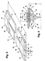
- FIG. 3 a shortened carrier element belonging to the wiper blade according to the invention in an enlarged, extended, perspective view
- FIG. 4 the sectional area of a section along the line IV-IV in FIG. 2 in an enlarged view
- FIG. 5 one in FIG. 2 with V designated detail in an enlarged view
- FIG. 6 the sectional area of a cut according to FIG. 4 by another embodiment of the wiper blade according to the invention
- FIG. 7 a FIG. 5 corresponding detail of the wiper blade according to FIG. 6,
- FIG. 8 the sectional area of a section according to the FIGS.
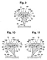
- FIG. 9 a schematic representation of the sectional area of a section along the line IX-IX in FIG. 2 by an inventive wiper blade in an enlarged view which is placed on the window surface to be wiped, FIG. 10 according to the wiper blade FIG. 9 during the wiping operation in the one wiping direction and FIG. 11 according to the wiper blade FIG. 9 during the wiping operation in the other wiping direction.
- wiper blade 10 has a strip-like elongated, resilient support member 12, on the underside 13 an elongated, rubber-elastic wiper strip 14 is arranged longitudinal axis parallel.
- the wiper blade-side part 16 of a connecting device is arranged in its middle section, with the aid of which the wiper blade 10 is articulated with an in FIG. 1 dash-dotted lines indicated, driven wiper arm 18 can be releasably connected.
- the wiper arm 18 is provided at its free end with the wiper arm side part of the connecting device.
- the wiper arm 18 is in the direction of the arrow 20 to be wiped disc - for example, the windshield of a motor vehicle - charged, the surface to be wiped in FIG. 1 is indicated by a dashed line 22. Since the line 22 is intended to represent the strongest curvature of the disk surface, it is clearly evident that the curvature of the wiper blade 10 which bears against the disk at its two ends is still greater than the maximum disk curvature (FIG. FIG. 1 ). Under the contact pressure (arrow 20), the wiper blade 10 applies its wiper lip 24 over its entire length to the disk surface 22 at. In this case, in the example made of metal, resilient support member 12, a voltage builds up, which for a proper Plant the wiper strip 14 and the wiper lip 24 over the entire length of the disc and ensures a uniform distribution of the contact pressure.
- FIG. 4 It can be seen that the support member 12 of the wiper blade 10 is located at a distance 26 in front of the disc to be wiped 22. In this case, its arrangement is such that its band surfaces 11 and 13 are located in a plane which extends substantially parallel to the wafer surface to be wiped 22.
- the particularly advantageous construction of the support element 12 is in particular from the FIGS. 3 and 4 seen. It has two band-like spring rails 28 and 30 lying in a common plane, which are aligned parallel to each other. The mutually facing inner longitudinal edges 32 are located at a distance 34 from each other.
- each bridge-like transverse web 36 and 38 is connected by a bridge-like transverse web 36 and 38 with each other; For example, welded together.
- each bridge-like transverse web lies with its end portions 40 on the upper side 11 of the support element 12 or on its spring rails 28, 30.
- Each of the two transverse webs 36 and 28 has a central portion 42 which is located at a distance 44 from the upper band surface 11 of the spring rails and thus establishes the bridge-like shape. Since the longitudinal extent 46 of the middle portions 42 is greater than the distance 34 between the facing inner longitudinal edges 32, the two spring rails 28 and 30 extend with inner edge strips 48 in the region of the central portions 42, wherein the edge strips 48 at a distance 44 below the middle portions 42 are arranged. In addition to the above-mentioned tasks of the support member 12 in terms of the contact force distribution this should also ensure a proper, stress-free management of the wiper strip 14 during wiping operation. This ensures a low-noise wiping operation.
- the wiper strip 14 of this first embodiment has a cross section based on the FIG. 4 should be made clear. It has a head strip 50, with which the actual wiping work taking over wiper lip 24 is connected via a narrow web bar 52. The arrangement of the web bar 52 allows a tilting of the wiper lip 24 in a wiping work-promoting towing position, which will be explained later.
- the head strip 50 is provided at its opposite longitudinal sides with longitudinal edges open to these longitudinal sides 54 and 56.
- the longitudinal grooves 54 and 56 serve to receive the inner edge strips 48 of the spring rails 28 and 30.
- the depth of the longitudinal grooves 54 and 56 is selected so that a wall 58 remains between the two longitudinal grooves.
- the head strip 50 thus has a base bar 60 and a cover strip 62, which are both connected to each other by the wall 58.
- the thickness 64 of the wall 58 is smaller than the distance 34 between the inner longitudinal edges 32 of the spring rails 28, 30 and smaller than the distance between the inner edge strips 48.
- the width of the two longitudinal grooves 54 and 56 in the head strip 50 is so on the thickness the spring rails 28, 30 or their inner edge strips 48 matched that a stress-free mounting of the wiper strip on the support member 12 is ensured when the wiper strip according to FIG. 4 with the support element 12 according to FIG. 3 assembled.
- the width 66 of the cover strip 62 is slightly smaller than the length of the bridge 46 to be designated as a bridge 46 of the central portion 42 and the thickness 67 is less than the distance 44 between the central portion 42 and the upper sides 11 of the spring rails 28, 30 can over their entire longitudinal extent a consistent cross-section having wiper strip 14 without difficulty in the longitudinal direction in the support member 12 is inserted and thus connected to this.
- FIG. 5 Another special feature of the wiper blade according to the invention is in FIG. 5 shown.
- the adjacent end face 72 arranged at one end of the support element transverse web 70 is provided on its side facing the wiper blade end in its central portion with an associated with him, the adjacent end face 72 at least partially overlapping stop 74.
- the stop 74 is formed by a bent, lobe-like extension of the central portion 42. If each of the two wiper blade ends or each of the two support element ends with a crosspiece 70 according to FIG. 5 is provided, it is important to ensure that the distance between the mutually facing inner walls 75 of the stop tabs 74 is slightly greater than the length 76 of the wiper strip 14 (FIG. FIG. 2 ).
- the length 78 of the support member 12 is slightly greater than the length 76 of the wiper strip 14.
- the two-sided arrangement of the stops 74 thus forms an effective safeguard against wandering out of the wiper strip 14 in the longitudinal direction of its support member 12 during the wiper operation.
- the bend of at least one of the two stop tabs 74 is made only after the insertion of the wiper strip 14 into the support element 12.
- the arranged in the central portion of the wiper blade 10 part 16 of the connecting device for the wiper arm engages around the respective outer, protruding from the longitudinal grooves 54 and 56 outer edge strips 80 of the spring rails 28, 30 and the support member 12.
- the connection between the part 16 and the support member 12 can be positive and / or non-positive. With a corresponding length of the wiper blade, it may also be expedient if further corresponding transverse webs are arranged between the two transverse webs 36 and 38 arranged at the end.
- a preferably made of plastic covering cap 82 is preferably snapped on the two spring rails 28, 30 and the end-side transverse webs 36, 38 Figures 1 and 2 ).
- FIGS. 6 to 8 Further embodiments of the wiper blade according to the invention are in the FIGS. 6 to 8 shown.
- the support elements of these embodiments correspond completely to the already described support elements 12 from the FIGS. 3 to 5 , so that the reference numerals used in these figures can be adopted directly.
- the configuration of the wiper strip 100 in this embodiment differs in principle from the structure of the wiper strip 14 in the embodiment already described.
- FIG. 6 shows, the wiper strip 100 has only one wiper lip 101, which is integrally connected via a web bar 102 with a cover strip 104.
- the already described embodiment according to the FIGS. 4 and 5 existing base strip 60 is thus eliminated.
- the inner edge strips 48 of the spring rails 28 and 30 are in groove-like constrictions 106 of the wiper strip 100, which are necessary to form the narrow web bar 102.
- each of the two inner longitudinal edges 32 of the two spring rails 28, 30 and the support member 12 is disposed in one of the two groove-like constrictions 106 of the wiper strip 100.
- the two lateral boundary surfaces 110 of the constrictions 106 are of spherical design and are arranged so that the width dimension of the groove-like constrictions 106 is wider at least over an outer portion
- the width 112 of the web bar 102 is so matched to the distance 34 between the facing inner longitudinal edges 32 of the spring rails 28, 30, that an air gap remains between the web bar and the spring rails.
- the thickness 114 of the cover strip 104 is slightly smaller than the distance 44 between the central portion 42 of the transverse web 36 and the inner edge strip 48.
- the width 116 of the cover strip 104 is slightly less than the longitudinal extent 46 of the central portion 42 of the bridge-like transverse webs 36th This makes it possible to introduce the wiper strip 100, which has a constant cross-section over its entire length, without obstacles in its longitudinal extent into the support element 112, so that the in FIG. 6 shown mounting position is obtained. Also in this embodiment, the plane in which the support member 12 extends at a distance 26 from the surface 22 of the disc to be wiped 22nd
- each of the two bridge-like transverse webs 70 may be provided at its seen in the longitudinal extent of the wiper blade outer ends with a bent stop 74, so that after insertion of the wiper strip 14 in the support member 12 and the Abkröpfen the stopper flaps 74 a reliable longitudinal securing of the wiper strip 100 in the support member 12 is ensured. It is clear that even in this embodiment, the distance between the mutually facing inner walls 75 of the stop tabs 74 must be slightly larger than the length 76 of the wiper strip.
- FIG. 8 A further embodiment of the wiper blade according to the invention is intended to be based on FIG. 8 be explained.
- the embodiment according to FIG. 8 corresponds in its basic structure to the structure of the basis of FIG. 6 described embodiment. Notwithstanding the embodiment according to FIG. 6 However, in this embodiment, not only the lateral boundary surfaces 110 but also the other, formed on the cover strip 104 lateral boundary surfaces 108 of the groove-like constrictions 106 are formed crowned. Further, the embodiment differs according to FIG. 8 from the embodiment according to FIG. 6 nor by a arranged in the wiper lip 101, continuous completely closed Longitudinal channel 118.
- the arrangement of the longitudinal channel 118 in the wiper lip can provide on its own or in conjunction with other longitudinal grooves for a soft, low-noise Umlege the wiper lip during wiping operation. Also, its arrangement is not necessarily in connection with the crowned formation of the boundary surfaces 108, 110 required.
- the width of the support element 12 over the entire longitudinal extent is the same.
- the support element tapers towards the end portions of the wiper blade. So that the part 16 can be fastened to the wiper blade, it is sufficient if each spring rail 28, 30 protrudes from its groove-like constriction at least with a middle, outer edge strip 80, so that the part 16 of the connection device can be fastened to this edge strip 80.
- the two spring rails may be formed as separate components and arranged in the groove-like constrictions of the wiper strip. Ensuring in particular the distance dimension 34 can then be taken over by further, not shown components.
- FIGS. 9 to 11 show principle sectional views of the wiper blade according to the FIGS. 6 and 7 , cut along the line IX-IX in FIG FIG. 2 being in FIG. 9 the wiper blade 10 is placed with its wiper lip 101 only on the wafer surface to be wiped 22.
- the wiper strip 100 is held with play between the inner longitudinal edges 32 of the two spring rails 28, 30 (see also FIGS. 3 and 4 ). Since the length 76 of the wiper strip 100 is also slightly smaller than the length 78 of the support element 12 or less than the dimension between the mutually facing inner walls 75 of the stops 74 at the two ends of the support member 12 results in a so-called "free-floating", stress-free but reliable support of the wiper strip 100 in the support member 12th
- the wiper blade 10 under load by the contact pressure (arrow 20 in Fig. 1 ) in the direction of arrow 122 in FIG Fig. 10 is moved over the disc 22, tilts the wiper lip 101 in the region of the web bar 102 in an advantageous towing position with the support member 12 of the disc somewhat approaches (arrow 123).
- the tilting movement is limited by the fact that the one, lateral boundary surface 110 of a groove-like constriction 106 on the underside 13 of a spring rail 30 is supported.
- the wiper lip 101 tilts over one FIG. 9 apparent intermediate position into its other towing position ( Fig. 11 ) wherein the wiper lip 101 is supported with the lateral boundary surface 110 of the other groove-like constriction 106 on the underside 13 of the other spring rail 28.
Landscapes
- Engineering & Computer Science (AREA)
- Mechanical Engineering (AREA)
- Ink Jet (AREA)
- Cleaning In General (AREA)
- Vehicle Cleaning, Maintenance, Repair, Refitting, And Outriggers (AREA)
- Window Of Vehicle (AREA)
- Body Structure For Vehicles (AREA)
- Springs (AREA)
Claims (19)
- Balai d'essuie-glace (10) pour vitres, de préférence de véhicules automobiles, comprenant une raclette de balai d'essuie-glace (14) allongée, ayant l'élasticité du caoutchouc, pouvant être appliquée contre la vitre (22), qui est disposée parallèlement à l'axe longitudinal sur un élément de support (12) allongé, élastique à ressort, auquel est directement connecté un dispositif de raccordement du balai d'essuie-glace à un bras d'essuie-glace entraîné (18), l'élément de support (12) ayant deux rails élastiques (28, 30) en forme de bande disposés dans un plan situé devant la vitre, essentiellement parallèle à la vitre, dont les surfaces de bande inférieures (13) sont tournées vers la vitre, dont les arêtes longitudinales intérieures (48) adjacentes l'une à l'autre, à distance (34) l'une de l'autre, plongent dans une rainure longitudinale respective (54, 56, 106) ouverte vers le côté longitudinal de la raclette de balai d'essuie-glace (14) et associée à chaque arête longitudinale, les deux rails élastiques (28, 30) étant connectés l'un à l'autre par au moins deux nervures transversales (36, 38) en forme de pont, du côté de l'extrémité dans la direction longitudinale, caractérisé en ce que sur les deux rails élastiques (28) est disposé un chapeau de recouvrement (82) qui est encliqueté sur les nervures transversales (36, 38).
- Balai d'essuie-glace selon la revendication 1, caractérisé en ce que le capuchon de recouvrement (82) est disposé sur les côtés d'extrémité de l'élément de support (12).
- Balai d'essuie-glace selon la revendication 1 ou 2, caractérisé en ce que le capuchon de recouvrement (82) est fabriqué en plastique.
- Balai d'essuie-glace selon l'une quelconque des revendications précédentes, caractérisé en ce que chaque nervure transversale (36, 38) a une portion centrale (42) qui s'étend à distance (44) des surfaces de bande supérieures (11) des rails élastiques (28, 30), de sorte que des nervures transversales en forme de pont (36, 38) en résultent, la distance (34) entre les deux rails longitudinaux (28, 30) étant inférieure à la largeur du pont (46).
- Balai d'essuie-glace selon l'une quelconque des revendications précédentes, caractérisé en ce que les nervures transversales (36, 38) sont réalisées sous forme de composants séparés et sont connectées fixement aux deux rails élastiques (28, 30).
- Balai d'essuie-glace selon l'une quelconque des revendications précédentes, caractérisé en ce que les nervures transversales (36, 38) sont fixées sur les surfaces de bande supérieures (11) des deux rails élastiques (28, 30).
- Balai d'essuie-glace selon l'une quelconque des revendications précédentes, caractérisé en ce que les nervures transversales (36, 38) sont soudées aux deux rails élastiques (28, 30).
- Balai d'essuie-glace selon l'une quelconque des revendications précédentes, caractérisé en ce que la longueur (78) des rails élastiques est supérieure à la longueur (76) de la raclette de balai d'essuie-glace (14).
- Balai d'essuie-glace selon l'une quelconque des revendications précédentes, caractérisé en ce qu'au moins sur chaque portion d'extrémité des deux rails élastiques (28, 30) associés l'un à l'autre est disposée une nervure transversale (36, 38).
- Balai d'essuie-glace selon l'une quelconque des revendications précédentes, caractérisé en ce qu'une nervure transversale disposée dans la région centrale des deux rails élastiques (28, 30) associés l'un à l'autre est réalisée en tant que pièce (16) d'un dispositif de raccordement pour connecter le balai d'essuie-glace (10) au bras d'essuie-glace (18).
- Balai d'essuie-glace selon l'une quelconque des revendications précédentes, caractérisé en ce qu'au moins l'une des deux nervures transversales (36, 38) disposées sur une portion d'extrémité des rails élastiques (28, 30) est pourvue d'une butée (74) connectée à sa portion centrale (42), recouvrant en partie le côté frontal (72) de la raclette de balai d'essuie-glace qui lui est adjacent.
- Balai d'essuie-glace selon l'une quelconque des revendications précédentes, caractérisé en ce que les deux nervures transversales (36, 38) disposées aux extrémités de l'élément de support (12) sont pourvues d'une butée (74).
- Balai d'essuie-glace selon l'une quelconque des revendications précédentes, caractérisé en ce que l'épaisseur (64) d'une paroi (58) prévue entre les deux rainures longitudinales (54, 56) dans la raclette de balai d'essuie-glace (14) est inférieure à la distance (34) entre les arêtes longitudinales (32) adjacentes l'une à l'autre des deux rails élastiques (28, 30) associés l'un à l'autre.
- Balai d'essuie-glace selon l'une quelconque des revendications précédentes, caractérisé en ce que la raclette de balai d'essuie-glace (100) présentant sur son étendue longitudinale une section transversale uniforme a une lèvre de balai d'essuie-glace (101) en forme de raclette pouvant s'appliquer contre la vitre, qui est connectée, par le biais d'une nervure d'âme étroite (102) formée par des rétrécissements en forme de rainure (106) opposés l'un à l'autre, à une baguette de recouvrement (104) maintenue sur l'élément de support (12) et en ce que chacune des deux arêtes longitudinales intérieures (32), adjacentes l'une à l'autre, des rails élastiques (28, 30), est disposée dans l'un des deux rétrécissements (106) en forme de rainure de la raclette de balai d'essuie-glace (100).
- Balai d'essuie-glace selon la revendication 14, caractérisé en ce que les surfaces de limitation latérales (108, 110) des rétrécissements en forme de rainure (106) divergent depuis la nervure d'âme (102) vers les côtés longitudinaux de la raclette de balai d'essuie-glace.
- Balai d'essuie-glace selon la revendication 15, caractérisé en ce que l'une des surfaces de limitation latérales (110) des rétrécissements en forme de rainure (106) a une allure bombée, vue en section transversale.
- Balai d'essuie-glace selon la revendication 15, caractérisé en ce que les deux surfaces de limitation latérales (108, 110) des rétrécissements en forme de rainure (106) ont une allure bombée, vue en section transversale.
- Balai d'essuie-glace selon l'une quelconque des revendications 1 à 17, caractérisé en ce que la lèvre de balai d'essuie-glace (101) présente un canal longitudinal (118) fermé de tous les côtés.
- Balai d'essuie-glace selon l'une quelconque des revendications 1 à 18, caractérisé en ce que chaque rail élastique (28, 30) fait saillie au moins avec une bande de bord centrale hors de son rétrécissement en forme de rainure (106).
Applications Claiming Priority (3)
| Application Number | Priority Date | Filing Date | Title |
|---|---|---|---|
| DE10025706 | 2000-05-25 | ||
| DE10025706A DE10025706A1 (de) | 2000-05-25 | 2000-05-25 | Wischblatt zum Reinigen von Fahrzeugscheiben |
| EP01940118A EP1289805B1 (fr) | 2000-05-25 | 2001-04-04 | Raclette d'essuie-glace pour le nettoyage de vitres de vehicules |
Related Parent Applications (2)
| Application Number | Title | Priority Date | Filing Date |
|---|---|---|---|
| EP01940118.1 Division | 2001-04-04 | ||
| EP01940118A Division EP1289805B1 (fr) | 2000-05-25 | 2001-04-04 | Raclette d'essuie-glace pour le nettoyage de vitres de vehicules |
Publications (2)
| Publication Number | Publication Date |
|---|---|
| EP1547883A1 EP1547883A1 (fr) | 2005-06-29 |
| EP1547883B1 true EP1547883B1 (fr) | 2012-02-22 |
Family
ID=7643388
Family Applications (2)
| Application Number | Title | Priority Date | Filing Date |
|---|---|---|---|
| EP01940118A Expired - Lifetime EP1289805B1 (fr) | 2000-05-25 | 2001-04-04 | Raclette d'essuie-glace pour le nettoyage de vitres de vehicules |
| EP05102152A Expired - Lifetime EP1547883B1 (fr) | 2000-05-25 | 2001-04-04 | Balai d'essuie-glace pour nettoyer des pare-brise de vehicules |
Family Applications Before (1)
| Application Number | Title | Priority Date | Filing Date |
|---|---|---|---|
| EP01940118A Expired - Lifetime EP1289805B1 (fr) | 2000-05-25 | 2001-04-04 | Raclette d'essuie-glace pour le nettoyage de vitres de vehicules |
Country Status (12)
| Country | Link |
|---|---|
| US (1) | US6978512B2 (fr) |
| EP (2) | EP1289805B1 (fr) |
| JP (1) | JP4856348B2 (fr) |
| KR (1) | KR100764952B1 (fr) |
| CN (1) | CN1196612C (fr) |
| AU (1) | AU780818B2 (fr) |
| BR (1) | BR0106665B1 (fr) |
| CZ (2) | CZ299497B6 (fr) |
| DE (3) | DE10025706A1 (fr) |
| ES (2) | ES2243507T3 (fr) |
| RU (1) | RU2272724C2 (fr) |
| WO (1) | WO2001089891A1 (fr) |
Cited By (5)
| Publication number | Priority date | Publication date | Assignee | Title |
|---|---|---|---|---|
| US8806700B2 (en) | 2011-07-29 | 2014-08-19 | Pylon Manufacturing Corporation | Wiper blade connector |
| US9108595B2 (en) | 2011-07-29 | 2015-08-18 | Pylon Manufacturing Corporation | Windshield wiper connector |
| US9457768B2 (en) | 2011-04-21 | 2016-10-04 | Pylon Manufacturing Corp. | Vortex damping wiper blade |
| US9505380B2 (en) | 2014-03-07 | 2016-11-29 | Pylon Manufacturing Corp. | Windshield wiper connector and assembly |
| USD777079S1 (en) | 2014-10-03 | 2017-01-24 | Pylon Manufacturing Corp. | Wiper blade frame |
Families Citing this family (43)
| Publication number | Priority date | Publication date | Assignee | Title |
|---|---|---|---|---|
| DE10025710A1 (de) * | 2000-02-23 | 2001-08-30 | Bosch Gmbh Robert | Wischblatt für Scheiben insbesondere von Kraftfahrzeugen |
| DE10033778A1 (de) | 2000-07-12 | 2002-04-18 | Valeo Auto Electric Gmbh | Wischvorrichtung |
| US6966096B2 (en) * | 2000-10-28 | 2005-11-22 | Robert Bosch Gmbh | Device for connecting a wiper arm to a wiper blade and wiper arm and wiper blade using such a device |
| DE10120467A1 (de) | 2001-04-26 | 2002-10-31 | Bosch Gmbh Robert | Wischblatt zum Reinigen von Scheiben, insbesondere von Kraftfahrzeugen |
| DE10259478A1 (de) | 2002-12-19 | 2004-07-01 | Robert Bosch Gmbh | Wischvorrichtung für Scheiben von Kraftfahrzeugen |
| DE10341275A1 (de) * | 2003-09-08 | 2005-03-31 | Robert Bosch Gmbh | Wischblatt |
| DE602004007097T3 (de) * | 2004-02-26 | 2014-01-16 | Federal-Mogul S.A. | Scheibenwischervorrichtung |
| DE102004015423A1 (de) * | 2004-03-26 | 2005-10-13 | Robert Bosch Gmbh | Wischblatt |
| ES2303182T3 (es) * | 2005-01-25 | 2008-08-01 | Federal-Mogul S.A. | Dispositivo limpiaparabrisas. |
| TWM279554U (en) * | 2005-06-20 | 2005-11-01 | Ji-Sheng Jang | Improvement of windshield wiper structure |
| ES2328167T3 (es) * | 2006-05-08 | 2009-11-10 | Federal-Mogul S.A. | Un dispositivo de limpiparabrisas. |
| US8122560B2 (en) * | 2006-08-04 | 2012-02-28 | Dongguan Hongyi Wiper Co., Ltd. | Windshield wiper bridge base assembly |
| US20080028564A1 (en) * | 2006-08-04 | 2008-02-07 | Shu-Lan Ku | Wiper blade support structure |
| DE102006050815A1 (de) * | 2006-10-27 | 2008-04-30 | Robert Bosch Gmbh | Wischblatt |
| US7992248B2 (en) * | 2007-05-22 | 2011-08-09 | Federal-Mogul Corporation | Spoilerless flat wiper blade assembly |
| EP2008890B1 (fr) * | 2007-06-26 | 2012-10-03 | Federal-Mogul S.A. | Dispositif d'essuie-glace |
| KR101098004B1 (ko) | 2009-08-26 | 2011-12-22 | 주식회사 캐프 | 차량 와이퍼용 멀티 어댑터 |
| US8552690B2 (en) * | 2009-11-06 | 2013-10-08 | Rally Manufacturing, Inc. | Method and system for automatically detecting a voltage of a battery |
| US20130227809A1 (en) | 2012-02-24 | 2013-09-05 | Pylon Manufacturing Corp. | Wiper blade |
| DE102010028102A1 (de) * | 2010-04-22 | 2011-10-27 | Robert Bosch Gmbh | Wischblatt für einen Scheibenwischer |
| US8495787B2 (en) | 2010-08-03 | 2013-07-30 | Rally Manufacturing, Inc. | Windshield wiper |
| USD706200S1 (en) | 2010-09-22 | 2014-06-03 | Pylon Manufacturing Corporation | Windshield wiper cover |
| US8575895B2 (en) | 2011-03-29 | 2013-11-05 | Rally Manufacturing, Inc. | Method and device for voltage detection and charging of electric battery |
| US9174609B2 (en) | 2011-04-21 | 2015-11-03 | Pylon Manufacturing Corp. | Wiper blade with cover |
| MX345011B (es) | 2011-07-28 | 2017-01-11 | Pylon Mfg Corp | Adaptador, conector y conjunto de limpiaparabrisas. |
| MX347284B (es) | 2011-07-29 | 2017-04-21 | Pylon Mfg Corp | Conector de limpiaparabrisas. |
| US8997304B2 (en) | 2011-12-14 | 2015-04-07 | Federal-Mogul Corporation | Windscreen wiper device |
| US20130219649A1 (en) | 2012-02-24 | 2013-08-29 | Pylon Manufacturing Corp. | Wiper blade |
| US10829092B2 (en) | 2012-09-24 | 2020-11-10 | Pylon Manufacturing Corp. | Wiper blade with modular mounting base |
| US10166951B2 (en) | 2013-03-15 | 2019-01-01 | Pylon Manufacturing Corp. | Windshield wiper connector |
| KR101474838B1 (ko) | 2013-07-01 | 2014-12-22 | 주식회사 캐프 | 와이퍼 블레이드 조립체 |
| CN103879382A (zh) * | 2014-02-25 | 2014-06-25 | 厦门福来德汽配有限公司 | 雨刷 |
| KR101565825B1 (ko) * | 2014-03-11 | 2015-11-05 | 케이씨더블류 주식회사 | 플랫 와이퍼 블레이드 및 그 결합방법 |
| FR3023810B1 (fr) * | 2014-07-17 | 2018-01-19 | Valeo Systemes D'essuyage | Balai plat carene d'essuie-glace |
| USD787308S1 (en) | 2014-10-03 | 2017-05-23 | Pylon Manufacturing Corp. | Wiper blade package |
| WO2017075066A1 (fr) | 2015-10-26 | 2017-05-04 | Pylon Manufacturing Corp. | Balai d'essuie-glace |
| CN109311452A (zh) | 2016-05-19 | 2019-02-05 | 电缆塔制造有限公司 | 挡风玻璃雨刮器连接器 |
| AU2017268008A1 (en) | 2016-05-19 | 2018-11-22 | Pylon Manufacturing Corp. | Windshield wiper connector |
| WO2017201485A1 (fr) | 2016-05-19 | 2017-11-23 | Pylon Manufacturing Corp. | Connecteur d'essuie-glace |
| US11040705B2 (en) | 2016-05-19 | 2021-06-22 | Pylon Manufacturing Corp. | Windshield wiper connector |
| WO2017201473A1 (fr) | 2016-05-19 | 2017-11-23 | Pylon Manufacturing Corp. | Balai d'essuie-glace |
| WO2018081791A1 (fr) | 2016-10-31 | 2018-05-03 | Pylon Manufacturing Corp. | Balai d'essuie-glace pourvu d'une coiffe |
| CN109795452B (zh) * | 2019-03-25 | 2020-08-11 | 厦门富可汽车配件有限公司 | 一种雨刷胶条防脱结构及其雨刷 |
Family Cites Families (22)
| Publication number | Priority date | Publication date | Assignee | Title |
|---|---|---|---|---|
| US2687544A (en) * | 1950-05-10 | 1954-08-31 | Trico Products Corp | Windshield cleaner |
| DE1028896B (de) * | 1954-06-24 | 1958-04-24 | Avog Elektro Und Feinmechanik | Wischerschiene fuer Scheibenwischer |
| US2983945A (en) * | 1958-03-12 | 1961-05-16 | Anderson Co | Wiper blade assembly |
| US3084372A (en) * | 1959-10-14 | 1963-04-09 | Anderson Co | Windshield wiper assembly |
| US3116507A (en) * | 1960-05-02 | 1964-01-07 | Trico Products Corp | Windshield wiper system |
| DE1505357A1 (de) | 1965-01-23 | 1969-05-29 | Otto Bloetz | Fahrzeug zur Befoerderung von pulverigem Schuettgut |
| US3430285A (en) * | 1968-01-31 | 1969-03-04 | Daco Inc | Holder for windshield wiper blade |
| GB1269993A (en) * | 1969-05-17 | 1972-04-12 | Kenneth Jenkinson Meadows | Improvements in or relating to windscreen wiper blades |
| US3636583A (en) * | 1970-01-26 | 1972-01-25 | Ian K Rosen | Squeegee blade |
| US3626544A (en) * | 1970-09-16 | 1971-12-14 | Roberk Co The | Clip for windshield wiper blade refill |
| US3958295A (en) * | 1972-10-03 | 1976-05-25 | Tridon Limited | Backing members for use in windshield wipers |
| CH624349A5 (fr) * | 1978-12-05 | 1981-07-31 | J B Brevets | |
| DE9201307U1 (de) | 1992-02-04 | 1993-05-27 | Robert Bosch Gmbh, 7000 Stuttgart | Wischblatt zum Überstreichen von Scheiben an Kraftfahrzeugen |
| DE19627115A1 (de) * | 1996-07-05 | 1998-01-08 | Bosch Gmbh Robert | Wischblatt für Scheiben von Kraftfahrzeugen |
| DE29611722U1 (de) | 1996-07-05 | 1997-11-06 | Robert Bosch Gmbh, 70469 Stuttgart | Wischblatt für Scheiben von Kraftfahrzeugen |
| DE19627114A1 (de) * | 1996-07-05 | 1998-01-08 | Bosch Gmbh Robert | Wischblatt für Scheiben von Kraftfahrzeugen |
| DE19650159A1 (de) * | 1996-12-04 | 1998-06-10 | Teves Gmbh Alfred | Wischblatt zur Reinigen von Scheiben an Fahrzeugen |
| DE19718490A1 (de) * | 1997-05-02 | 1998-11-05 | Bosch Gmbh Robert | Wischblatt für Scheiben von Kraftfahrzeugen |
| DE19729864A1 (de) | 1997-07-11 | 1999-01-14 | Bosch Gmbh Robert | Wischblatt zum Reinigen von Fahrzeugscheiben |
| DE19801058A1 (de) * | 1998-01-14 | 1999-07-15 | Bosch Gmbh Robert | Wischblatt zum Reinigen von Scheiben von Kraftfahrzeugen |
| DE19802451A1 (de) * | 1998-01-23 | 1999-07-29 | Bosch Gmbh Robert | Wischblatt für Scheiben von Kraftfahrzeugen mit einem langgestreckten, federelastischen Tragelement |
| AUPP298898A0 (en) | 1998-04-16 | 1998-05-07 | Trico Products Corporation | Wiper refill retainer clip |
-
2000
- 2000-05-25 DE DE10025706A patent/DE10025706A1/de not_active Withdrawn
-
2001
- 2001-04-04 ES ES01940118T patent/ES2243507T3/es not_active Expired - Lifetime
- 2001-04-04 CZ CZ20070872A patent/CZ299497B6/cs not_active IP Right Cessation
- 2001-04-04 AU AU73825/01A patent/AU780818B2/en not_active Expired
- 2001-04-04 JP JP2001586098A patent/JP4856348B2/ja not_active Expired - Lifetime
- 2001-04-04 ES ES05102152T patent/ES2379633T3/es not_active Expired - Lifetime
- 2001-04-04 CZ CZ20020198A patent/CZ299276B6/cs not_active IP Right Cessation
- 2001-04-04 DE DE50106797T patent/DE50106797D1/de not_active Expired - Lifetime
- 2001-04-04 CN CNB018014011A patent/CN1196612C/zh not_active Expired - Lifetime
- 2001-04-04 WO PCT/DE2001/001303 patent/WO2001089891A1/fr active IP Right Grant
- 2001-04-04 EP EP01940118A patent/EP1289805B1/fr not_active Expired - Lifetime
- 2001-04-04 RU RU2002103314/11A patent/RU2272724C2/ru active
- 2001-04-04 EP EP05102152A patent/EP1547883B1/fr not_active Expired - Lifetime
- 2001-04-04 US US10/031,828 patent/US6978512B2/en not_active Expired - Lifetime
- 2001-04-04 KR KR1020027001004A patent/KR100764952B1/ko active IP Right Grant
- 2001-04-04 BR BRPI0106665-0A patent/BR0106665B1/pt not_active IP Right Cessation
- 2001-04-04 DE DE10192046.6T patent/DE10192046B4/de not_active Expired - Lifetime
Cited By (5)
| Publication number | Priority date | Publication date | Assignee | Title |
|---|---|---|---|---|
| US9457768B2 (en) | 2011-04-21 | 2016-10-04 | Pylon Manufacturing Corp. | Vortex damping wiper blade |
| US8806700B2 (en) | 2011-07-29 | 2014-08-19 | Pylon Manufacturing Corporation | Wiper blade connector |
| US9108595B2 (en) | 2011-07-29 | 2015-08-18 | Pylon Manufacturing Corporation | Windshield wiper connector |
| US9505380B2 (en) | 2014-03-07 | 2016-11-29 | Pylon Manufacturing Corp. | Windshield wiper connector and assembly |
| USD777079S1 (en) | 2014-10-03 | 2017-01-24 | Pylon Manufacturing Corp. | Wiper blade frame |
Also Published As
| Publication number | Publication date |
|---|---|
| CN1196612C (zh) | 2005-04-13 |
| DE10192046B4 (de) | 2019-01-10 |
| CZ299276B6 (cs) | 2008-06-04 |
| AU7382501A (en) | 2001-12-03 |
| EP1289805A1 (fr) | 2003-03-12 |
| ES2243507T3 (es) | 2005-12-01 |
| DE50106797D1 (de) | 2005-08-25 |
| BR0106665B1 (pt) | 2009-08-11 |
| ES2379633T3 (es) | 2012-04-30 |
| JP2003534193A (ja) | 2003-11-18 |
| CZ299497B6 (cs) | 2008-08-13 |
| CN1380863A (zh) | 2002-11-20 |
| US6978512B2 (en) | 2005-12-27 |
| WO2001089891A1 (fr) | 2001-11-29 |
| US20020148064A1 (en) | 2002-10-17 |
| RU2272724C2 (ru) | 2006-03-27 |
| AU780818B2 (en) | 2005-04-21 |
| DE10192046D2 (de) | 2002-10-10 |
| CZ2002198A3 (cs) | 2002-06-12 |
| JP4856348B2 (ja) | 2012-01-18 |
| DE10025706A1 (de) | 2001-11-29 |
| KR100764952B1 (ko) | 2007-10-08 |
| BR0106665A (pt) | 2002-04-02 |
| EP1547883A1 (fr) | 2005-06-29 |
| KR20020029432A (ko) | 2002-04-18 |
| EP1289805B1 (fr) | 2005-07-20 |
Similar Documents
| Publication | Publication Date | Title |
|---|---|---|
| EP1547883B1 (fr) | Balai d'essuie-glace pour nettoyer des pare-brise de vehicules | |
| EP1695881B1 (fr) | Balai d'essuie-glace pour essuyer les vitres de véhicules | |
| EP1347896B1 (fr) | Dispositif d'essuie-glace, en particulier pour vitres de vehicules automobiles | |
| DE10291817B4 (de) | Wischblatt zum Reinigen von Scheiben, insbesondere von Kraftfahrzeugen | |
| EP1098795B1 (fr) | Essuie-glace pour vitres de vehicules automobiles | |
| DE19833666B4 (de) | Wischblatt für Scheiben von Kraftfahrzeugen | |
| EP1053143B1 (fr) | Dispositif pour l'assemblage articule d'une raclette d'essuie-glace pour vitres de vehicules automobiles avec un bras d'essuie-glace | |
| EP1278666B1 (fr) | Balai d'essuie-glace pour des vitres, en particulier de vehicules a moteur | |
| EP1071590B1 (fr) | Dispositif de liaison articulee entre une raclette d'essuie-glace de vehicule a moteur et un bras d'essuie-glace | |
| WO2001062561A1 (fr) | Balai d'essuie-glace pour nettoyer les vitres d'automobiles | |
| DE29918961U1 (de) | Wischvorrichtung für Scheiben von Kraftfahrzeugen | |
| EP1117576A1 (fr) | Dispositif d'essuie-glace pour vitres d'automobiles comportant un bras d'essuie-glace sollicite en direction de la vitre et depla able entre des positions reversibles | |
| WO2001051323A1 (fr) | Raclette d'essuie-glace pour vehicules, en particulier des vehicules automobiles | |
| DE19901818B4 (de) | Wischerblatt | |
| DE10000375A1 (de) | Wischblatt | |
| DE10007800A1 (de) | Wischblatt | |
| DE10350274B4 (de) | Wischblatt zum Reinigen von Scheiben insbesondere von Kraftfahrzeugen | |
| DE102011089545A1 (de) | Anschlusselement zum gelenkigen Verbinden eines Wischarms mit einem Wischblatt | |
| DE20221548U1 (de) | Wischblatt zum Reinigen von Scheiben insbesondere von Kraftfahrzeugen | |
| DE20314551U1 (de) | Wischhebel mit einem einendig angetriebenen Wischerarm, an dessen freien Ende ein an einer Scheibe anlegbares Wischblatt angeordnet ist | |
| DE20221526U1 (de) | Wischblatt zum Reinigen von Scheiben insbesondere von Kraftfahrzeugen |
Legal Events
| Date | Code | Title | Description |
|---|---|---|---|
| PUAI | Public reference made under article 153(3) epc to a published international application that has entered the european phase |
Free format text: ORIGINAL CODE: 0009012 |
|
| AC | Divisional application: reference to earlier application |
Ref document number: 1289805 Country of ref document: EP Kind code of ref document: P |
|
| AK | Designated contracting states |
Kind code of ref document: A1 Designated state(s): DE ES FR GB IT |
|
| 17P | Request for examination filed |
Effective date: 20051229 |
|
| AKX | Designation fees paid |
Designated state(s): DE ES FR GB IT |
|
| GRAP | Despatch of communication of intention to grant a patent |
Free format text: ORIGINAL CODE: EPIDOSNIGR1 |
|
| GRAS | Grant fee paid |
Free format text: ORIGINAL CODE: EPIDOSNIGR3 |
|
| GRAA | (expected) grant |
Free format text: ORIGINAL CODE: 0009210 |
|
| AC | Divisional application: reference to earlier application |
Ref document number: 1289805 Country of ref document: EP Kind code of ref document: P |
|
| AK | Designated contracting states |
Kind code of ref document: B1 Designated state(s): DE ES FR GB IT |
|
| REG | Reference to a national code |
Ref country code: GB Ref legal event code: FG4D Free format text: NOT ENGLISH |
|
| REG | Reference to a national code |
Ref country code: DE Ref legal event code: R096 Ref document number: 50116063 Country of ref document: DE Effective date: 20120419 |
|
| REG | Reference to a national code |
Ref country code: ES Ref legal event code: FG2A Ref document number: 2379633 Country of ref document: ES Kind code of ref document: T3 Effective date: 20120430 |
|
| PLBE | No opposition filed within time limit |
Free format text: ORIGINAL CODE: 0009261 |
|
| STAA | Information on the status of an ep patent application or granted ep patent |
Free format text: STATUS: NO OPPOSITION FILED WITHIN TIME LIMIT |
|
| 26N | No opposition filed |
Effective date: 20121123 |
|
| REG | Reference to a national code |
Ref country code: DE Ref legal event code: R097 Ref document number: 50116063 Country of ref document: DE Effective date: 20121123 |
|
| REG | Reference to a national code |
Ref country code: FR Ref legal event code: PLFP Year of fee payment: 16 |
|
| REG | Reference to a national code |
Ref country code: FR Ref legal event code: PLFP Year of fee payment: 17 |
|
| REG | Reference to a national code |
Ref country code: FR Ref legal event code: PLFP Year of fee payment: 18 |
|
| PGFP | Annual fee paid to national office [announced via postgrant information from national office to epo] |
Ref country code: FR Payment date: 20200421 Year of fee payment: 20 Ref country code: ES Payment date: 20200516 Year of fee payment: 20 Ref country code: DE Payment date: 20200623 Year of fee payment: 20 |
|
| PGFP | Annual fee paid to national office [announced via postgrant information from national office to epo] |
Ref country code: GB Payment date: 20200423 Year of fee payment: 20 Ref country code: IT Payment date: 20200423 Year of fee payment: 20 |
|
| REG | Reference to a national code |
Ref country code: DE Ref legal event code: R071 Ref document number: 50116063 Country of ref document: DE |
|
| REG | Reference to a national code |
Ref country code: GB Ref legal event code: PE20 Expiry date: 20210403 |
|
| REG | Reference to a national code |
Ref country code: ES Ref legal event code: FD2A Effective date: 20210726 |
|
| PG25 | Lapsed in a contracting state [announced via postgrant information from national office to epo] |
Ref country code: GB Free format text: LAPSE BECAUSE OF EXPIRATION OF PROTECTION Effective date: 20210403 |
|
| PG25 | Lapsed in a contracting state [announced via postgrant information from national office to epo] |
Ref country code: ES Free format text: LAPSE BECAUSE OF EXPIRATION OF PROTECTION Effective date: 20210405 |